Cutting
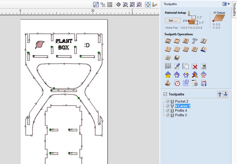
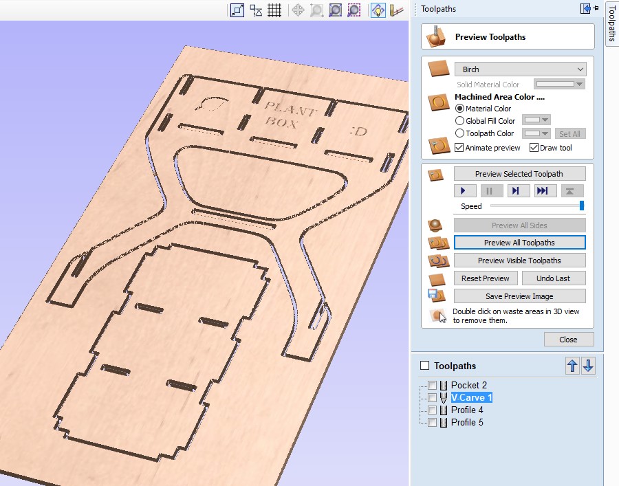
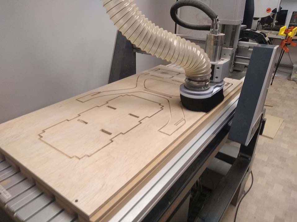
Once I was satisfied with the toolpaths for all 3 sheets, I put them on a USB and transferred them over to the CNC milling machine. Our lab has a 24 x 48 AXIOM mill, which is what I used to cut all of the parts for this project. This job involved 2 tool changes, and 5 z-leveling operations. It is important to zero the Z-axis after changing the bit, or swapping in for a new material.
Changing the bit involves two wrenches. One to hold the collet, and one to hold the fixture it is attached to. When unscrewing the collet, you want the bottom wrench to be to the right of the top wrench, so that you can pull the two wrenches together with one hand. This is an easy way to loosen it without pinching any part of your hand between the wrenches when they suddenly move. Once it has been loosened enough to slide the bit out, you can then put the new bit in. Make sure to slide the bit in far enough that the collet can grip it well, and the bit won’t be under too much stress. Tighten it thoroughly so that the bit won’t slide out.
Next you need to zero the z-axis to the material you are cutting. This process can vary slightly depending on the machine, but with my machine it is done by plugging in a metal puck into the gantry, and hitting a “tool set” button to have it lower down until the bit touches the puck and completes a circuit.

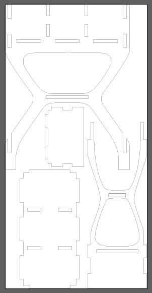

![[SVG download 1]](../design/PlantBoxSheet1.svg)
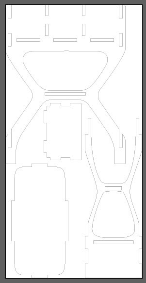
![[SVG download 2]](../design/PlantBoxSheet2.svg)
![[SVG download 3]](../design/PlantBoxSheet3.svg)