Week 5: 3D printing and scanning
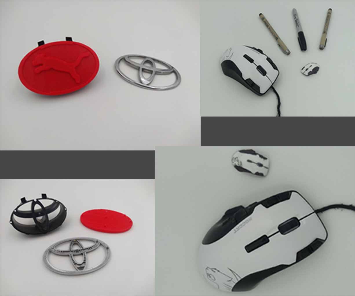
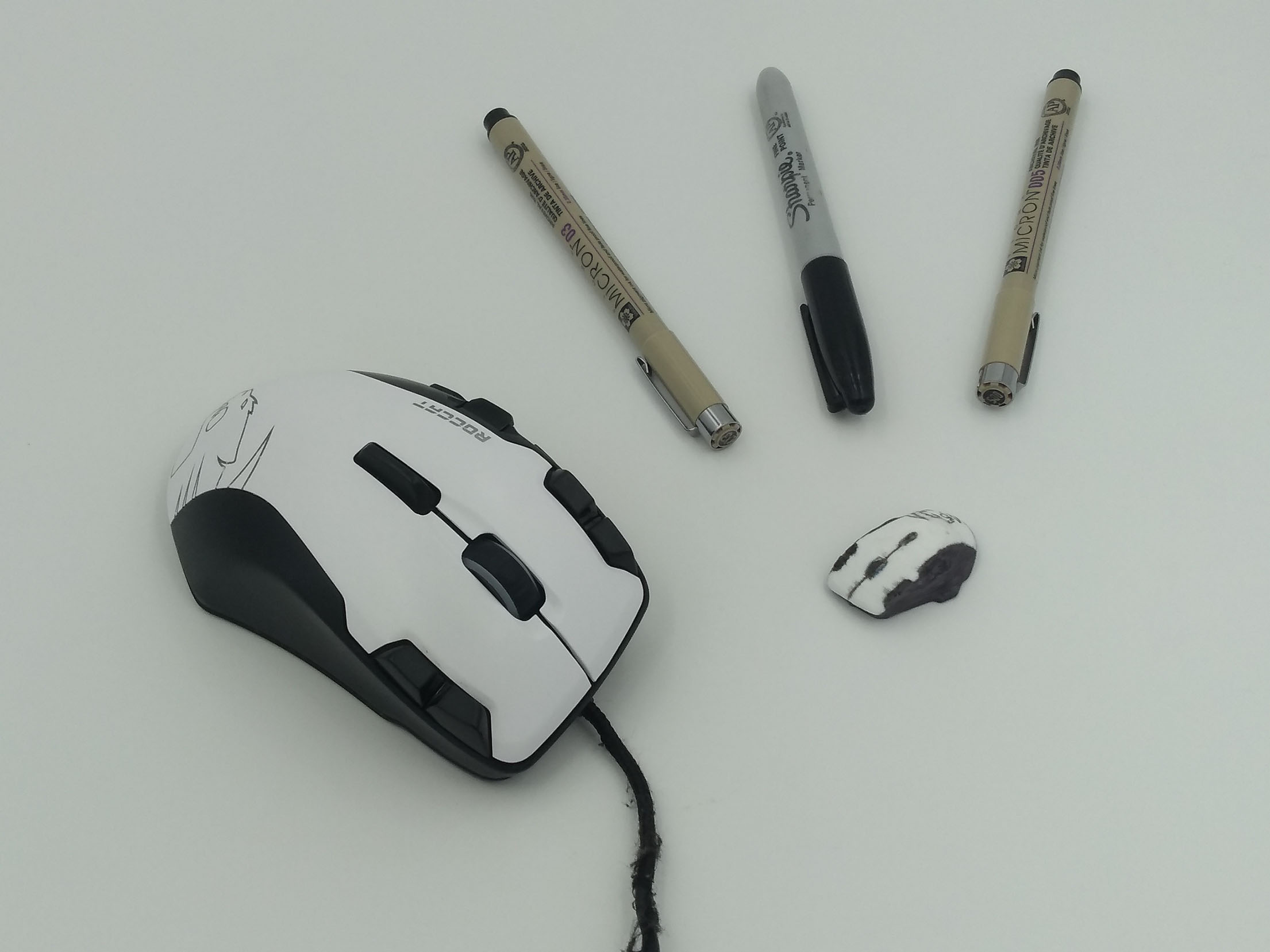
This week I scanned and 3D-printed my computer mouse, and 3D printed a custom car badge.
The group documentation can be found here.
Group work
In a group with other students in my lab, I 3D-printed a test peice to determine the tolerances of our lab's printers. We found a number of problems with the design of the test peice, but overall the prusa printers handled it quite well. I learned that files from Thingiverse are often not well designed. I already knew how to 3D print, and about how the printers could handle different geometries, so I didn't learn anything specific from the group assignment that I can reflect on. I gained a bit of experience in finding creative ways to measure dimensions.
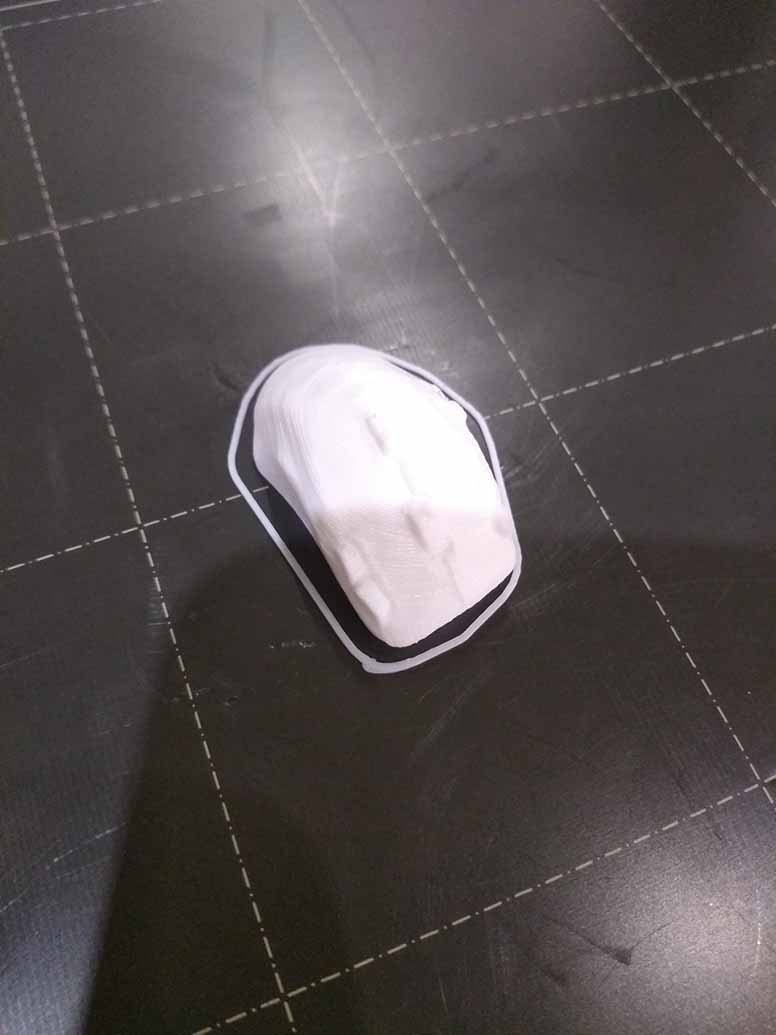
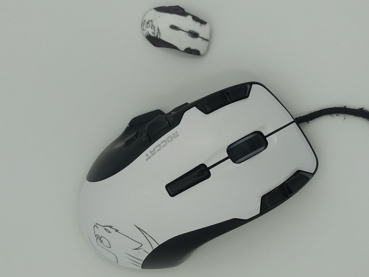
3D-scanned mouse
3D object (download)
I used several different programs to create a miniature replica of my mouse.
Kiri Engine
I started by using an app on my phone called Kiri Engine to scan my mouse. This involved taking 70 pictures of my mouse from various angles and waiting a bit for their servers to process the images into a 3D model. I then downloaded the model as a .obj file, and sent it to my gmail account so I could open it on my computer.
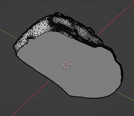
The model it created has some very serious problems. It looks like it has been dissolved with acid. I suspect that the highlights on the smooth plastic surface tricked the algorithm into seeing topography that wasn’t there. I assumed that the multiple angles of viewing might be able to account for this, but it failed. I think in the future I will look for Neural network based algorithms, as I know some have far surpassed this level of accuracy.
It is conceivable that if I had set up the lighting situation better I could have gotten a better result. Some of the scans Kiri Engine advertise are very impressive, but I not sure I can recomend it.
Blender
With the file on my Laptop, I opened up Blender, and made a render of the model to better show the distortions and imperfections. The Blender file doesn't have anything that the stl file doesn't, so I'm not going to post it here. You can import the stl file into blender.
I started off by removing the parts of the model I didn’t need. I only wanted a model of the mouse, so I went into edit mode, selected all of the vertices of the table, and deleted them.
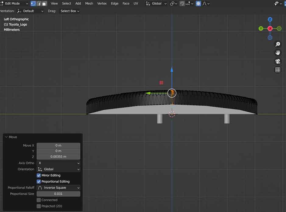
Press-fit connector
Next I went into sculpt mode and started fixing up the model. I used the draw tool to fill in some of the pits, and the smooth tool to flatten out some of the problematic geometry. I used the flatten tool in lieu of the smooth tool in places where I wanted the geometry to end up flat. I also used the sharp draw tool to carve the seams in the plastic. This whole process took several hours, as there was a lot of geometry to fix, and some of it I had to sculpt from scratch.
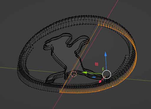
Once I was satisfied with the shape, I went back into edit mode, and used the bisect tool to cut a line at the bottom of the mouse. I then created a face from those points. Unlike what this screenshot might suggest, there were still some jagged edges from points that were below the bisect line. The next step was to remove those.
The purpose of all this is to prepare the model for 3d printing, as it can’t be sliced if it isn’t a fully enclosed mesh.
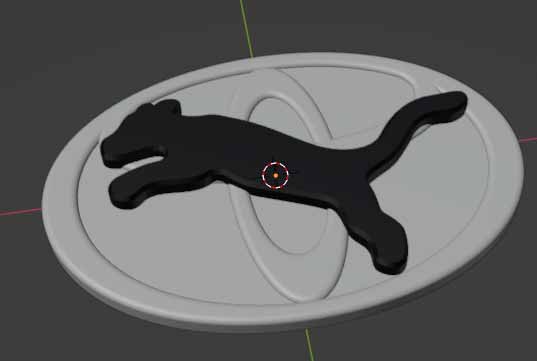
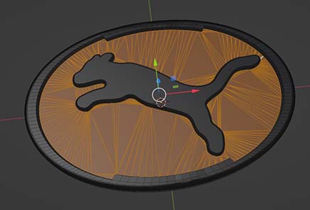
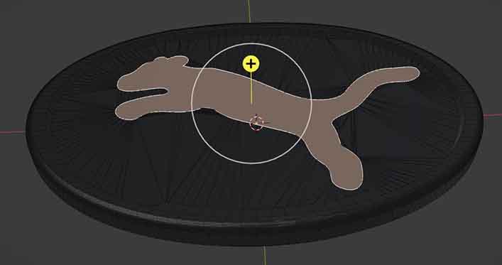
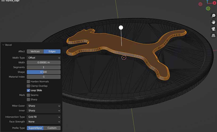
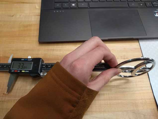
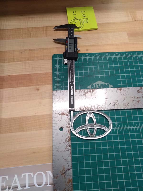
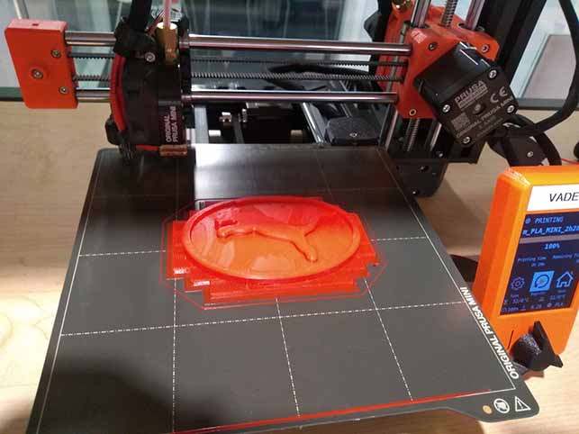
For this week's project I decided to make a curvy shape with undercuts that I believe would be difficult to make using subtractive manufacturing. I made a replacement for a broken Toyota car badge that has a jumping phuma in place of the Toyota logo. It has pins on the bottom that allow it to attach to the hood of the car.
Resources
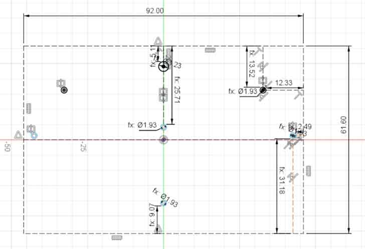
I started this project off with 3 design elements. The first is an old Toyota car badge that I measured and used as a reference. The second is a model of the Toyota badge that I found on Thingiverse. Unfortunately, the model I pulled from thingaverse is no longer available, so I cannot link to it.
The third is a vector art phuma that I adapted from an svg my sibling made.
It took me some time to decide which program to model this in. It involves curves that fusion 360 would have difficulty with, and precise measurements that would be awkward to do in Blender. I decided that I would use Blender to create the curved mesh part, and then move it into Fusion for the pins.
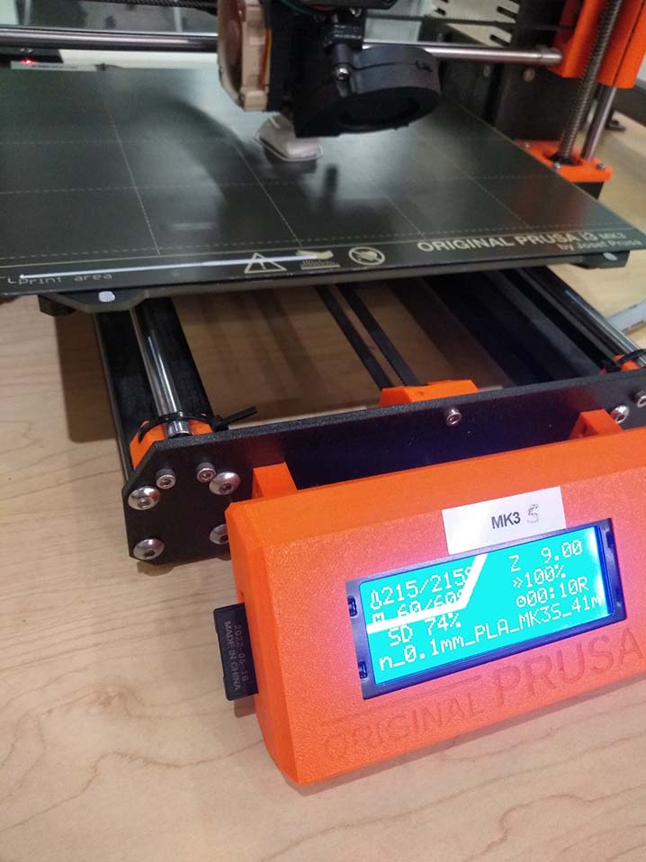
In prusa slicer I used paint-on support enforcers to try to give the pegs some room, and make it easier to remove the supports at the end. Unfortunately, this mesh needed a lot of support material, especially if I put the side that would be visible on top to keep it looking nice. The model would be hard to make subtractively because it has complex geometry on both sides of the object, and the cnc mill might have some trouble cutting all the way around the base of the pins because of the subtle curve. It is possible to make subtractively if you are very precise about flipping the piece over and cutting in the same place, but it makes more sense to make it additively.