These two weeks, I worked with my group of four to design a cuckoo clock. I designed the electronic system of the clock and the bird motion.
10. Mechanical Design and Machine Design
Group Assignment
As a group, our main plan was to build a lion clock, where a lion head opens its jaw every hour to reveal a chicken and then closes. However, the group members responsible of design did not have enough time to print their lion head design by the time they finished it. So we had to come up with a last minute solution, and I suggested going back to the idea that inspired the lion clock which was a cuckoo clock. As we'd already had the chicken printed, we only needed the house, which does not take a long time to deign as it is quite geometric with very simple details compared to a lion head, and it can be laser-cut in pieces and assmbled, which is way faster than 3d printing it. It did not make a difference for the electronics part, though, as the mechanism and program were the same. Group documentation can be found here.
Individual Assignment
Original Idea
My original idea was to use 12 RGB LEDs in a clock circle, where the green represents hours, blue represents minutes, and red represents seconds. I did succeed in making the porgrma work, but this resulted in around 100 wires that we did not have time to solder by the time the design was done. So I decided to use blue LEDs for hours only, which reduced the number of connections/wires by 75%. However, I will explain how I built both of these programs.
RGB LEDs
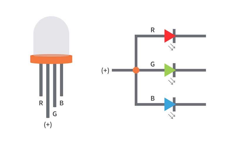
Each RGB LED consists of 3 LEDs enclosed in one bulb, so it has four different pins: one for ground and one for each LED. This results in 12*4=48 different pins, 36 of which need to go to the Arduino. But the Arduino has only 13 digital I/O pins, making it impossible to connect the LEDs directly to the Arduino. The solution to this problem was to use shift registers.
Shift Registers
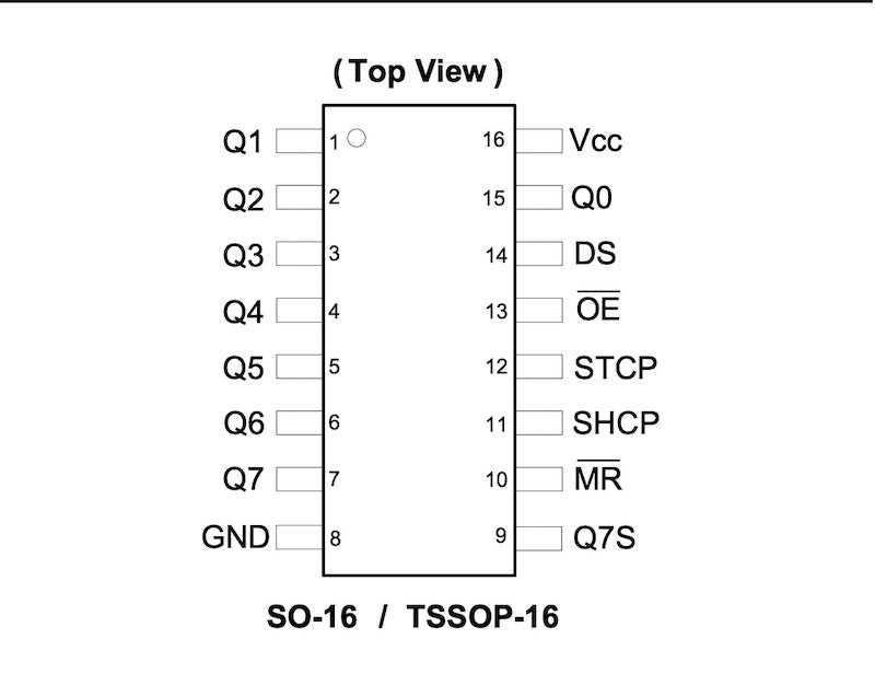
| Q0-Q7 | Parallel Data Outputs |
| GND | Ground |
| Q7S | Serial Data Output |
| MR | Master Reset Input |
| SHCP | Shift Register CLock Input |
| STCP | Storage Register CLock Input |
| OE | Output Enable Pin |
| DS | Serial Data Input |
| Vcc | Supply Voltage |
Image and Information Source: Manufacturer's Datasheet
A shift register is a type of digital cicuit using a cascade of flip-flops where the output of one flip-flop is connected to the next. They share a single clock signal allowing the data stored in the system to shift from one location to the next and leave the system once it passes though all locations. There are different types of shift registers used for different purposes. In this case, I needed to increase the number of outputs, so I used Serial-In-Parallel-Out(SIPO) type shift register called 74HC595. As its type suggests, this shift register receives input in series and outputs it in parallel, inreasing the number of outputs. The shift register has 16 pins defined in the table.
Circuit Diagram
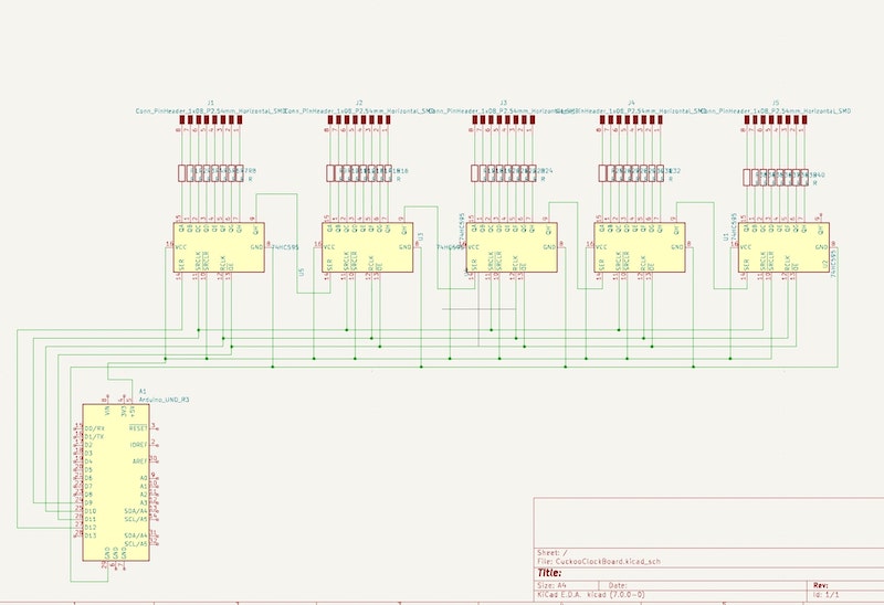
I used KiCad to draw the circuit diagram as the large number of connections can make things confusing without a diagram. First, I need 36 outputs for the 12 RGB LEDs I have, so I used 5 shift registers as each shift register has 8 output pins, resulting in last 4 pins unused. The fist step was to connect the first shift register to the Arduino pins as follows:
- GND on the Arduino to GND on the shift register to establish ground connection.
- 5V on the Arduino to Vcc on the shift register to supply the shift register with voltage.
- Digital I/O Pin 12 on the Arduino to DS on the shift register to send serial data from the Arduino to the register.
- Digital I/O Pin 11 on the Arduino to OE on the shift register. This pin controls the voltage state of all output pins, turning all HIGH when it is LOW and vice versa.
- Digital I/O Pin 10 on the Arduino to STCP on the shift register. The storage clock or latch clock sends stored data from the serial input to the outputs when it is HIGH.
- Digital I/O Pin 9 on the Arduino to SHCP on the shift register. The shift clock reads a new bit from the serial data pin everytime it pulses.
I then used a breadboard to connect all the 5 shift registers together. So I:
- connected all storage clock pins to each other to synchronize them.
- connected all shift clock pins to each other to synchronize them
- connected all Vcc pins to each other to make sure all shift registers are supplied with voltage.
- connected all the GND pins to each other to set the same ground for all shift registers.
- connected all OE pins together so the Ouput Enable Signal is the same for all shift registers.
- connected Q7S on the first shift register to DS on the second shift register and repeated the same for second-third, third-fourth, and fourth-fifth. This is to make sure serial data flow through all outputs.
- connected all MR pins to Vcc and thus to 5V of the Arduino. MR is the clear pin, and it clears all data stored in shift registers when its state is LOW, so I connected it to 5V to hold it HIGH and thus avoid data being cleared.
To connect the LEDs to the output pins, I needed more breadboard space, so I used a second breadboard. I used 36 220 Ohm resistors, one for each LED pin as the LEDs I used cannot stand the current provided directly from the Arduino. And finally, I connected all ground pins to the GND pin on the Arduino using hook-up wires.
Servo
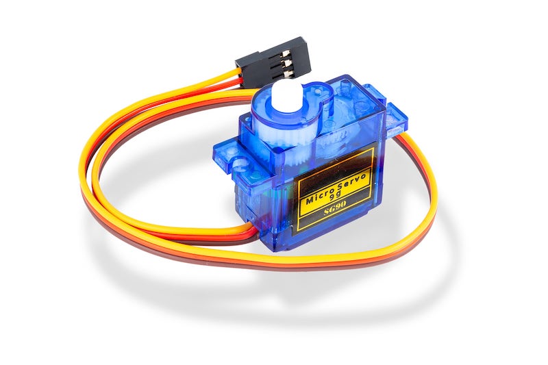
The servo needs to rotate 90 degrees every hour to move the chicken out and then go back to its original position. We used Servo Motor SG90 1PC, whic was light and small enough to fit into our clock yet strong enough to move the bird. First, I connected the GND and Vcc pins on the servo to GND and 5V on the Arduino, respectively, to establish power connection. Next, I connected the position pin on the servo to the I/O pin 6 on the Arduino to control the angular position of the servo.
Code
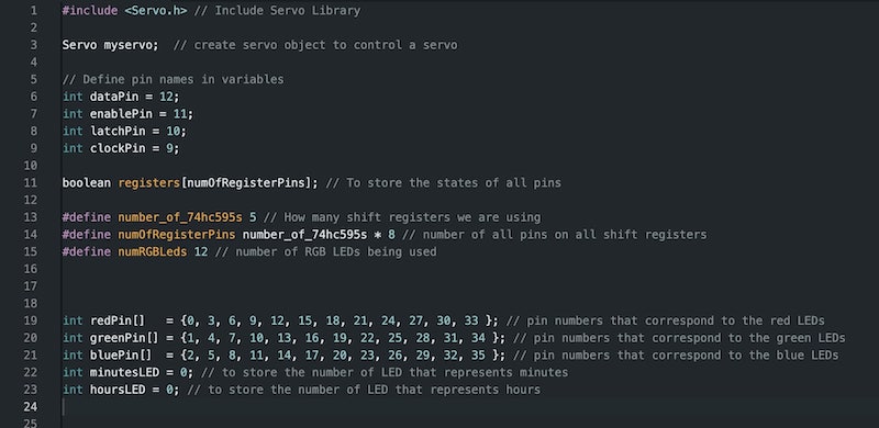
The first part of the program was to include the servo library and create a servo object to control the servo, define the rgister's pin numbers in variables, and define the numbers of pins, shift registers, and RGB LEDs. I also created a boolean array to store the states of the output pins. I needed 3 more arrays to store the numbers of pins that correspond to each color and two more variable to store the pins that correspond to minutes and hours LEDs.
Before the setup and loop functions, I needed the following two functions:
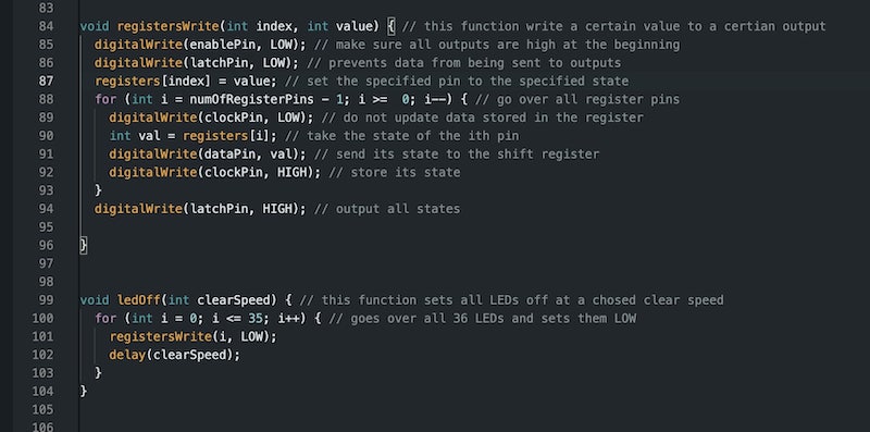
- registersWrite(index, value): it writes a LOW or HIGH state(value) to certain output pin(index). First, the function sets all outputs HIGH by setting OE pins to LOW to make sure all outputs are receiveing signal and sets latch clock to LOW to prevent stored data from being sent to outputs. It updates the specified output to the specified state. Then, it uses a for loop to store the desired states of all outputs in the shift register by pulsing the shift clock. And finally, it sets the latch pin to HIGH to send the stored data to the outputs.
- ledOff(ClearSpeed): it sets all LEDs to LOW with a ClearSpeed delay between each one. As shon in the screenshot, the function uses the registerWrite function to accomplish this.
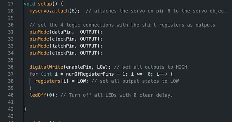
In the setup function, I used the attach() function to attach the servo to pin 6 and set all pins that go to the shift registers to outputs using the pinMode() function. Then, I set all the OE pins to HIGH to make sure all shift registers are receiving voltage and wrote a for loop to fill the registers array with LOW states. Finally, using the ledOff(0) function, I turned all LEDs off to make sure things start from scratch.
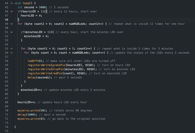
In the loop function, I used three for loops as follows:
- The inner for loop repeats 12 times, once every five seconds, and updates the states of the LEDs every five seconds.
- The second loop contains the inner loop, and it repeats five times, once every minute. Once we get out of this loop, the minutes LED moves to the next LED and five minutes have passed.
- The outer loop repeats 12 times, once every 5 minutes. Once we get out of this loop, we move the hours LED to the next LED as one hour has passed. Also, it is now time for the chicken to move, so we move the servo position 90 degrees, wait a second, and then mover baack to original position.
The if statements in the loop make sure the hours and minutes LEDs move back to the first LED once they go over all LEDs.
Video
Here is a video of the RGB clock. Notice that the red LED is supposed to represent 5 seconds, but in order to demonstrate the function faster in the video, I changed the delay time to 1 millisecond.
One LED clock
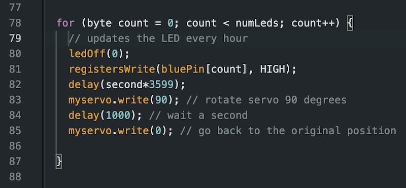
To change the clock to one blue LED, I had to use only 2 shift registers as I needed only 12 outputs. The circuit and connections were exactly the same but with much less wiring and components. For the code, I only needed to change the loop function as I needed only one for loop now that updates the LED every hour. This significantly simplified my previous code.
Final Clock Video
THe video on the left shows the clock working. I was trying to change the code so that the blinking LED represents minutes and the always-on LED represents hours. However, I did not get this working yet. In this video the minutes LED works, but the hours LED does not. Again, to make the video faster. I changed a minute to 100 milliseconds.