This week, I learned how to mill a circuit board from scratch and solder components on it.
8. Electronics Production
Group Assignment
For the group assignment, I had to do it on my own as our school, Wheaton College, was on Spring break. So I worked on studying the design rules on the Roland SRM20, the circuit board milling machine we have in the lab.
Important Milling Definitions and Parameters:
- Feed Rate: The linear velocity of the milling cutter relative to the workpiece. It can be expressed in different units, the most popular of which is the the distance per revolution. It can affect the quality of the production and the accuracy of the cut. Many factors should be considered when choosing the right feed rate such as the machine, the material, and the product to be cut.
- Plunge Rate: Similar to the feed rate, the plunge rate is the speed in the z driction. The ideal plunge rate varies depending on the bit used and the material being cut. It is always important to not plunge ata high speed to prevent the bit from breaking. Also, it should be consistent with the feed rate to make sure the cutting is smooth and the bit does not blunt.
- Depth of Cut: As its name suggests, this parameter specifies how deep into the material the machine will cut. It usually depends on the design type and objectives. For circuit boards, it is enough to remove the copper layer to prevent conductivity between different trace wires. And for holes and outline, it is important to not cut deeper than the thickness of the board as this may break the bit.
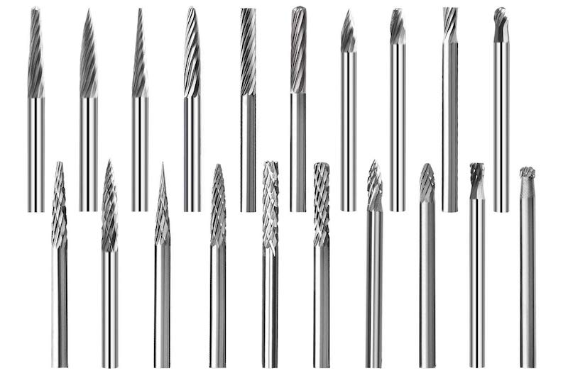
- Tooling: For our machine tooling, we only have control over the size of the copper sheets and the bit used. In our lab, we only have 6in*4in copper sheets, limiting the size of the board we can cut. For the bits, we most commonly use 1/64th of an inch diameter for milling traces and 1/32nd of an inch diameter for milling outlines because traces require higher precision. There are also bits with different head shapes used for different purposes, such as the ball nose which is used for curved cuts. On the left is a picture that shows different bits.
Individual Assignment
Design
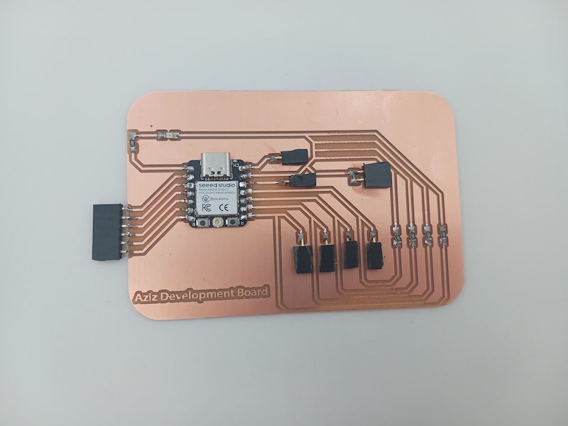
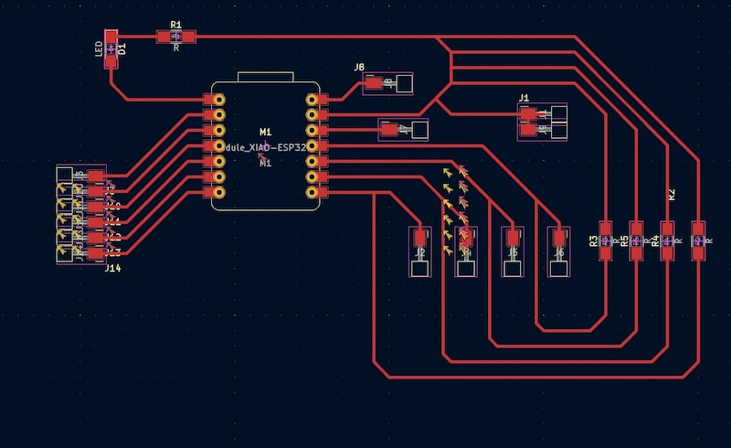
In week 6, I designed a board, but I was not satisfied with the design as I wanted the board to be bigger and wanted surface-mounted components instaed of through-hole ones. I also added pull-down resistors for 4 I/O pins to pull the input voltage down to the ground to prevent an undefined state at the input when no device is connected. In addition, I changed the the trace width from 0.25 mm to 0.5 mm as I wanted to avoid any bad connections. I used KiCad, and I followed a similar process as in week 6. I ended up with this PCB.


To mill the board, I exported it as an SVG file and opened it in Adobe Illustrator. First, I created a 6in*4in canvas on Adobe as that is the size of the copper sheets we have in the lab. Because the milling machine mills the traces, holes, and outline at seperate stages, I created the following five layers in Illustrator:
- White Background: I created a white rectangle with size equal to that of the canvas to serve as the background for black traces and holes.
- Black Background: I created another rectangle with the same size to serve as a background for the edge cuts or the outline since it needs to be white.
- Traces: Here, I inserted the the svg file I had exported from KiCad as these are the traces of my board.
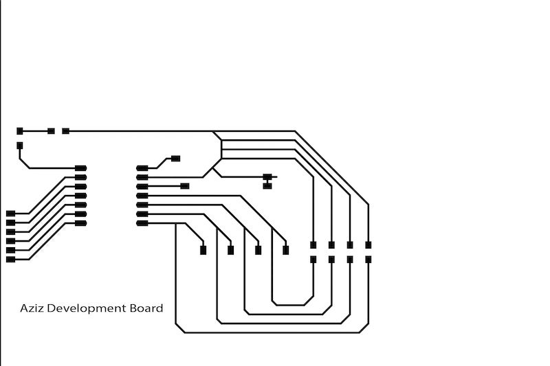
- Edge Cuts: I drew the outline of my board by estimating how big I wanted it to be based on the size of the traces.
- Holes: Finally, I copied the holes to this layer. But I decided not to cut them later as I realized they were not necessary.
Then, I exported the edge cuts and traces as two seperate png files making sure the right background is selected for each.
MIT mods
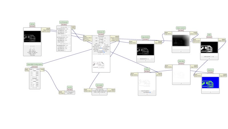
To generate the rml files that the machine needs to mill, I used MIT mods website. I opened a server program for Roland SRM20 png. I started with the traces by selecting the traces png file and then inverting the black and white as the machine cuts around what is white. In the set PCB defaults window, I chose mill traces(1/64), and in the Roland SRM20 milling machine window, I set the speed to 10 and x,y, and z to 0 to set the origin at the bottom-left of the file. And I created a new server module and selected file/save to save the file to my computer. I repeaed the same steps for the edge cuts except that I did not have to invert it and that I selected mill outline(1/32) instaed of mill traces(1/64) as this time we are going all the way through the baord.
Milling and Soldering
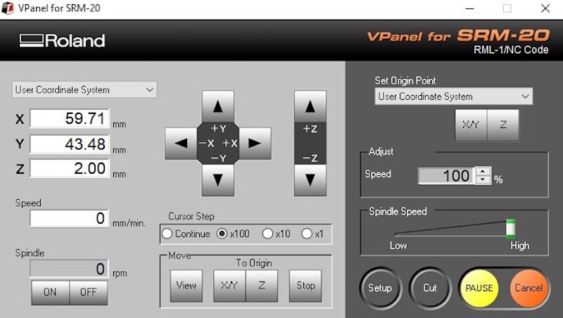
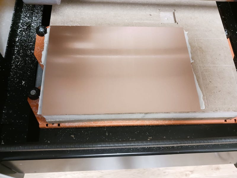
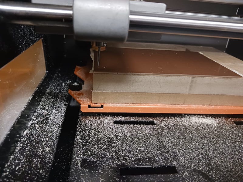
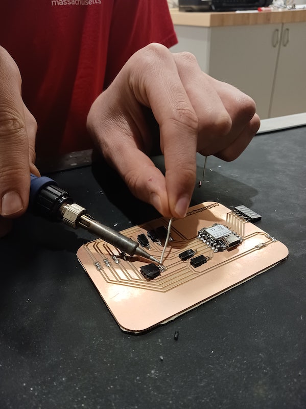
On Roland SRM20, I started by changing the end mill to the 1/64th end mill as traces require high precision. Then, I used double-sided tape to stick the copper sheet on the machine bed so that it does not move during the cutting process. Using the SRM20 software control panel, I moved the end mill to the bottom left and set the origin there. Next, I clicked on cut and selected my traces rml file and clicked on output. It is important to start the traces before the edge cuts to makes sure the board does not move during the traces milling. Once done, I changed the end mill to the 1/32nd end mill as edge cuts require less precision and repeated the same steps for the edge cuts file. Then, I vacuumed the copper dust and moved to the slodering stage.
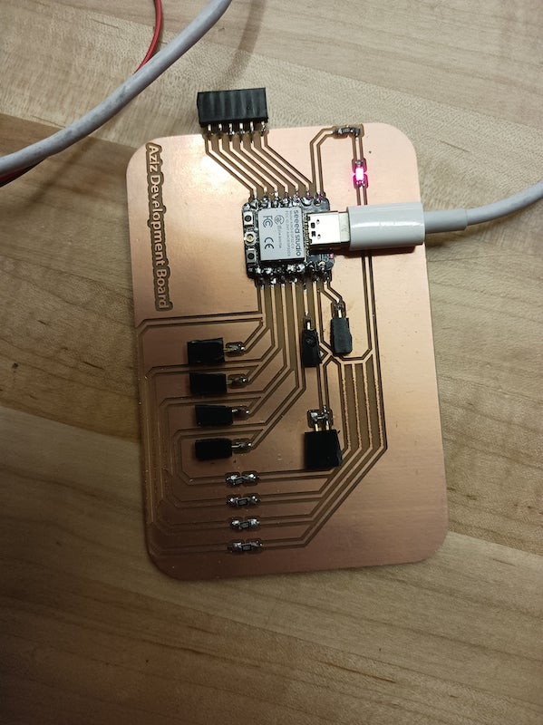
I set the temperature of the soldering head to 700 Fehrenheit and used leaded irond solder to solder the the ESP board, resistors, LED, and pin sockets on my board. Then, I sent a code to the ESP to blink the built-in LED to make sure my connections work.