4. Embedded Programming
This week, I worked with my group to compare the performance and development workflows for two architectures using the Arduino development environment. The group documentation can be found here. For my individual assignment, I programmed Arduino to receive data from an accelerometer chip and turn on a certian LED based on the tilt angle of the accelrometer.
Arduino and wiring
I already have prior experience with Arduino, so I did not have to look through the datasheet again. I started implementing my idea immdiatetly
First, I collected the following components:
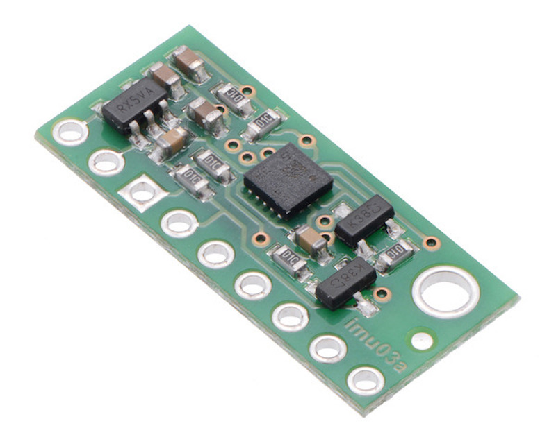
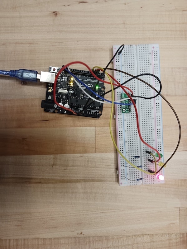
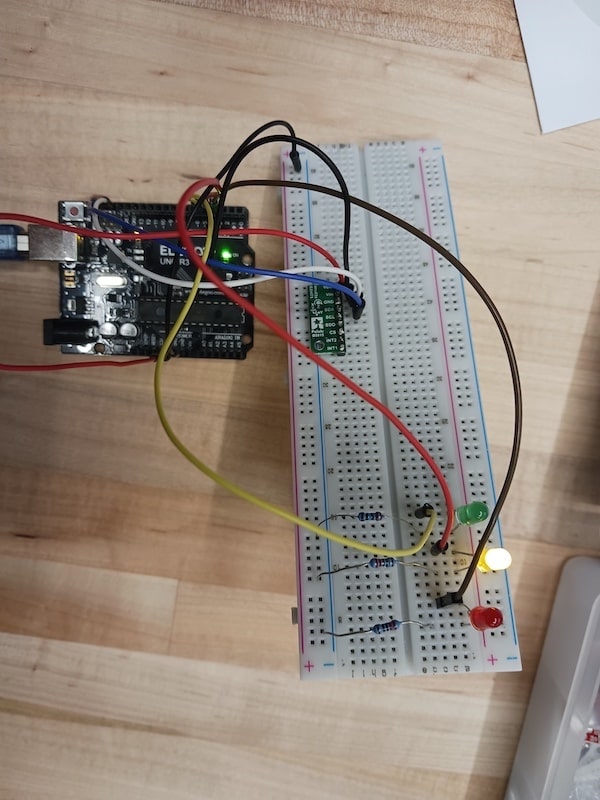
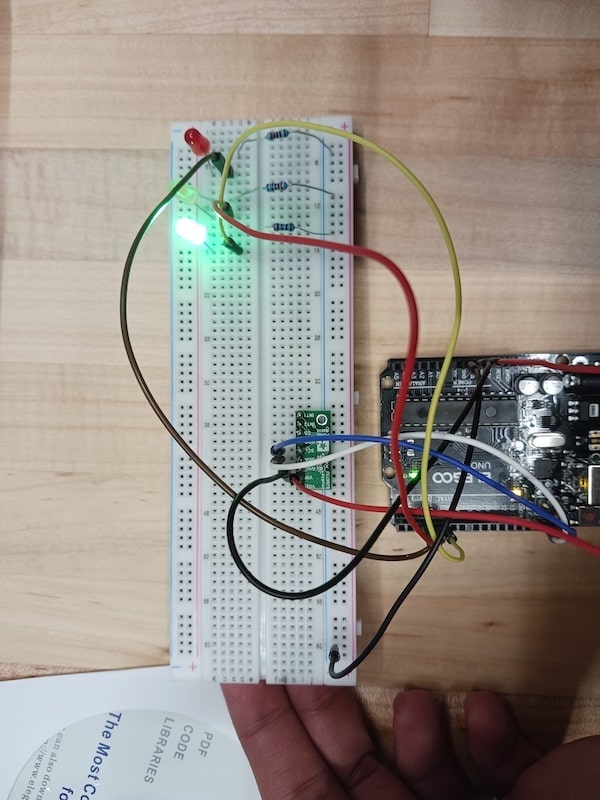
First, I hooked up the legs of the accelerometer to the breadboard and used 4 different wires to connect it to the arduino. I used the following wires:
Next, I plugged the three LEDs into the breadboard and used wires to connect the positive sides(the longer legs) to pins 3, 4, and 5 for red, yellow, and green, respectively. For the negative sides of the LEDs(the short legs), I used three 220 ohm resistors and hooked them so that they connect the short legs of the LEDs to the negative(red) row of the breadboard, fromw which a wire goes to GND pin on the Arduino. It is important to note that it does not matter whether the resistors are connected to the long or short legs of the LEDs since a full electric cicuit will be creacted either way.
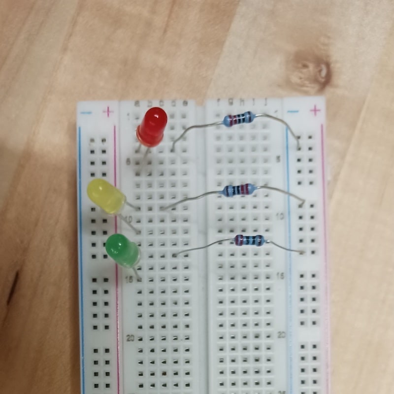
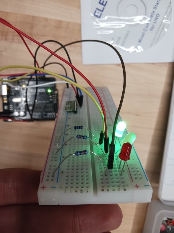
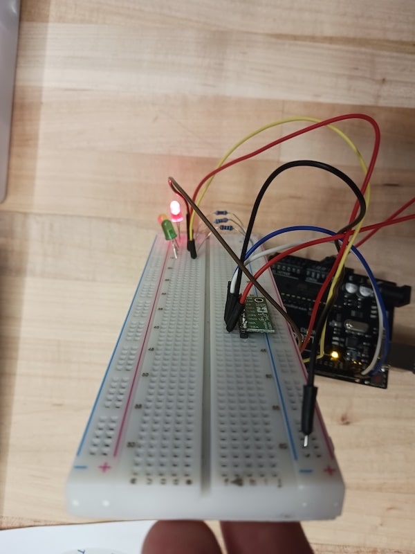
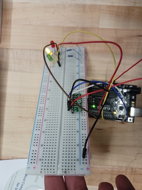
Now, my circuit is complete and it looked like this:
Arduino IDE and Code
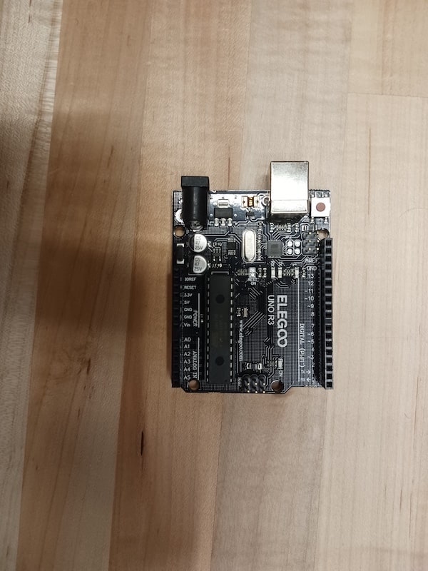
As the circuit is complete, we need to program it now. First, I plugged the Arduino USB Type C cable into my Mac(I needed a Mac USB adapter as Mac does not have built-in UBS ports). I opened Arduino IDE, the main software used to send code to the Arduino. To make sure the Arduino IDE recognizes the Arduino UNO, I navigated to Tools/Board and selected Arduino UNO and to Tools/Port and selected the port that says Arduino UNO in it.
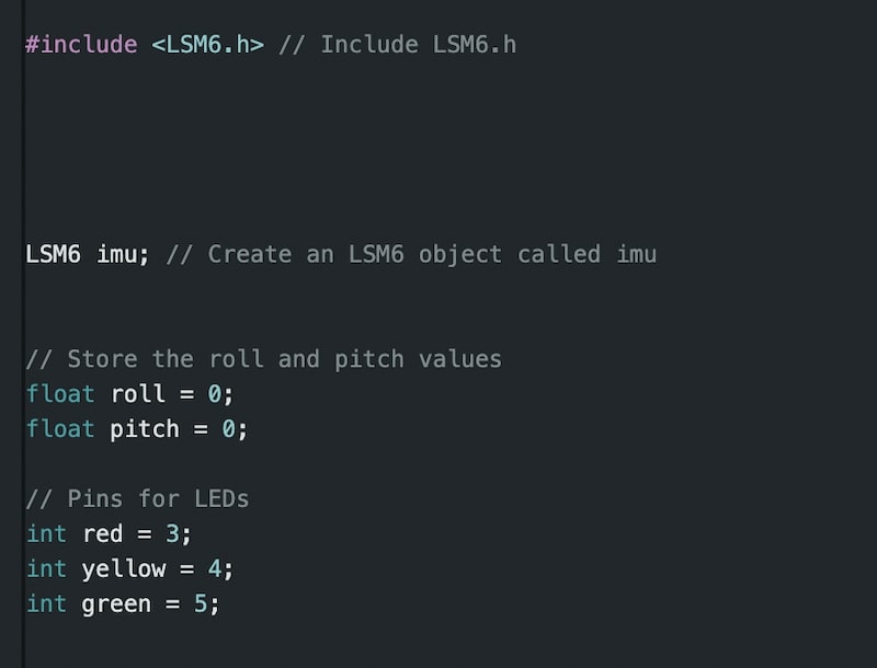
Next, I created a new file under the File/New tab to start writing the code. First, I included the LSM6 Library, the library that is designed for this accelerometer in particular. I had already had it installed, so I did not need to do that again. Then, I created an object of the class LSM6 in the libraray. Next, I declared the valiables I will need later in the code. Variables roll and pitch will store the tilt angles of the accelerometer around the X-axis and Y-axis, respectively. And variables red, yellow, and green store the pin number of each LED.
 y
y
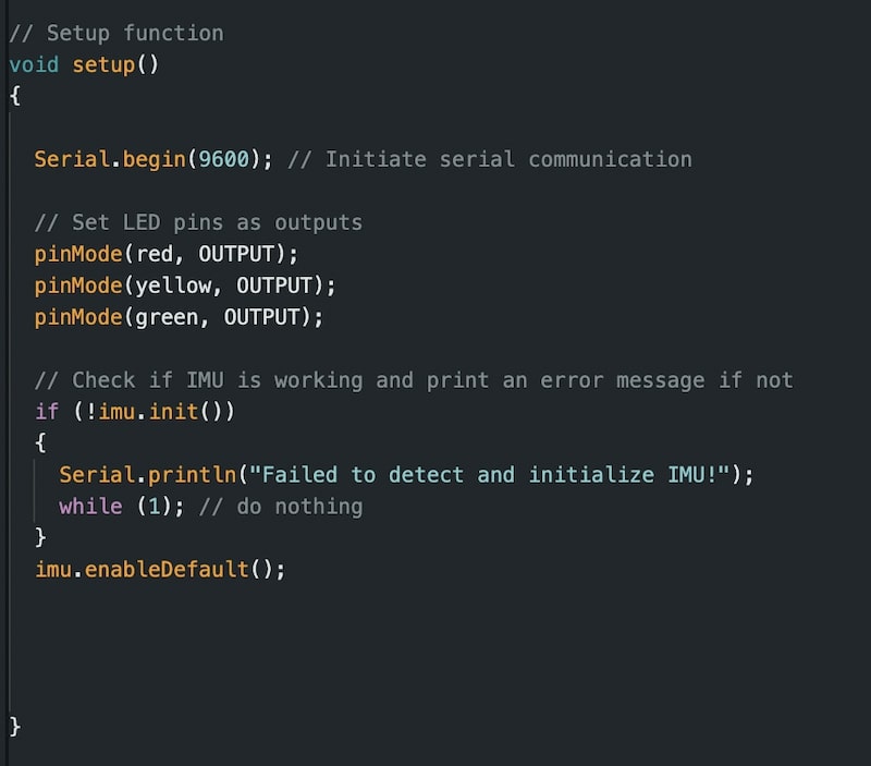
In the setup function(where the code is executed once only at the start of the program), I strated the Serial connection at a speed of 9600 bits/second to enable Serial Monitor to display data read by the accelerometer. Then, using the pinMode() function, I set the red, yellow, and green pins to outputs as I will be sending commands to them instead of receiving from them. Then, I wrote and if statement that checks if the accelerometer is working and halts the program if not.
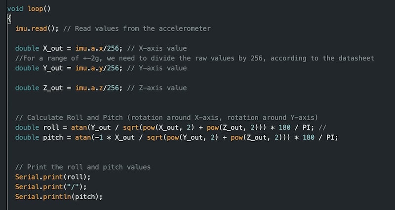
In the loop function(where the code is repeated continuously), I first used the read() method from the LSM6 imu object to read data from the accelerometer. This accelerometer chip in particular has a Gyroscope in it, so I can read 6 possible values from both the accelerometer and the gyroscope. For my case, I need the values from the accelerometer only as they are enough to compute the roll and pitch. I stored these three values into X_out, Y_out, Z_out variables and divided them by 256 for a sensitivity range of ±2g(where g is gravity constant).
Now, we need to compute the roll and pitch based on these values. I looked at this Freescale Semiconductor Application Note and found these formulas:
Now, I wrote three if statements to check the angle of roll to determine which LED to turn on. See the angles in the image below:
Now, the code is complete and ready to send to the Arduino. I clicked on the top left arrow to send the code to the Arduino, and once I did, I got the following results: