Overview
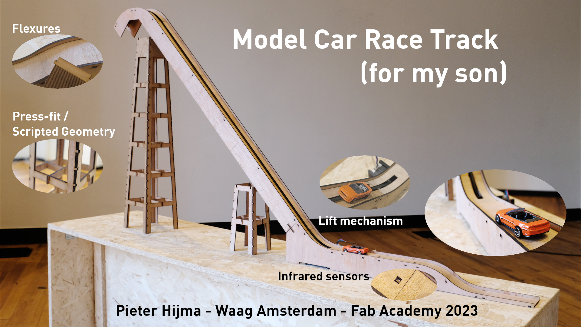
The Model Car Race Track for my son is a press-fit, laser-cut track with flexures and a lift mechanism that is actuated by cars being driven onto the track with infrared laser sensors. Unfortunately, I couldn't complete it as much as I wanted, but the main mechanism works more or less and my son will love this version as well!
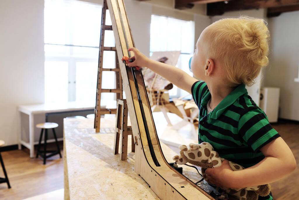
My son playing with the track:
Switching Projects
During the regular weeks of Fab Academy I haven't been able to work constistently on the first final project I anticipated, a device that warms my eye lids. The topics were just so interesting and I now understand that I did too much work during the weeks, making the final project harder and harder.
In short, I hardly worked on my final project during the weeks and this has several reasons: The week assignments were already very time consuming and there was simply not enough time to work on the final project. Additionally, the final project I chose was quite complicated in the beginning. For example, in the second week, I hoped to be able to finish the 3D model of the final project, but I only managed to do the outer body. At that time, it was very hard to imagine how to proceed, because I didn't know about the other assignments yet. This resulted in "being stuck" at this stage of the final project. Finally, you would hope that your final project starts to become more concrete and interesting as the program proceeds, but this didn't happen for me. In the end, I think I lacked motivation to really work on it.
Finally, in the end, I preferred to make something nice for my son. Since he loves model cars and plays with them all the time, I decided to make him a race track, similar to something I created in Week 3 . The old description of the final project is still archived .
I decided to switch to Model Car Race Track project at a very late stage, which meant that three weeks before the project presentations, I had almost nothing done. I was fully aware of the comments of Neil that by that time (and this was already weeks earlier that he said this) you should have a 3D design, etc. I don't see how I could have managed that with both the old project and the new project. I think this only works if you have a very clear final project in mind, such as Samson had with his animatronics.
Anyway, there was a lot to do in very little time, and I had quite some bad luck such as catching the flu and being sick for four days; holidays that limited my time because of not having daycare; the laser cutter's fume exhaust system breaking down, resulting in one day down-time and the replacement fume exhaust system requiring much more time inbetween jobs, where I am heavily dependent on the laser cutter; nice, but old plywood that was very curved requiring lots of experimentation with focusing, and making it hard to find good settings for the sheets, etc.
In Week 18 - Project Development I give a brief overview of the spirals, tasks, planning, together with some evaluation and reflection. Below I will discuss the specifics of the final project.
Experimentation Wood and Laser Cutting
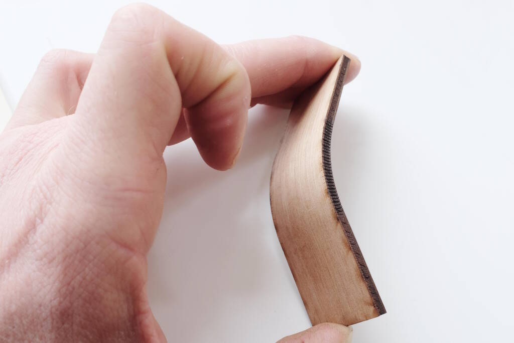
My journey started with testing the wood I had in mind, finding the right laser cutting settings and experimenting with flexures. I used hardwood plywood sheets that were found at the attick of the Waag. They were a bit old, but they had a great look.
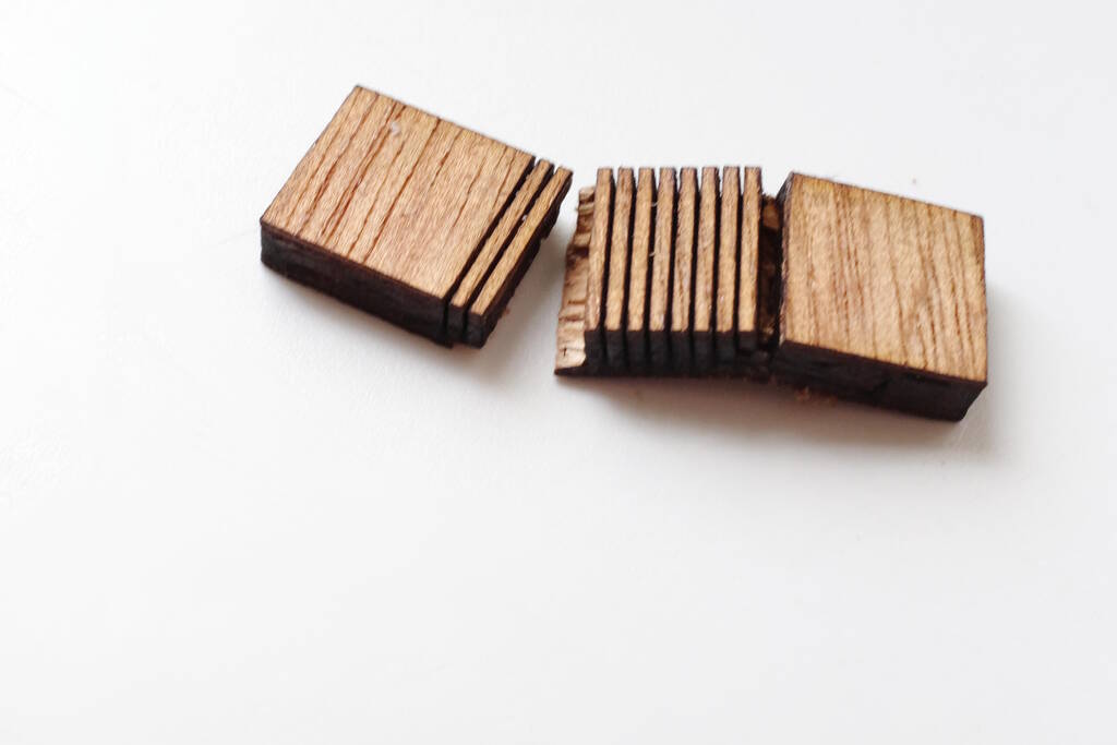
I needed to find a setting for cutting and for engraving such that I could bend the wood. This is a failed attempt:
After quite some experimentation, I found the following settings:
| Type of cut | Speed (mm/s) | Power | Minimum power |
|---|---|---|---|
| Cutting | 60 | 100 | 20 |
| Cutting | 90 | 50 | 20 |
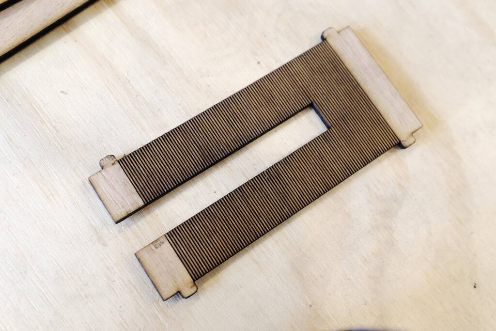
Unfortunately, there was still some scorching, but it was a good starting point. For creating the curves in the wood, I used spacing of 1 mm:
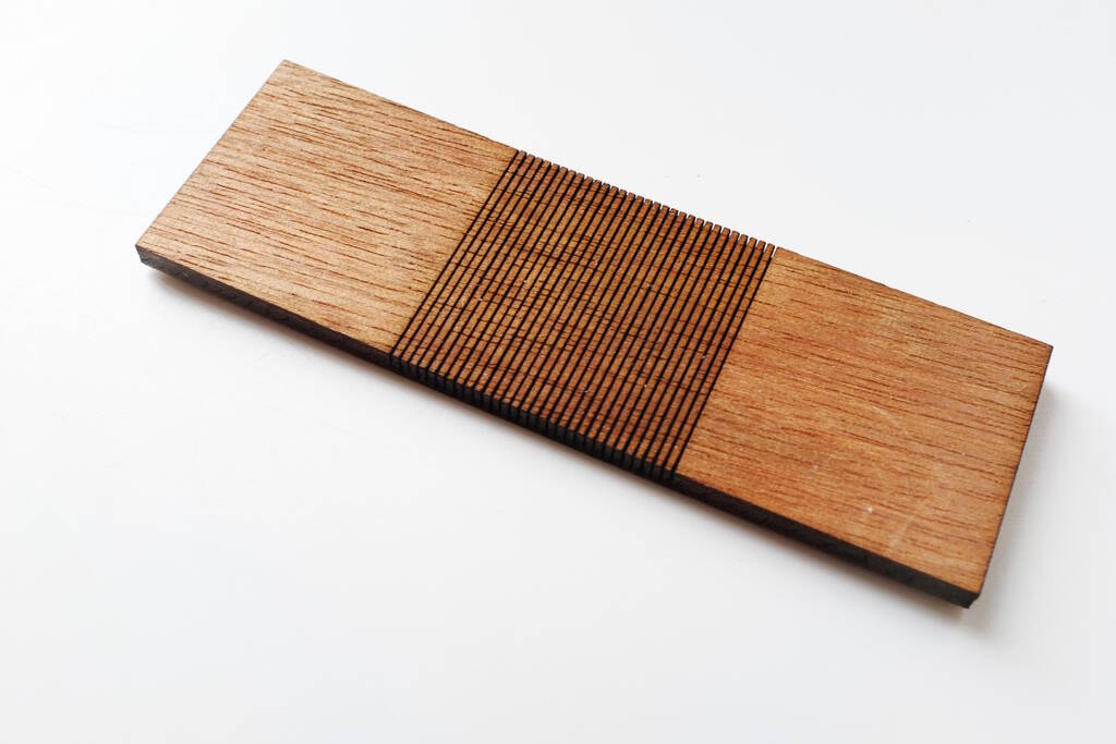
The piece bent:
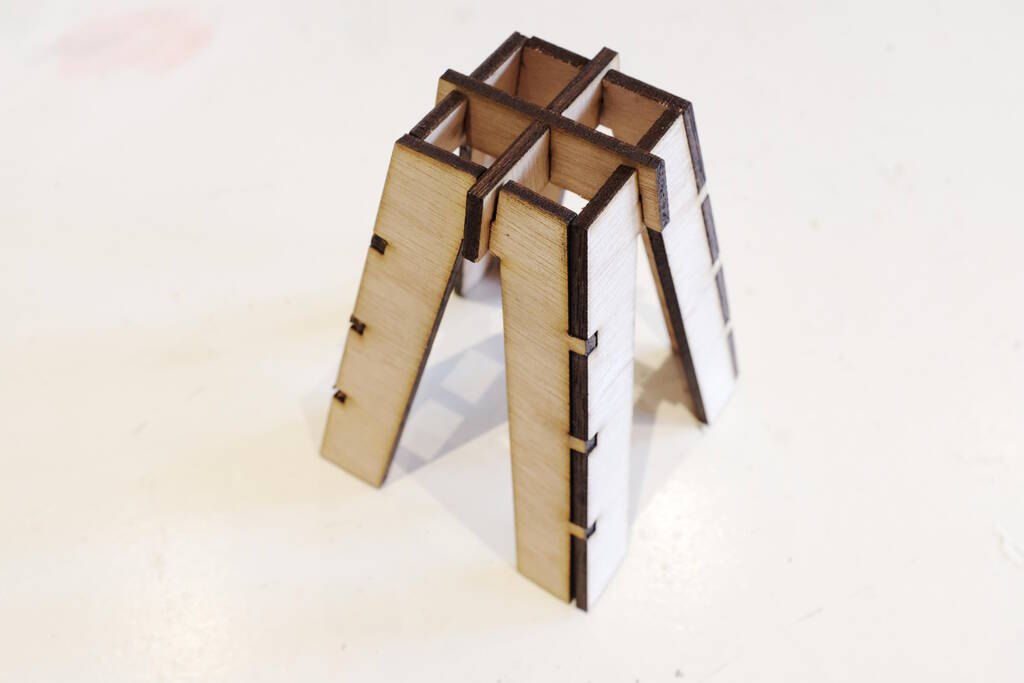
Pillars for the Track
Since I want an elevated track, I need something to rest the track on, so I designed pillars for that. The pillars are created from scripted geometry, which is one step beyond parametric geometry. It means that I can create custom geometry with properties that I can adjus. In this case, I can create a pillar that allows me to adjust the height. Automatically, cross bars and several levels will be created as shown in the video below:
The code to pull this off is quite complicated but it provides a high degree
of flexibility. The most important code is that of the leg of the pillar.
To give an indication of how this works, you can see in the code below that I
created a property
Height
and then to compute a shape, I first define
a set of points giving them names where I use an encoding for distincting
bottom and top, left/right, and outside/inside. After having defined all the
points, I can create edges from them. From the edges, I create a wire, from
which we can create a face, and then we extrude the face with the thickness
of the wood.
class LegPillar:

    def __init__(self, obj):
        obj.Proxy = self
        obj.addProperty("App::PropertyFloat", "Height").Height = DEFAULT_HEIGHT
        obj.addExtension('Part::AttachExtensionPython')

    def computeShape(self, obj):
        if obj.Height == 0:
            return

        compensatedTickness = THICKNESS_WOOD / math.sin(ANGLE_SIDE)
        height = heightPanel(obj.Height)

        # points
        # B/T: base / top
        # L/R: left / right
        # O/I: outside / inside
        pBLO = mkP(-widthBase(obj.Height)/2, 0)
        pTLO = mkP(-WIDTH_TOP/2, height)
        pTRO = mkP(WIDTH_TOP/2 - compensatedTickness, height)
        pBRO = mkP(widthBase(obj.Height)/2 - compensatedTickness, 0)

        # edges
        edgesConnectorsLeft = computeEdgesConnectors(obj, pBLO, pTLO, LEFT)
        edgesSlot = computeEdgesSlot(obj, pTLO, pTRO)
        edgesConnectorsRight = computeEdgesConnectors(obj, pBRO, pTRO, RIGHT)
        edgesLegs = computeEdgesLegs(obj, pBRO, pBLO)

        edgesLevels = computeEdgesLevels(obj)

        edges = []
        edges.extend(edgesConnectorsLeft)
        edges.extend(edgesSlot)
        edges.extend(edgesConnectorsRight)
        edges.extend(edgesLegs)

        # wires
        wOutline = mkW(edges)
        wHoles = list(map(mkW, edgesLevels))

        wires = [wOutline]
        wires.extend(wHoles)

        # faces
        f = Part.Face(wires)

        # solids
        # checked, is right
        e = f.extrude(App.Vector(0, 0, THICKNESS_WOOD))

        obj.Shape = e

    def onChanged(self, obj, prop):
        ''' Do something when a property has changed '''
        if prop == "Height":
            self.computeShape(obj)
The code below gives an indication on how to compute edges for, for example, the legs, computing some points, and combining them to edges. Note the mirror utility function that allows me to mirror similar points from left to right:
# pBRO: point bottom right outside
def computeEdgesLegs(obj, pBRO, pBLO):
    pBRI = mkP(pBRO.x - WIDTH_LEG, 0)
    nrHoles = round(heightPanel(obj.Height) / DEFAULT_HEIGHT) - 1
    height = DEFAULT_HEIGHT - WIDTH_LEG if nrHoles > 0 else heightPanel(obj.Height) - WIDTH_LEG
    dxTI = height / math.tan(ANGLE_SIDE)
    pTRI = mkP(pBRO.x - WIDTH_LEG - dxTI, height)
    pTLI = mirrorP(pTRI)
    pBLI = mirrorP(pBRI)

    edges = [
        mkE(pBRO, pBRI),
        mkE(pBRI, pTRI),
        mkE(pTRI, pTLI),
        mkE(pTLI, pBLI),
        mkE(pBLO, pBLI)]

    return edges
One of the first small pillars:
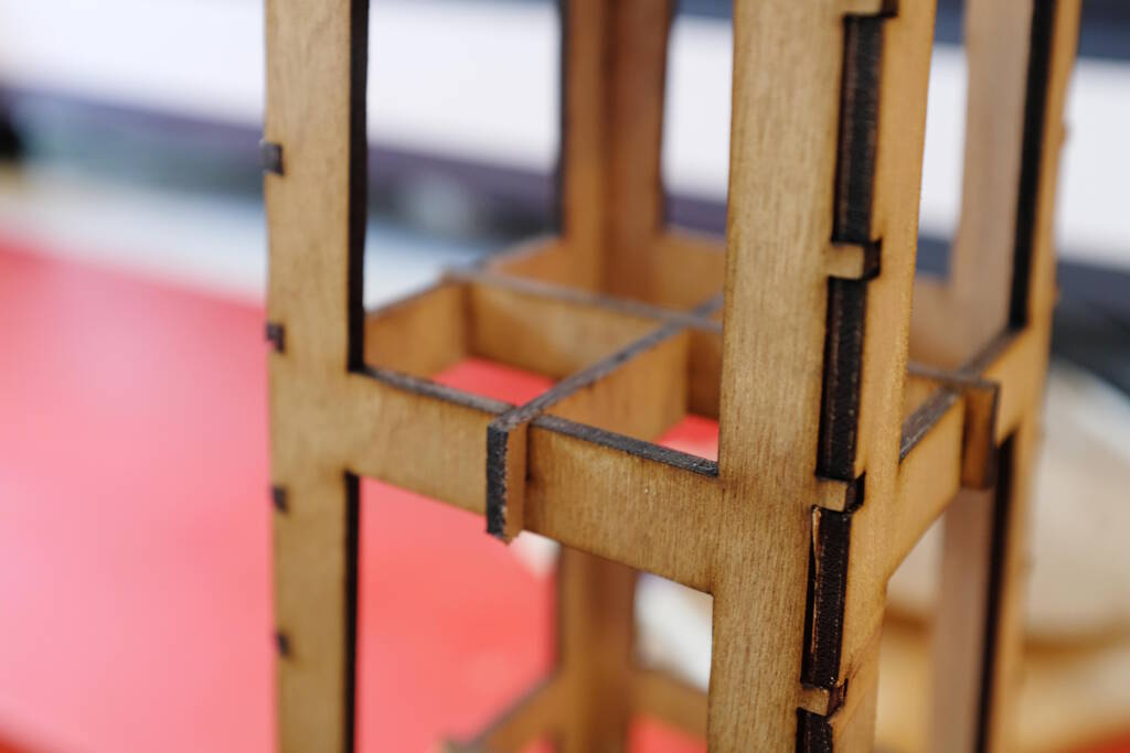
And a detail of the brackets for a larger one:
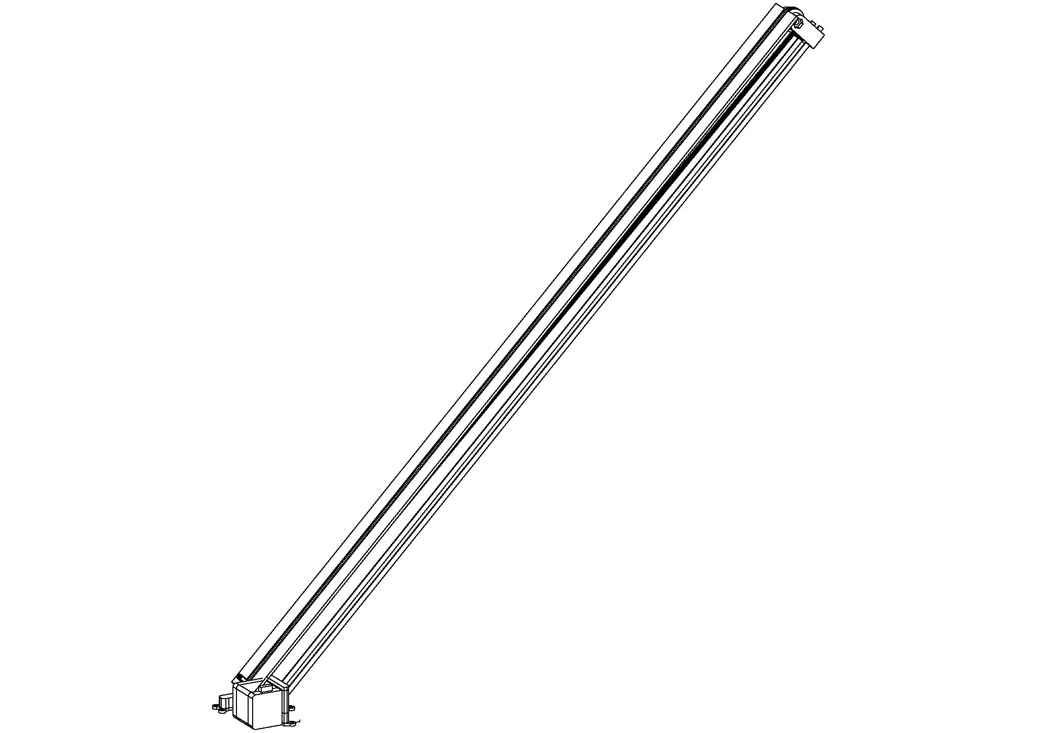
Modeling the Motor and Lift Mechanism
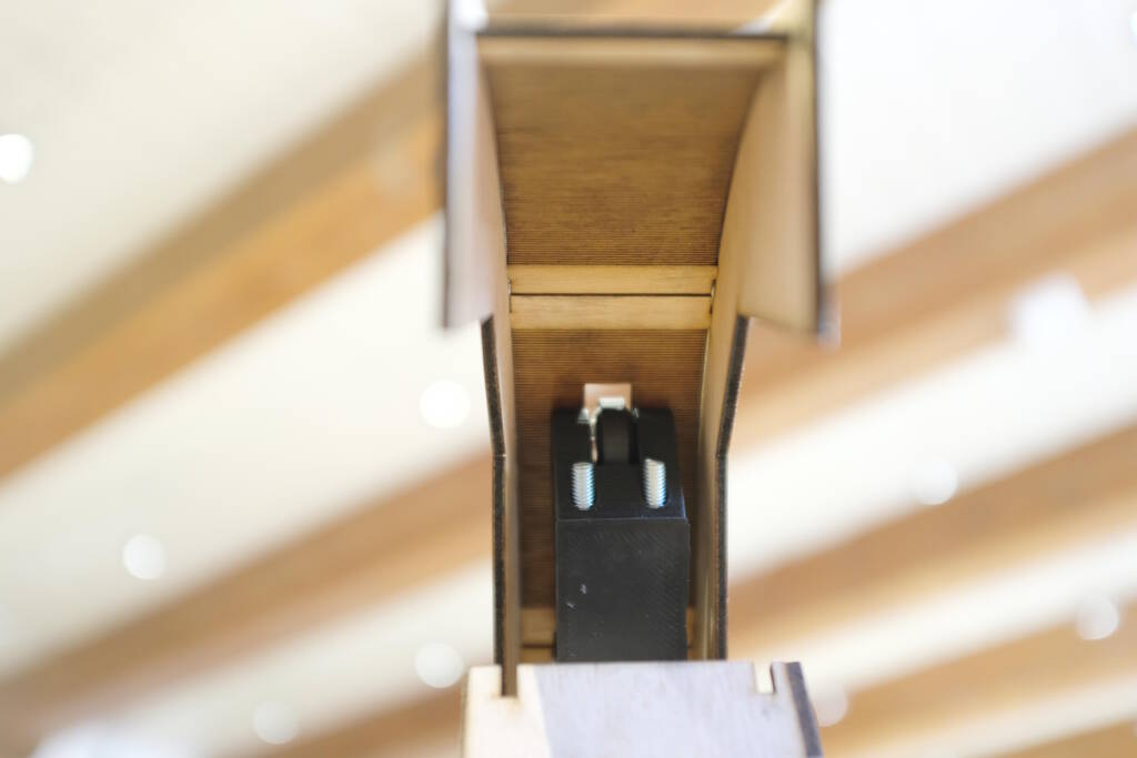
The next step was to think about the mechanism for the lift. The most promising solution I had in mind was using a belt tied together with a clip that can push the car up the track. I have a height of 60 cm in mind, which means that the belt is rather long, so I need a good way to tension the belt for it to work.
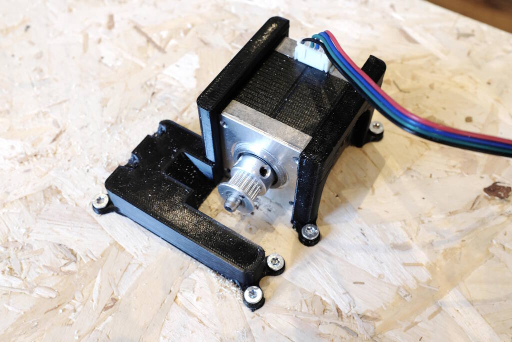
I bought two 1 meter long threaded M6 beams with wing nuts that allowed me to create a custom 3D printed part that I could tension with the wing nuts. Having decided on this, I wanted to design a bracket for the motor that would fit tightly around the motor for stability, and that would hold the beams in place to make sure that the belt was well aligned with the track.
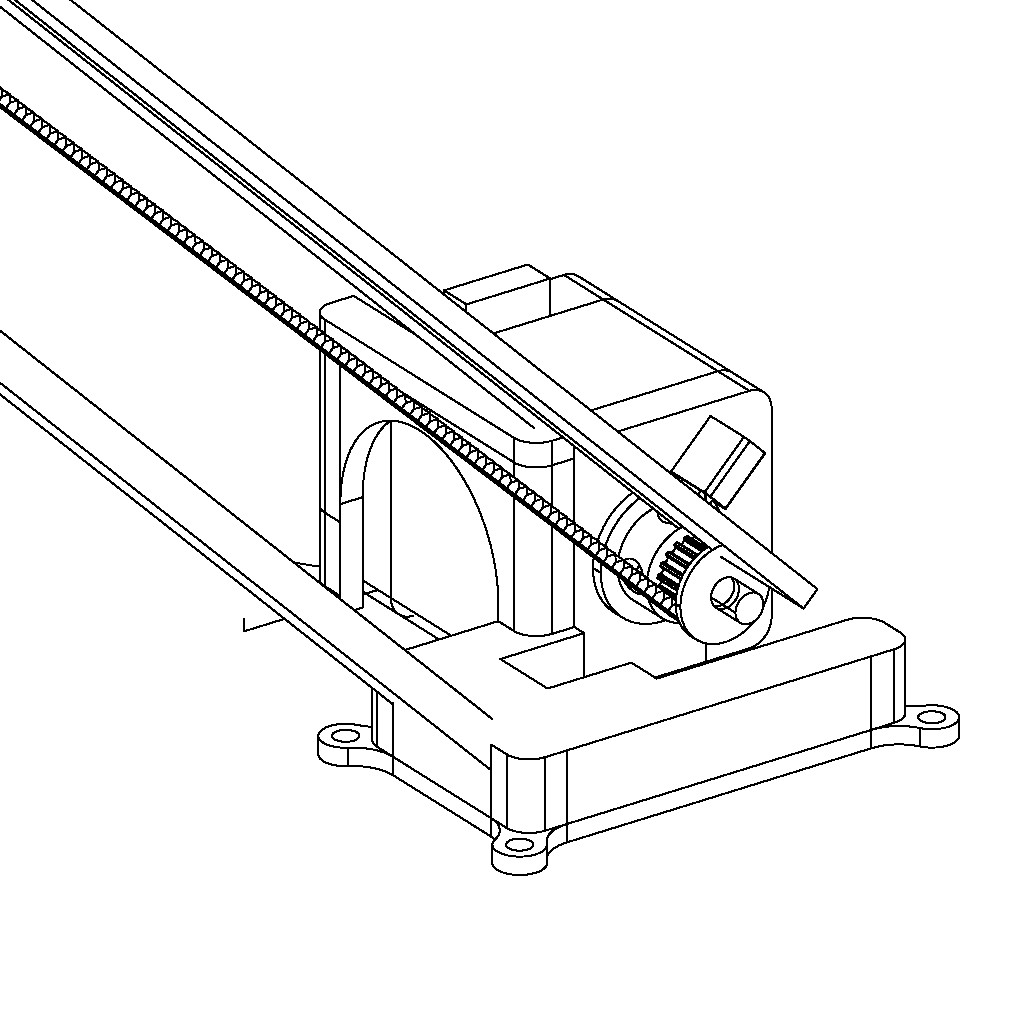
At this stage, the following was modeled: the brackets for the motor, the motor, the belt, and the bearings, and the threaded beams:
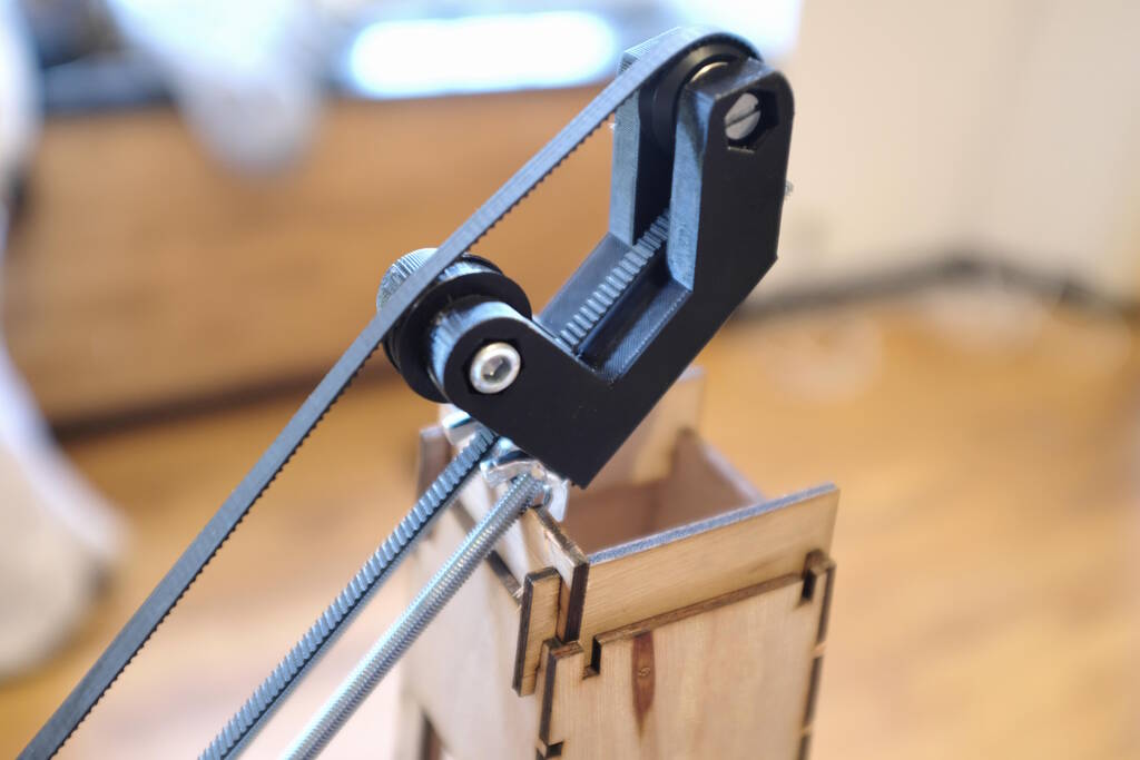
The motor, bracket, and belt in detail:
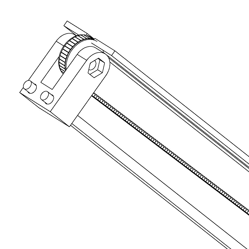
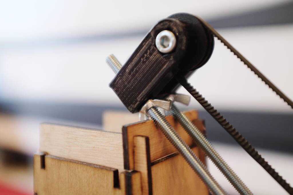
The top pulley in detail:
Car Sensor Electronics
The documentation of Nick Anastasia was very helpful and allowed me to design the board for the infrared car sensor without much challenges. The schematic is:

The PCB layout:

The BOM:
| Reference | Value | Footprint | |
|---|---|---|---|
| D1 | HIR11 | fab:LED_1206 | |
| J1 | Conn_01x04 | fab:PinHeader_1x04_P2.54mm_Horizontal_SMD | |
| Q1 | PT15-21B-TR8 | fab:Q_1206 | |
| R1 | 10 kOhm | fab:R_1206 | |
| R2 | 100 Ohm | fab:R_1206 |
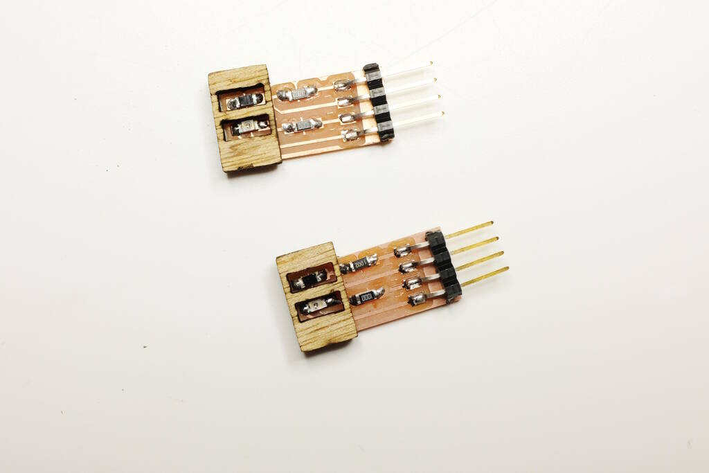
The resulting car sensor:
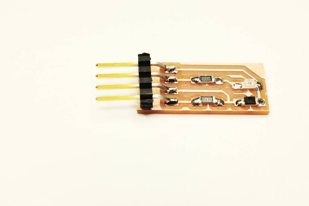
It turned out that the infrared LED shines directly onto the infrared sensor. To prevent this, I laser cut a wall between them:
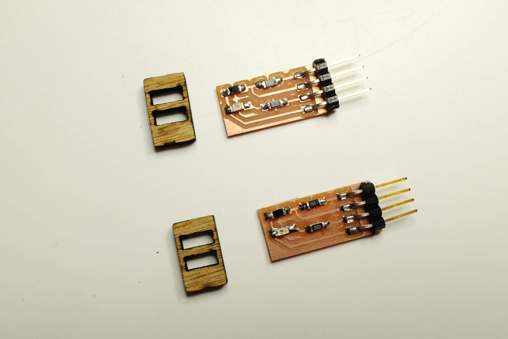
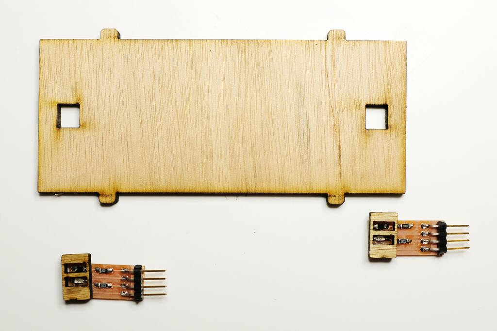
Assembled:
The track piece with pins and holes for the car sensors:
For the code, I wrote testing code for the sensor specifically. It maintains a running average to really be able to detect a difference in the situation. I defined a 20% difference to be significant enough for having detected cars. The code was inspired by what Nick Anastasia did, namely taking a number of samples of the infrared LED on and immediately measuring the light intensity. Then turning off the LED and measure the light intensity again. We then average this over a number of samples.
What I added myself is better naming, making a distinction between ambient infrared and infrared caused by turning on the LED. I'm then comparing with a running average, whereas Nick was comparing it to the number of samples which I don't really understand. Then based on the 20% threshold that I set I decide whether the sensor has sseen a car.y
The code with comments to explain:
#define FRONT

#ifdef FRONT
#define PIN_IR_LED    D1
#define PIN_IR_SENSOR D0

#else

#define PIN_IR_LED    D3
#define PIN_IR_SENSOR D2
#endif

#define NR_SAMPLES  100

#define NR_SAMPLES_AVG 50

#define DETECTION_FACTOR 0.2

void setup() {
   pinMode(PIN_IR_LED, OUTPUT);
   pinMode(PIN_IR_SENSOR, INPUT);
   Serial.begin(9600);
   delay(3000);
   Serial.println("starting up");
}

int messagedReady = 0;

int nrSamplesAvg = 0;
int sumAvg = 0;

int nrCarsDetected = 0;

void loop() {
  int valLED = 0;
  int valAmbient = 0;

  // take NR_SAMPLES samples
  for (int i = 0; i < NR_SAMPLES; i++) {
    digitalWrite(PIN_IR_LED, HIGH);
    delay(1);
    valLED += analogRead(PIN_IR_SENSOR);

    digitalWrite(PIN_IR_LED, LOW);
    delay(1);
    valAmbient += analogRead(PIN_IR_SENSOR);
  }

  // find the difference
  int diff = (valAmbient - valLED) / NR_SAMPLES;

  // we first take NR_SAMPLES_AVG to establish an average for the current
  // conditions.  The diff will be compared against this running average.

  if (nrSamplesAvg == NR_SAMPLES_AVG) {
    // we are ready to detect now
    if (!messagedReady) {
      Serial.println("Ready to detect cars");
      messagedReady = 1;
    }

    // determine the previous average
    float previousAvg = sumAvg / (float) nrSamplesAvg;

    // check if we detected something
    if (diff > previousAvg * (1 + DETECTION_FACTOR) ||
        diff < previousAvg * (1 - DETECTION_FACTOR)) {
      nrCarsDetected++;
      Serial.print("Car ");
      Serial.println(nrCarsDetected);
      delay(2000);
      // we don't count this in the average
    }
    else {
      // replace the previous average with the current value
      sumAvg -= previousAvg;
      sumAvg += diff;
    }
  }
  else {
    // we are still collecting samples for the running average
    nrSamplesAvg++;
    sumAvg += diff;
  }
}
3D Printing
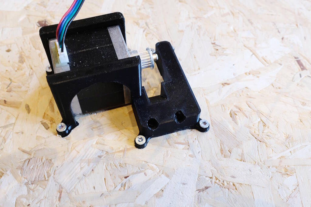
3D-printing is instrumental for this design. It allows me to create brackets for the motor that holds the motor down well, and precisely places the threaded beams in alignment with the motor and the track. In addition, it is important for the piece that tensions the belt.
The bracket for the motor with the holes for the threaded beams. Note that the brackets are designed such that there is enough room for dissipating the heat.
The first tensioner:
A later version of the tensioner that follows the track more:
Testing the Stepper Motor
Henk warned me that I might be disappointed with the speed of the stepper motors. I investigated and indeed stepper motors are not very fast. I assumed they would be quite fast because of my experience with the 17 Watt DC motor that had surprising power. I estimated stepper motors to be 12 Watt, so not as fast, but still quite some power. I now understand that the design is very different and that stepper motors have a very low RPM compared to DC motors.
To compensate for this, I experimented with a 24 V power supply that I retrieved from an old printer:
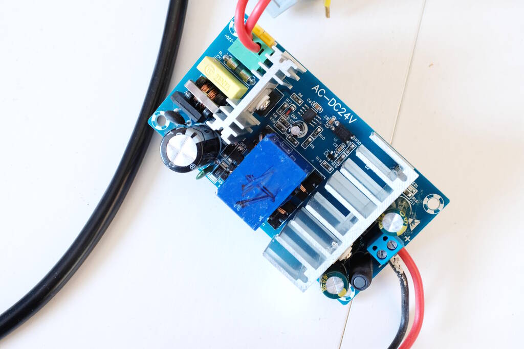
I managed to get it running:
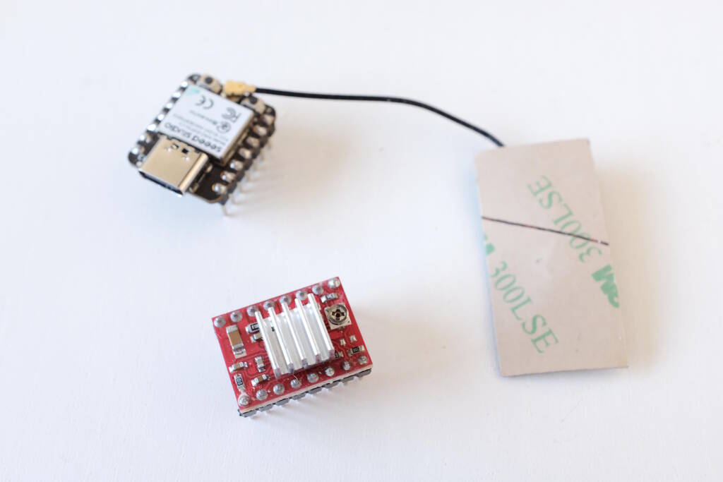
However, I wasn't very careful with the breadboard and connections. I accidentally touched a pin of the ESP32-C3 with 24 V leading to sparks and smoke, blowing up the microcontroller board and the stepper driver. I later blew up another stepper driver as well, most likely because I didn't have a capacitor to catch high frequencies.
I decided not to experiment any further before I had a proper board designed with all the measures in place to prevent these kinds of things such as capacitors. The stepper driver and ESP32-C3 that passed away:
Lift Electronics
The board that controls the lift and is connected to the two car sensors makes use of an ESP32-C3 because this gives me the possibility to connect the rotary platform and the camera system with a wireless connection. In principle, these three components are independent but if needed, I can connect them wirelessly with the ESP32 chips.
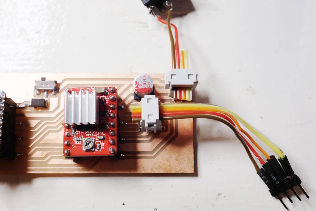
The Board
The board has a connector for 12 V, two connectors for the two car sensors, a connector for the stepper. It has a socket for the Pololu A4988 stepper driver and a socket for the ESP32-C3.
Because I need to be able to fine-tune the lift actuation based on the car sensors, I added a switch that either enables the ESP32-C3 to be powered from the USB-C connection or from the 12 V connector for stand-alone operation. This indeed turned out to be very helpful for fine-tuning and debugging. The pins for the stepper driver are chosen such that the tracks on the board are easy to route.
The schematic for the board is as follows:

The layout of the board:

The BOM:
| Reference | Value | Footprint | |
|---|---|---|---|
| A1 | Pololu_Breakout_A4988 | fab:Pololu_Breakout-16_15.2x20.3mm SMD | |
| C1 | 100 uF | fab:CP_Elec_D6.3mm_H6.1mm | |
| D2 | Diode_Schottky_MiniSMA | fab:SOD-123T | |
| J1 | Conn_Car_Sensor_2 | Connector_PinHeader_2.54mm:PinHeader_2x02_P2.54mm_Vertical_SMD | |
| J2 | Conn_Car_Sensor_1 | Connector_PinHeader_2.54mm:PinHeader_2x02_P2.54mm_Vertical_SMD | |
| J3 | Conn_Stepper | Connector_PinHeader_2.54mm:PinHeader_2x02_P2.54mm_Vertical_SMD | |
| J4 | Conn_12V | Connector_PinHeader_2.54mm:PinHeader_2x02_P2.54mm_Vertical_SMD | |
| M1 | Module_XIAO-ESP32C3_SocketSMD | fab:SeeedStudio_XIAO_SocketSMD | |
| SW1 | Switch_Slide_Top_CnK | fab:Switch_SPDT_CnK_JS102011JCQN_9x3.6mm_P2.5mm |
The Code
To fine-tune the distance of the belt movement and the timing of the
sensors, I wrote code that allows me to send commands. Below a video of me
trying to fine-tune the timing where I set the microstepping factor
f
, acceleration
a
, position
p
, and the speed of moving
the lift
m
. I can also set the delay between detecting a car and
activating the lift but this is not shown in the video:
The following code shows how the command interpreter is implemented:
void loop() {
	if (!questionPrinted) {
		Serial.println("Command: ");
		questionPrinted = 1;
	}
	if (Serial.available()) {
    String command = Serial.readStringUntil('\n');
    command.trim();

		String argString = command.substring(2);
		int arg = atoi(argString.c_str());

		if (command[0] == 'm') {
			stepper.setMaxSpeed(arg * microstepFactor);
			stepper.setAcceleration(acceleration * microstepFactor);
			Serial.print("speed: ");
			Serial.println(arg);
			runMotor();
		}
		else if (command[0] == 'p') {
			position = arg;
			Serial.print("position: ");
			Serial.println(position);
		}
		else if (command[0] == 'a') {
			acceleration = arg;
			Serial.print("acceleration: ");
			Serial.println(acceleration);
		}
		else if (command[0] == 'f') {
			int factor = arg;
			setMicroStepFactor(factor);
			Serial.print("microstepFactor: ");
			Serial.println(factor);
		}
		else if (command[0] == 'd') {
			delayFactor = arg / 10.0;
			Serial.print("delay factor: " );
			Serial.println(delayFactor);
		}
		else if (command[0] == 'c') {
			lift_car();
		}
		else if (command[0] == 't') {
			test_sensors();
		}

		questionPrinted = 0;
	}
}
The following code shows the inner working of lifting a car:
void lift_car() {
	// wait until we detected a car on the front sensor
	while (!detect_car(PIN_IR_LED_FRONT, PIN_IR_SENSOR_FRONT, &sumAvgFront, 0));
	int timestamp_front = millis();

	// wait until we detected a car on the back sensor
	while (!detect_car(PIN_IR_LED_BACK, PIN_IR_SENSOR_BACK, &sumAvgBack, 0));
	int timestamp_back = millis();

	// compute the time
	int time = timestamp_back - timestamp_front;

	// delay according to the factor set by the user
	delay(time * delayFactor);

	stepper.move(-DISTANCE * microstepFactor);
	stepper.runToPosition();

	// delay 3 seconds for moving the lift back
	delay(3000);

	stepper.move(DISTANCE * microstepFactor);
	stepper.runToPosition();
}
Designing the Track
The design of the track was far more complicated than I anticipated. Not only the pillars are complex (something I did anticipate), but also the other parts are complex. Firstly, there are many parts that are unique and custom because of the lift mechanism that has to be fit in. Secondly, curving the track pieces up and down resulted in complexity because I need to model both the curved version and the flattened version that mimicks how it comes out of the laser cutter. I need to compute the exact position of the pins to make the pieces work. Finally, the many parameters make the design complex.
To give an indication about the complexity: I have three files with parameters, in total over a 100 variables in five categories: constants, parameters, clearances, derived values, and measured values. There are four subdirectories with geometry: for the pillar, the motor, the timing belt, and the track. In total there are about 30 CAD files that are combined into an assembly file.
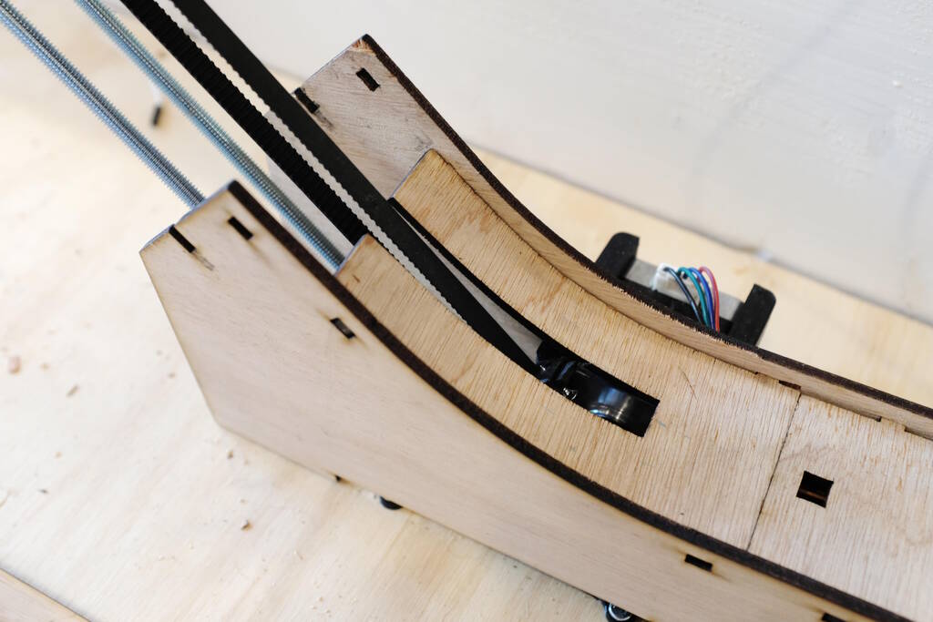
Track Pieces bending up
The most complex geometry was perhaps the rail that follows the curved track pieces. So, the ramp where the cars enter the track is as follows:

This geometry is used in the assembly to make sure that the pins match up with all the holes. However, to properly laser cut this piece, I need to "unroll" it and make it flat adding lines to engrave:

Then there is the rail or the side wall that should hold this ramp by means of the pins and slots. The sketch that defines the slots for the pins is very complex:
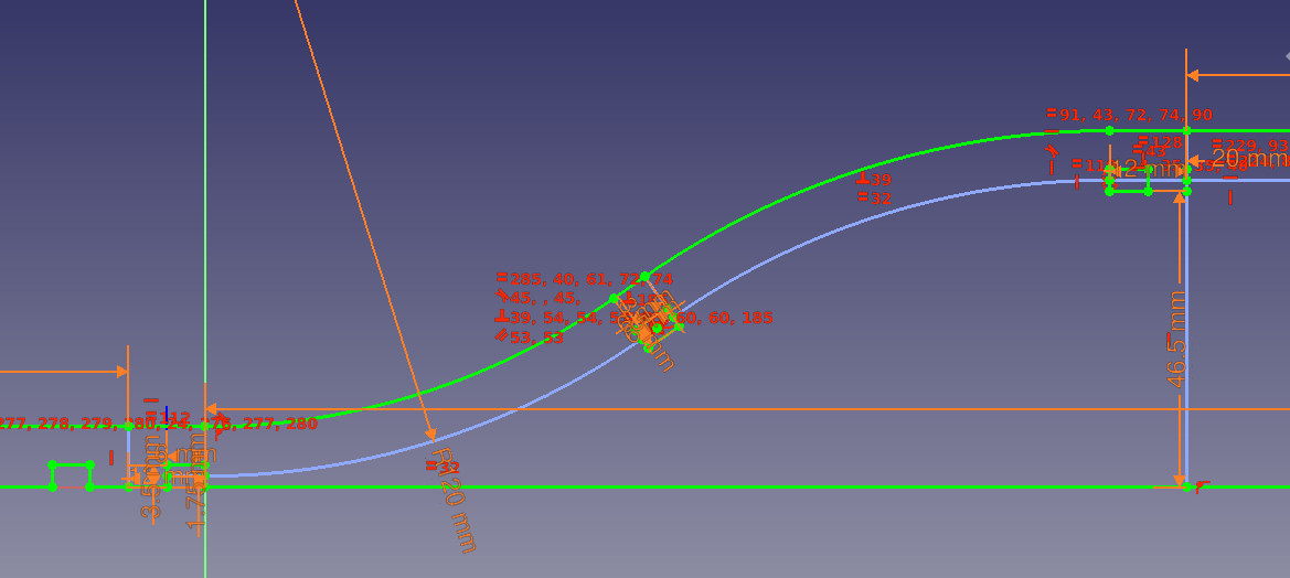
The blue line is the middle-line of the ramp, following the curves of the ramp. The slots have to be centered around this line, compensating for the clearance for the pins, making sure that the diagonal slot matches up perfectly with the middle slot of the laser cut ramp after applying the bending of the wood.
Making all this work is simply very complex and a small mistake will result in a situation where none of these parts fit. I deem myself lucky that I computed the distances correctly, so this didn't cost extra time.
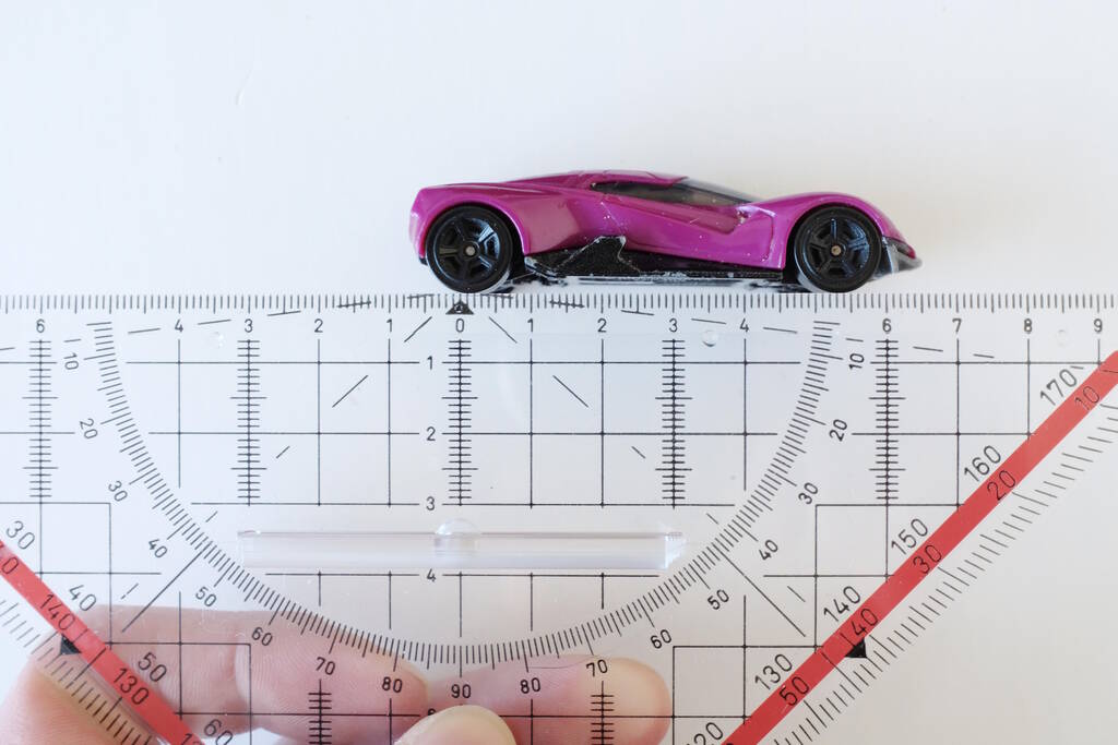
To determine the right radius of the curved track, I took a picture of one of my son's cars:
I then tried to find a radius that would work both ways:
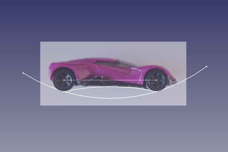
The radius I went for was 120 mm.
Laser Cutting
Laser cutting was interesting because the settings that I needed went all over the place, depending on where I would laser cut on the plywood sheets. The bed wasn't very leveled either and the wood was quite curved in some places. Recall that I initially started with the following settings, both with only one pass:
| Type of cut | Speed (mm/s) | Power | Minimum power |
|---|---|---|---|
| Cutting | 60 | 100 | 20 |
| Cutting | 90 | 50 | 20 |
In the end, I ended up with the following settings:
| Type of cut | # Passes | Speed (mm/s) | Power | Minimum power |
|---|---|---|---|---|
| Cutting | 2 | 33 | 100 | 20 |
| Cutting | 1 | 70 | 100 | 20 |
These were not the right settings for all the parts of the plywood sheet, but this gave me consistent results, albeit that the rims were burned more than I would like.
In the end, I became a master in weight distribution to find focus:
Integrate the Electronics
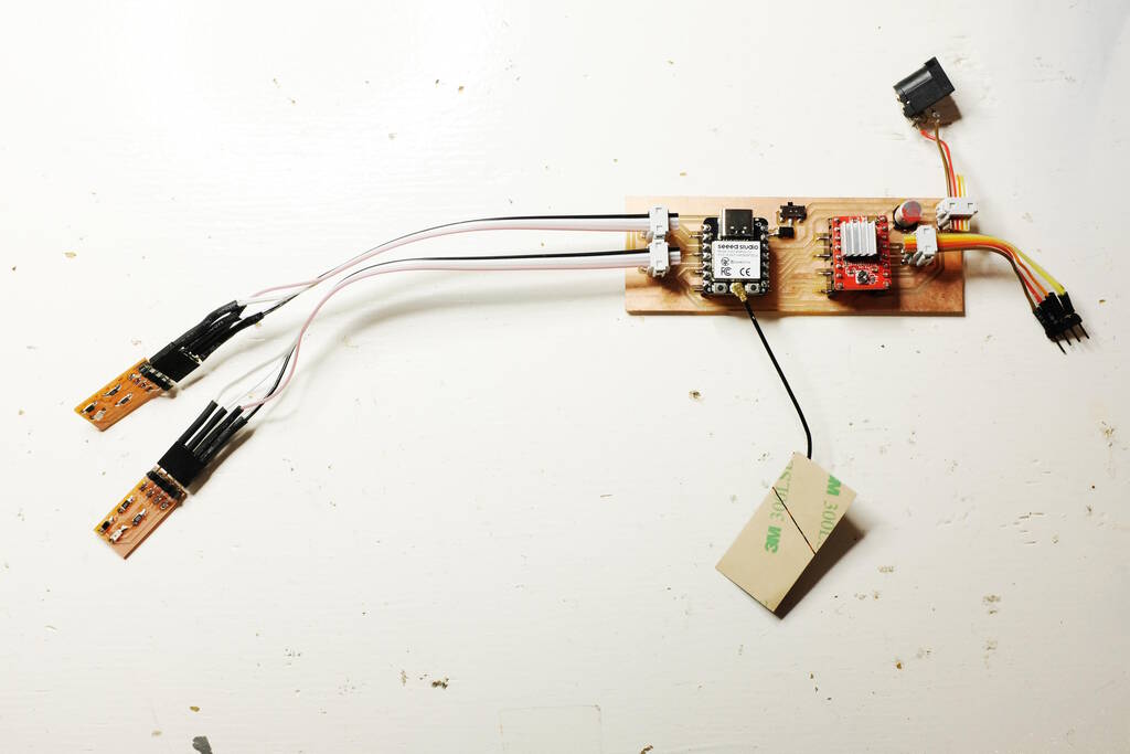
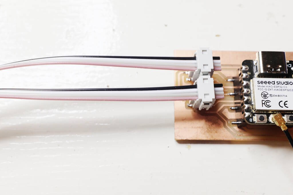
Because of the 2x2 connectors and the 12 V power supply, it is a good idea to document well how the cables should be connected:
First Build and Test
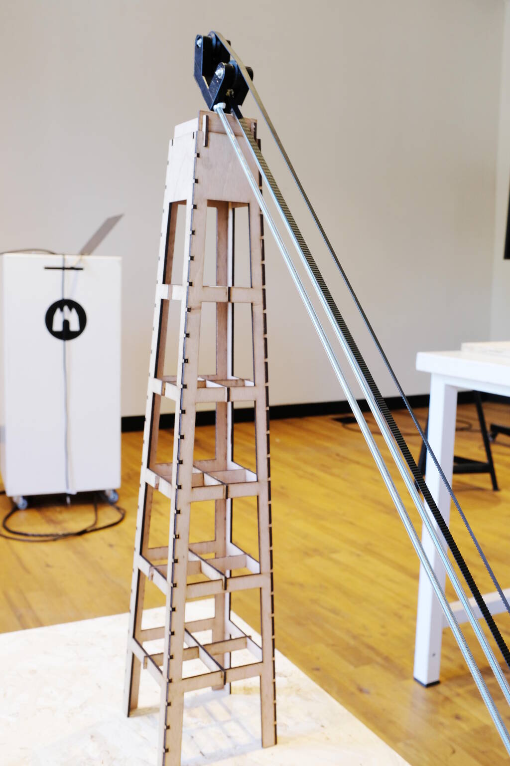
With all this work done, I can create a first setup. The two threaded M6 beams with wing nuts that can tension the belt resting on a pillar of 650 mm high:
A detail of the pillar's cross beams that increase the stability:
A track piece that will align with the belt:
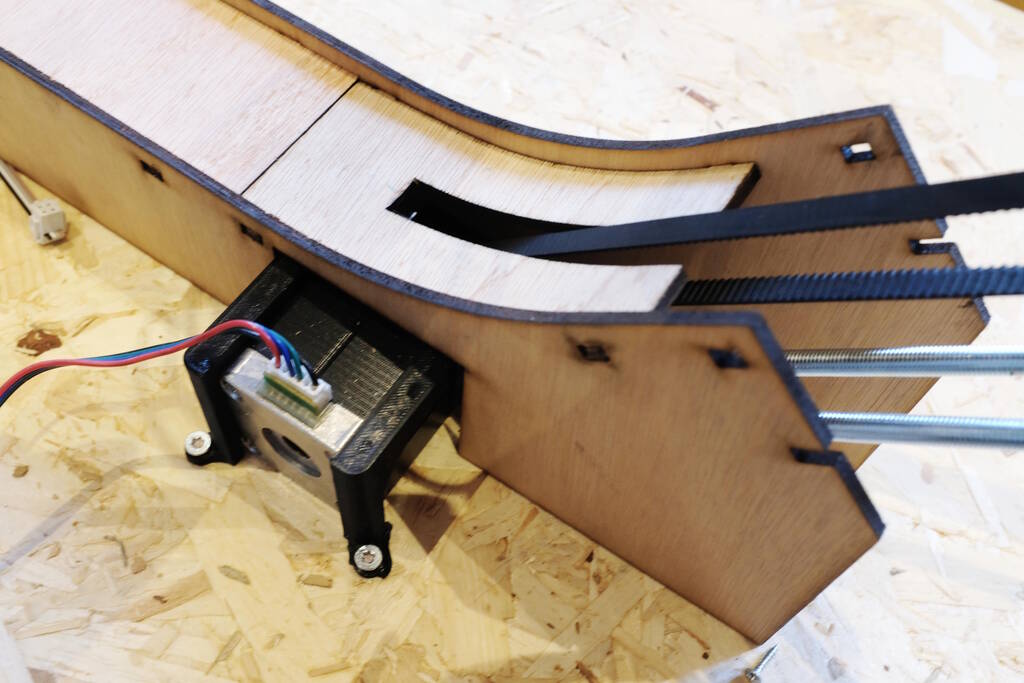
The track piece installed into the rest of the sytsem:
The track piece with the sensors:
One of the attempts to lift the car:
The car not tipping over the edge:
Redoing the CAD
I make use of the Assembly 4 workbench which works really well for me. It requires you to define local coordinate systems that can be matched to create an assembly. Unfortunately, the design with the curves makes it very difficult to use "origin-based design" in which you base features and connection between parts on as much fixed geometry as possible. Examples of fixed geometry are origins, axes, datum planes etc. However, because of the curves and the bends, it is sometimes really difficult to compute where to place the local coordinate systems.
The alternative is to place the local coordinate system at an edge. Because I couldn't apply this origin-based design anyway, I decided to simply go for edge-based positioning of local coordinate systems. However, because of FreeCAD's topological naming problems, the naming of the edges is highly unstable, breaking my assembly each time I make a small change.
This inflexibility was so frustrating that I decided to redo the CAD design two nights before my presentation and laser cut everything the next day. It became night work, but the design was much better, applying origin-based design where I could. This allowed me to change the trajectory of the belt with a new tensioner and to change the location of the track piece with the car sensors, giving me better results. The new tensioner with two pulleys:
The next day I laser cut the track pieces and could simply assemble the track.
Making the Exposition of the Project
On Thursday afternoon, I had everything assembled and tested, shooting videos for the final presentation. Sunke who manages the Waag location is a hero and provided me with a lovely bench on which I could place my project. I attached the motor brackets:
I rested the threaded beams with the belt and tensioner:
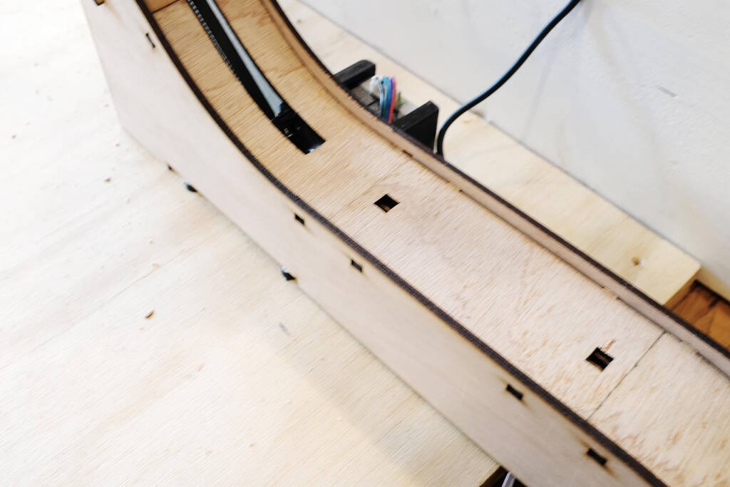
I built the track around it:
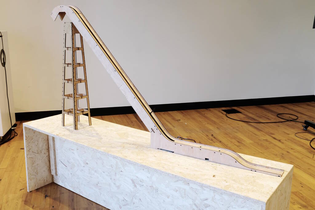
The structural components without the track of the lift:
The whole track on the bench:
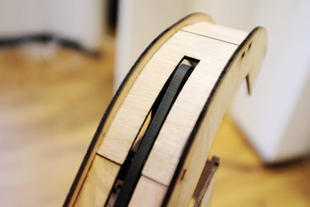
The flexures of the track:
The belt following the track:
Final Comments
Unfortunately, I didn't reach the goals that I set myself in the beginning; I only managed the first spiral and the car jumping became more like the car crashing down (which my son loves as well by the way). The main lesson is that if the CAD design turns out to be the limiting factor, then this is properly something limiting, especially if you depend so heavily on it as with this project.
Week 3 was the inspiration for this project. In Week 13 - Networking and Communications and Interface and Application Programming are related because I worked on the camera spiral in those weeks. Week 16 - Applications and Implications gives an overview, motivation, explanation of the spirals, related work, the components and systems, and the bill of materials of this project. Week 17 - Invention, Intellectual Property, and Income is relevant because it discusses dissemination and licensing. Finally, Week 18 - Project Development discusses the project plan, the tasks of this project, and reflects on the project.
Files
There are three licenses for the set of files in the archive file: CERN-OHL-S-2.0 for the CAD and electronics. GPL-3.0 or later for the source code except for the macros in FreeCAD that have been released under LGPL-3.0 or later, compatible with the licensing of FreeCAD.
Table of Contents
- Overview
- Switching Projects
- Experimentation Wood and Laser Cutting
- Pillars for the Track
- Modeling the Motor and Lift Mechanism
- Car Sensor Electronics
- 3D Printing
- Testing the Stepper Motor
- Lift Electronics
- Designing the Track
- Laser Cutting
- Integrate the Electronics
- First Build and Test
- Redoing the CAD
- Making the Exposition of the Project
- Final Comments
- Files