Week 11. Input Devices
Group Assignment
Here is our group assignment on Kelleigh's page:
Group AssignmentIndividual Assignment
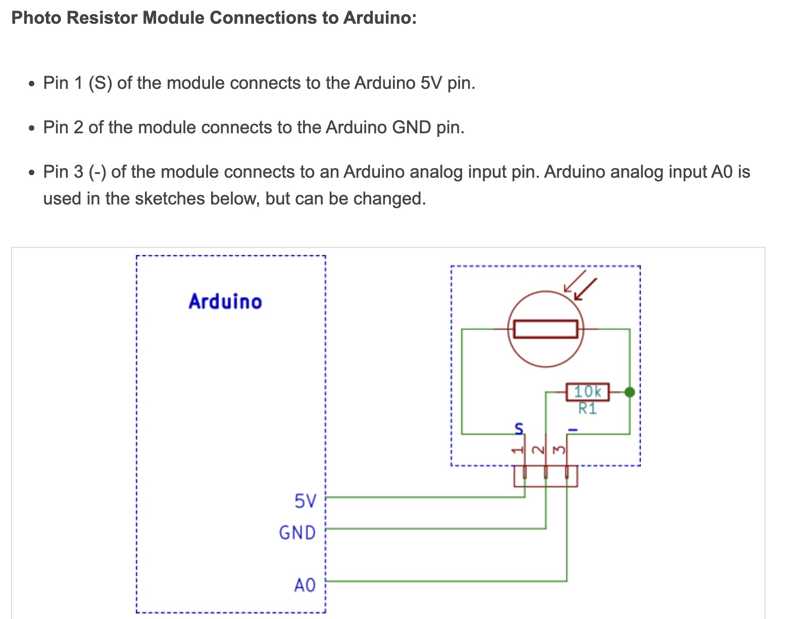
I chose to use a photoresistor. I chose this because at the time I was thinking about using this type of sensor in my final project so that the lights in the miniature home model I was creating would turn automatically at night.
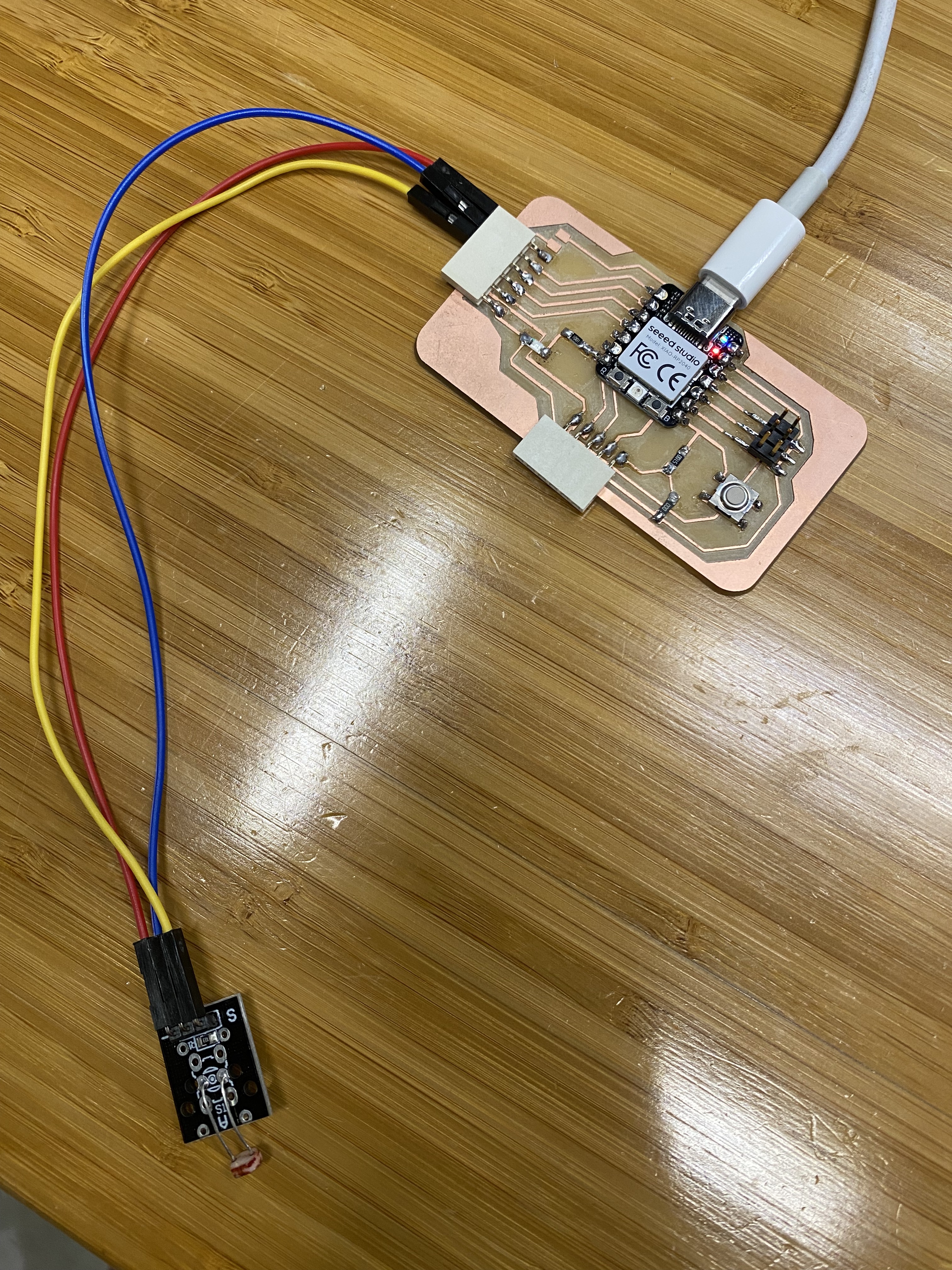
First, I had to ensure that everything was wired properly. It was difficult to follow the connections once all of my pieces were soldered in place, so I had to try several different combinations.

Then I connected my board to Arduino IDE. Here is my code:
      const int sensorPin = A0; // Sensor is connected to analog pin A0

void setup() {
  Serial.begin(9600); // Initialize serial communication
}

void loop() {
  int sensorValue = analogRead(sensorPin); // Read the sensor value
  Serial.println(sensorValue); // Print the value to the serial monitor
  delay(1000); // Wait for 1 second
}
At first, when I ran the code the serial monitor readings varied only slightly, from about 800 to 850. While I didn't know exactly what values to expect in light and dark conditions, it seemed like a very small variance. You can see it in the video below.
Again, it seemed off, and sure enough I had my blue and red wires reversed. I switched them around and now the values ranged from low 30s to 900s and varied appropriately based on the amount of light the sensor received. Here is a video of the sensor working: