Week 9: Output Devices

Week 9: Output Devices
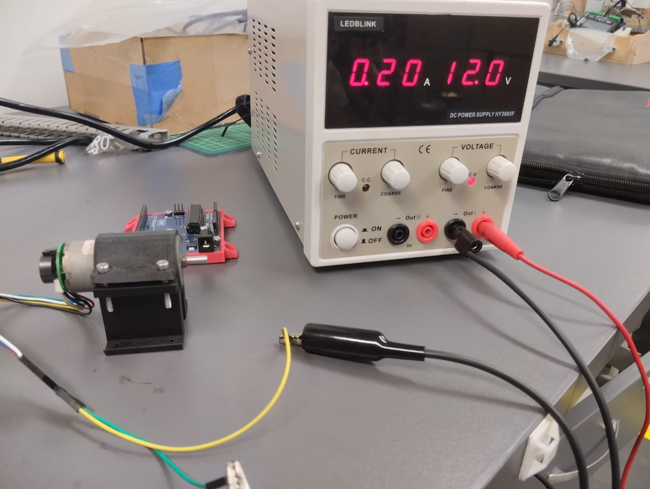
To measure the electrical consumption of the DC motor that I will use in my assignment, I only need to obtain its power, multiplying its working voltage by its current: 0.21A * 12.0 V gives us 2.52 Watts. Now assuming that the motor is running 2 hours a day, then 60 hours a month, we have that the consumption per month is: 0.00252 kW * 60 hours = 0.1512 kWh.

However, power supplies in a system usually do not have an interface that visually displays the consumption. For that, we use a multimeter. Voltage is measured in parallel, while current is measured in series.
Connection diagram for measuring current:

measurement video of current:
I powered my electronic board with 9V, and the multimeter displayed an average current of 0.15A. Multiplying these values, we obtain a power of 1.35 watts. Therefore, for 1 hour of consumption: 0.00135 kWh.
For this week I decided to use a DC motor, since I plan to use it in my final project. The motor I chose is the JGA-371 with an operating voltage range between 6 and 24V and a nominal voltage of 12V.

The new component that I will have to use is an SMD driver. In the laboratory we have 3 models of SMD drivers: A4953ELJTR-T, DRV8838DSGR and A4982SLPTR-T. Search for its specifications online to choose the right one.


At first I decided to choose the DRV8838DSGR, however, when I added its footprint library to Eagle I realized that the the size of the component was very small and it would cause me a lot of problems when soldering. So I decided on the A4953.
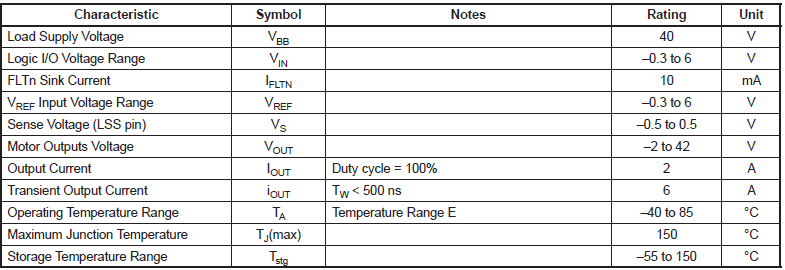
Here are the specifications of the driver:

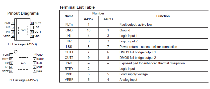
Here are the pin layout of the component:

The problem with the A4953 was that I couldn't find the schematic to download. Fortunately snapeda.com gives you the option to generate the schematic,here is a tutorial on how to do it easily

After following the steps you can download the library to use it in Eagle.
These are the components that were needed for the electronic board:


Then I proceeded to manufacture the board, following the steps that I documented during the electronic production week. After that i solder the board with its respective components, unfortunately, this time one of the components got tin stains on the underside, so I was forced to desolder it. I almost ruined the tracks, but finally managed to clean the tin and finish the board.

"Then it was time to test a program on the board, I followed the same procedure that I used during the electronic production week. I wrote a code that rotates the motor at its maximum speed for 3 seconds and then stops for another 3 seconds, For obtain it´s maximun speed either i use digitalWrite(PIN,HIGH) or analogWrite(PIN,255), PWM (Pulse Width Modulation) is a technique used to control the speed of an electric motor by varying the electrical signal sent to it. Instead of sending a constant signal, a pulsating electrical signal is sent, whose duty cycle (the time the signal is in a high state versus the time it is in a low state) varies according to the desired speed. This allows for precise control of the motor speed, as the amount of electrical energy it receives varies based on the duty cycle of the PWM signal.
code:
              int motorPin = 10; // PWM pin to control the motor
              int onTime = 3000; // duration in milliseconds of the motor on time (3 seconds)
              int offTime = 3000; // duration in milliseconds of the motor off time (3 seconds)

              void setup() {
                pinMode(motorPin, OUTPUT); // set the motor control pin as an output
              }

              void loop() {
                analogWrite(motorPin, 255); // turn on the motor at maximum speed (255 is the maximum value)
                delay(onTime); // wait for 3 seconds
                analogWrite(motorPin, 0); // stop the motor (PWM value of 0)
                delay(offTime); // wait for 3 seconds before restarting the cycle
              }