Week 8: Electronic Production
Week 8: Electronic Production
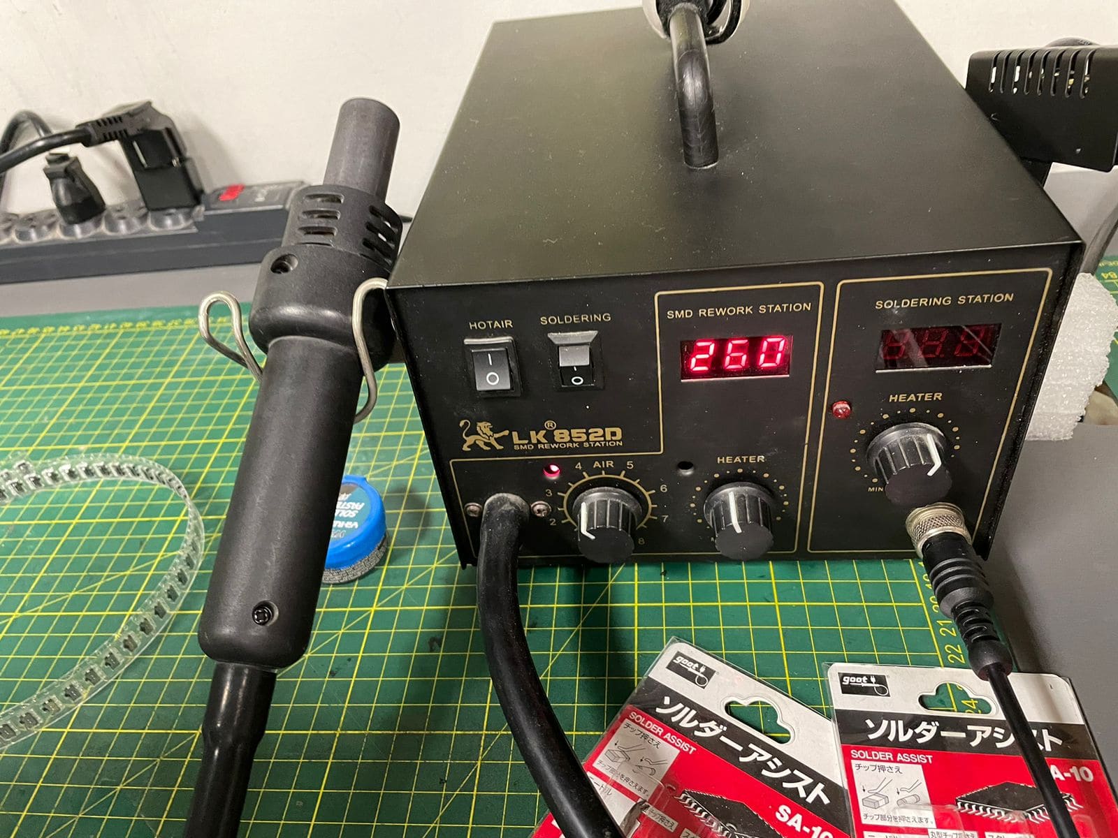
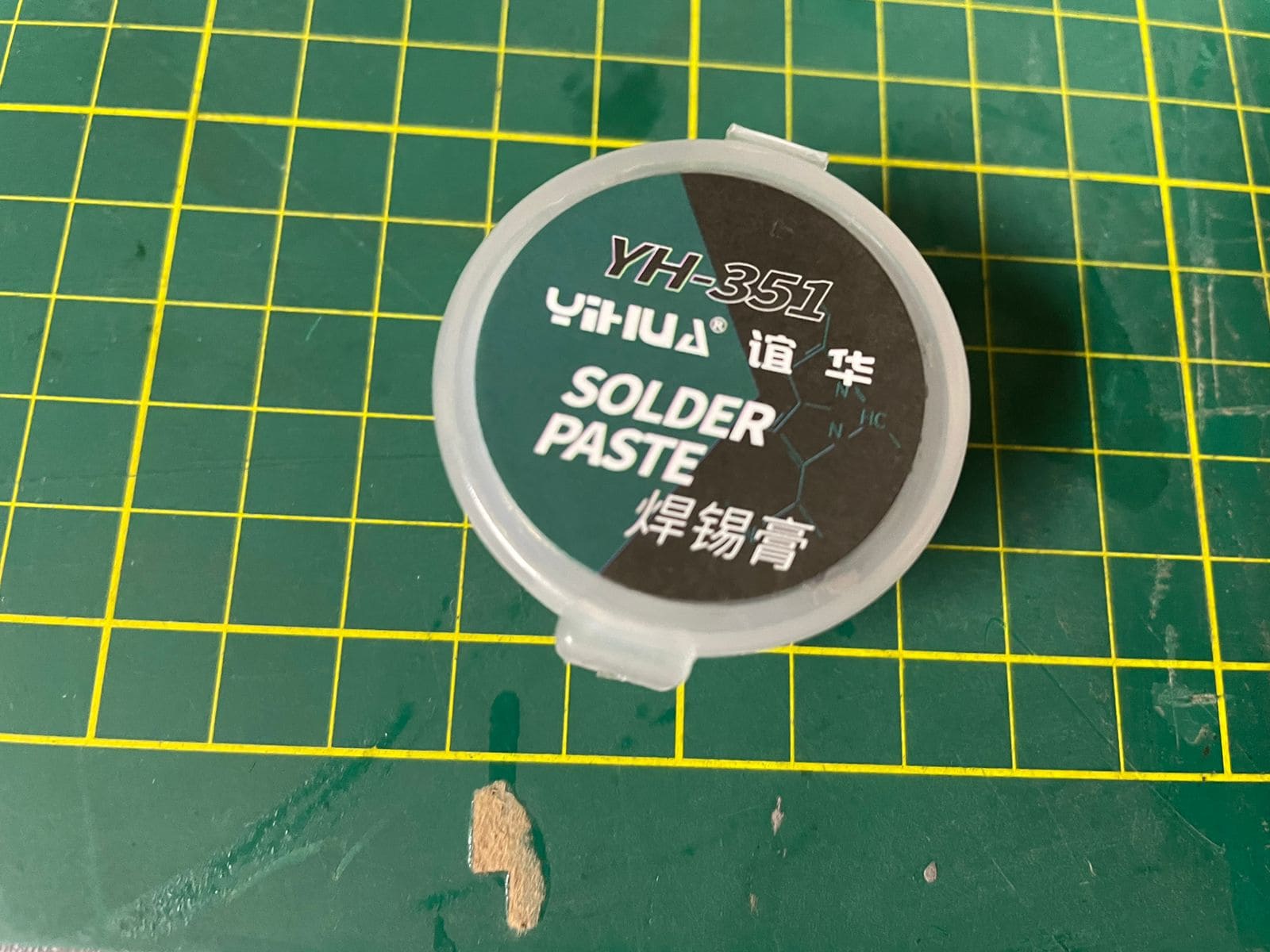
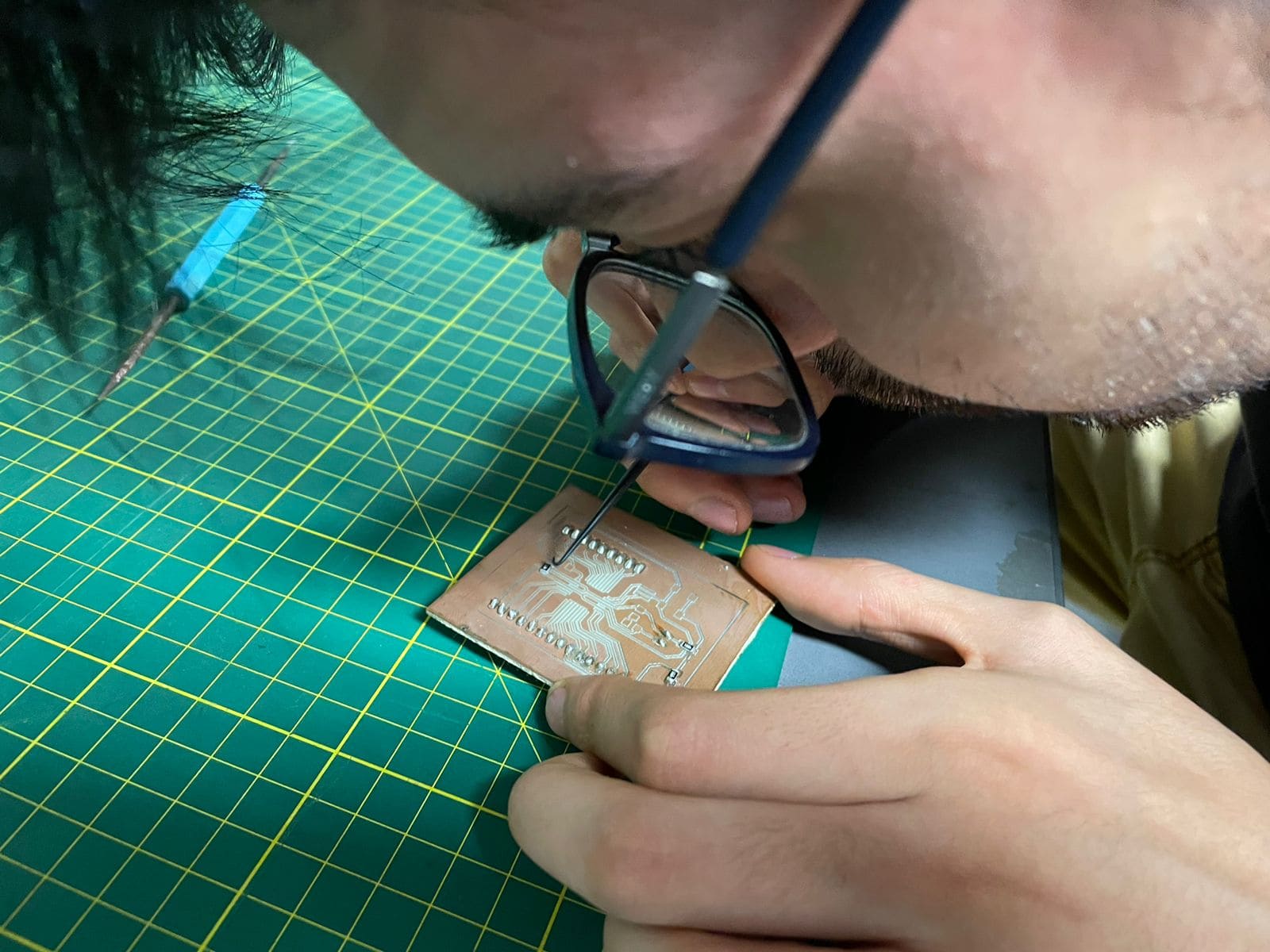
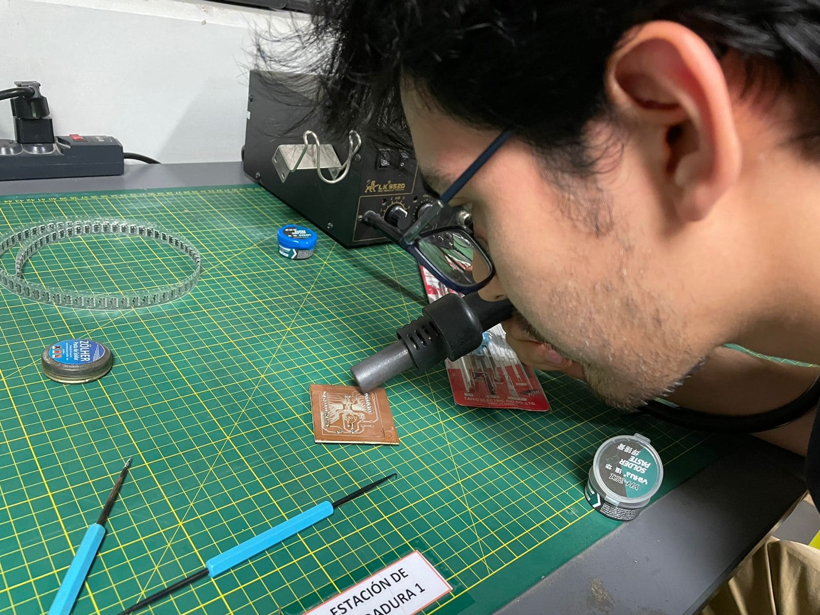
We started by practicing soldering of smd components on an old electronic board, we used solder paste and hot air, I also tried to use the soldering iron but it was very difficult and tedious, that does not mean that with the heat gun it was easy:
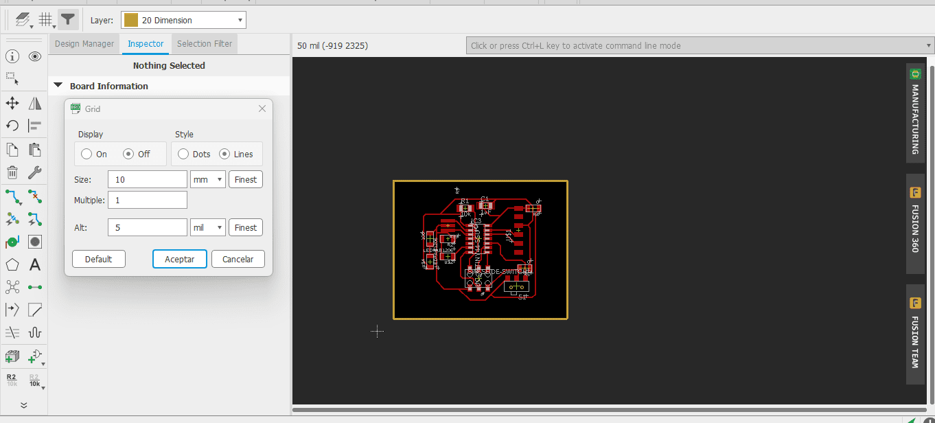
The soldering assistant tools were very helpful in spreading the paste on the copper and positioning the components. The lab has a Roland MDX540. This machine will be where we will produce our electronic boards. for the PCB traces we will use the 0.1 mm 45 V cutter , and to cut the edge of the plate we will use a 3mm flat cutter. To generate the G code we use the Fab mods platform, this is where the first problem arose when generating the code:
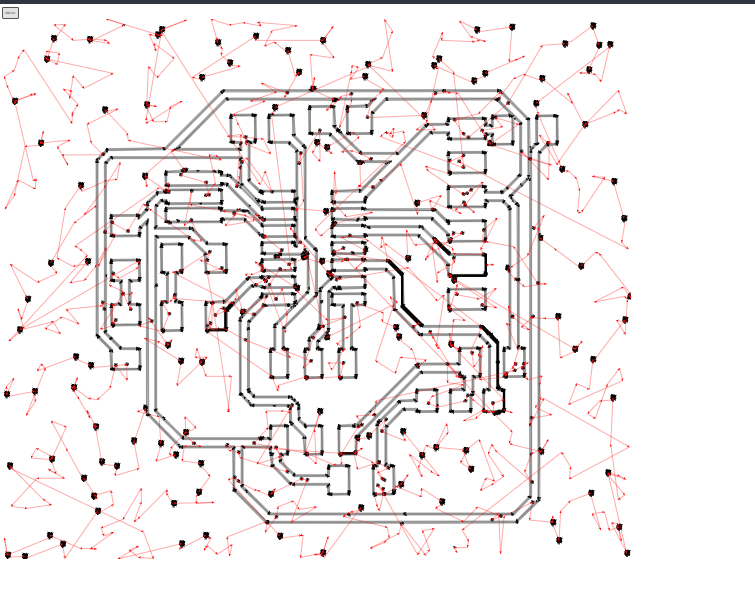
When calculating the traces, the program threw errors like the ones shown in the previous image, we tried different parameters thinking that these were the cause, but in the end we discovered that it was simply the browser we use, so we changed to chrome and the result was satisfying:
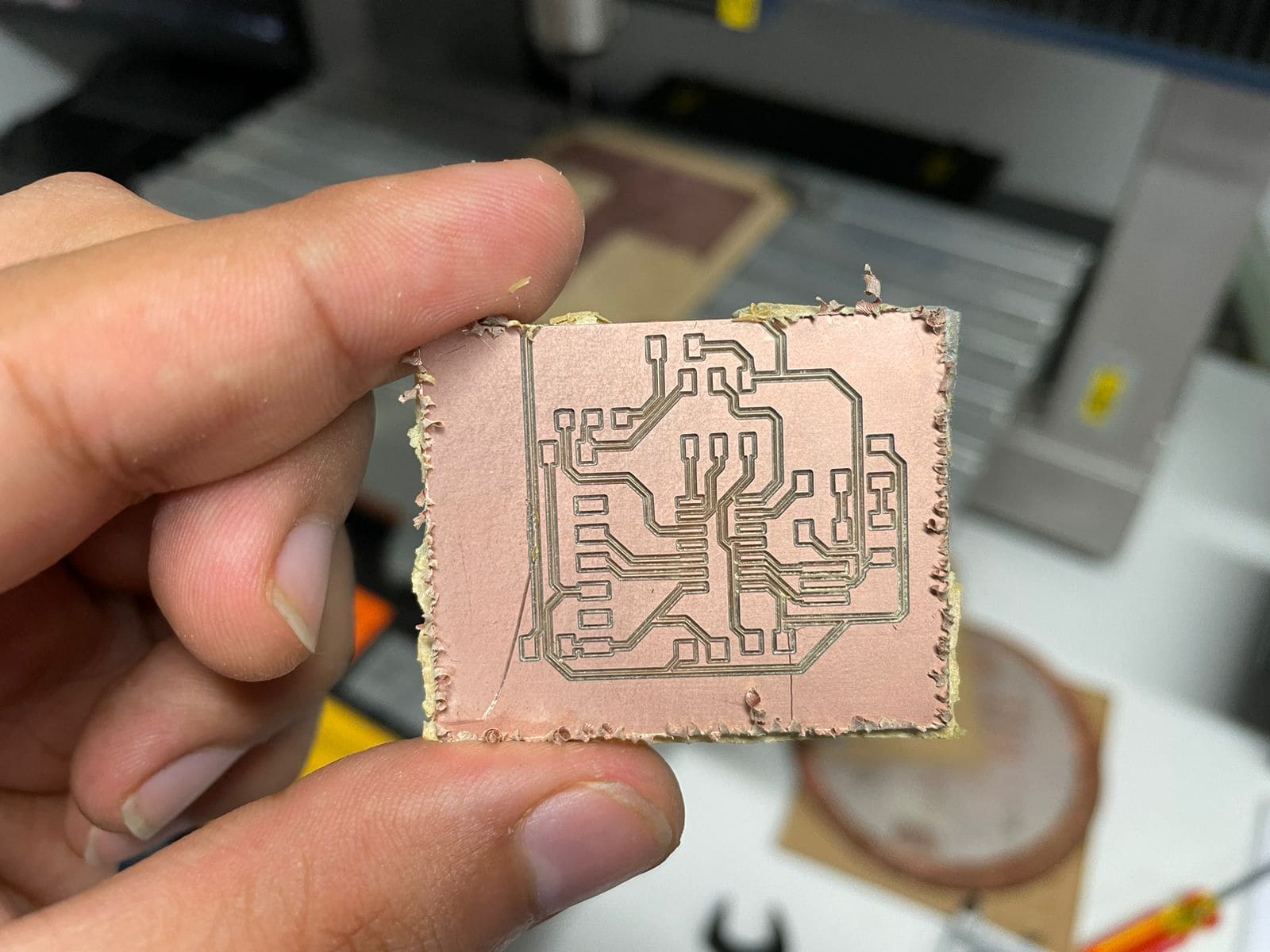
After some tests and some ruined boards we found the parameters good enough to proceed to manufacture our boards.
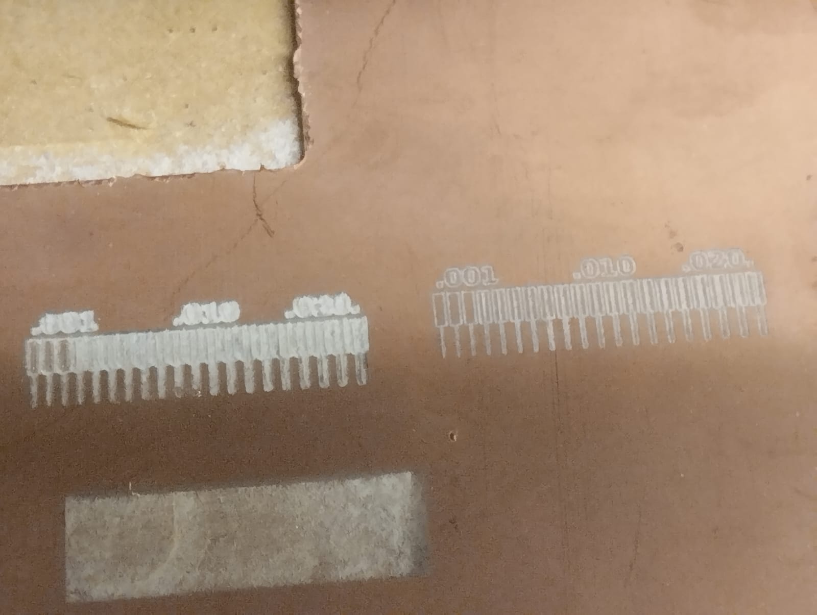
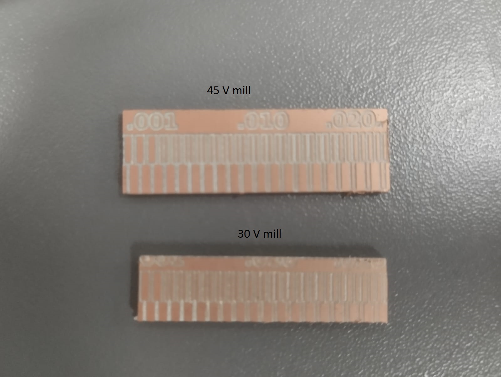
In the laboratory, I have 3 types of V-shaped milling cutters: 45, 30, and 60 degrees. I conducted tests with all three, and intuitively, the 30-degree cutter should work better, while the 60-degree cutter may eat away more copper and potentially ruin the tracks. The cutting depth will be 0.1mm as I found in various repositories. Here are the parameters I used for each cutter:
7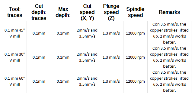
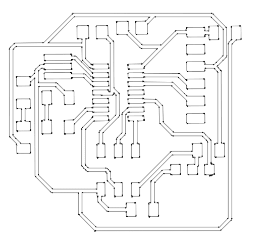
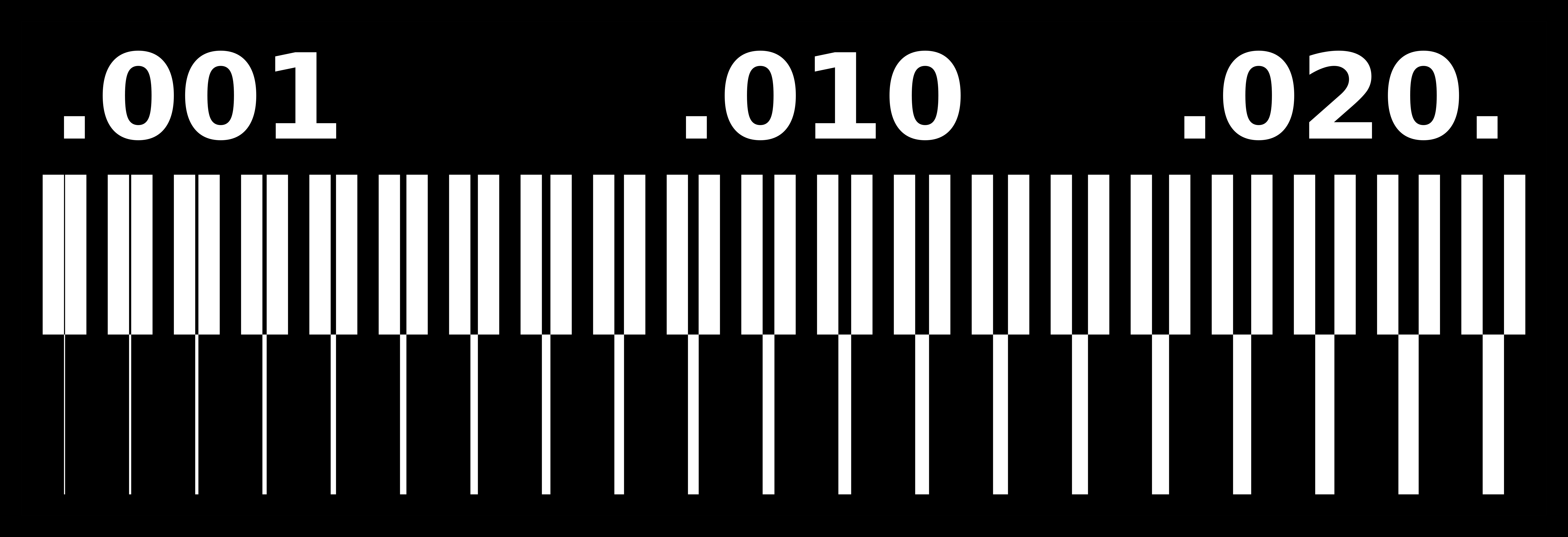
We are using the CAM trace width given by Neil as the reference file for comparison.
"There were several failures with the 60-degree milling cutter, and I also noticed that the CNC calibration sensor sometimes took longer to detect, causing the cutter to leave a hole and resulting in a much deeper cutting depth.
60-degree V mill:
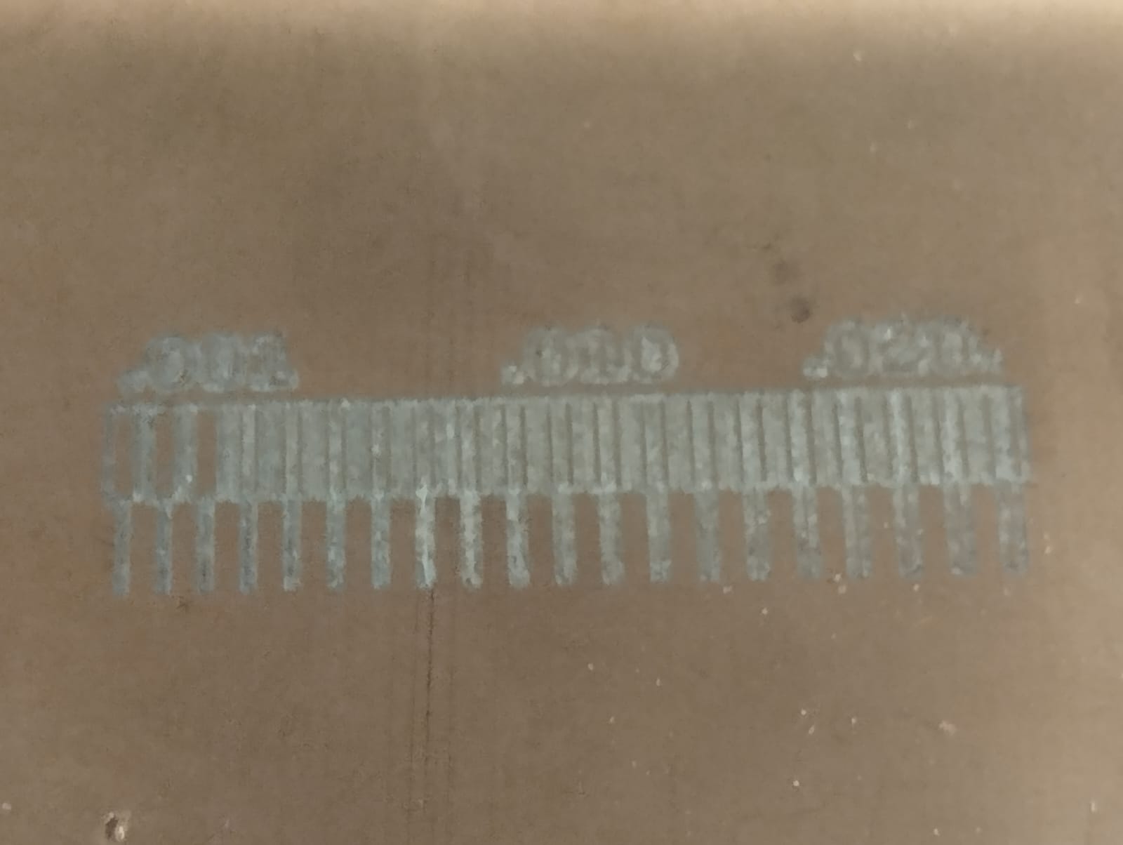
45 and 30 degree V mill:
In Electronic Design week, we designed an electronic board, however now we need to do 2 extra steps, add an exterior contour to the board so we can cut it out and convert it to an image so fab mods can generate the G-code. For this it is only necessary to export the image in PNG format. In conclusion, we must generate 2 images, one for the traces and another for the contour.
We add the border:
Do not forget that first you only need to show the layers that you need, in this case “TOP” for the traces.
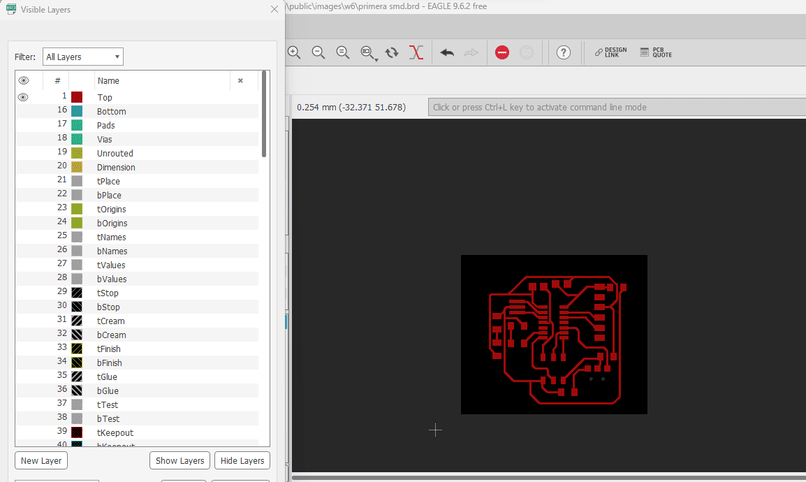
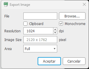
Then we export to png image " file > Export > image ", we place 1024 dpi resolution, activate the monochrome option and add the name and location.
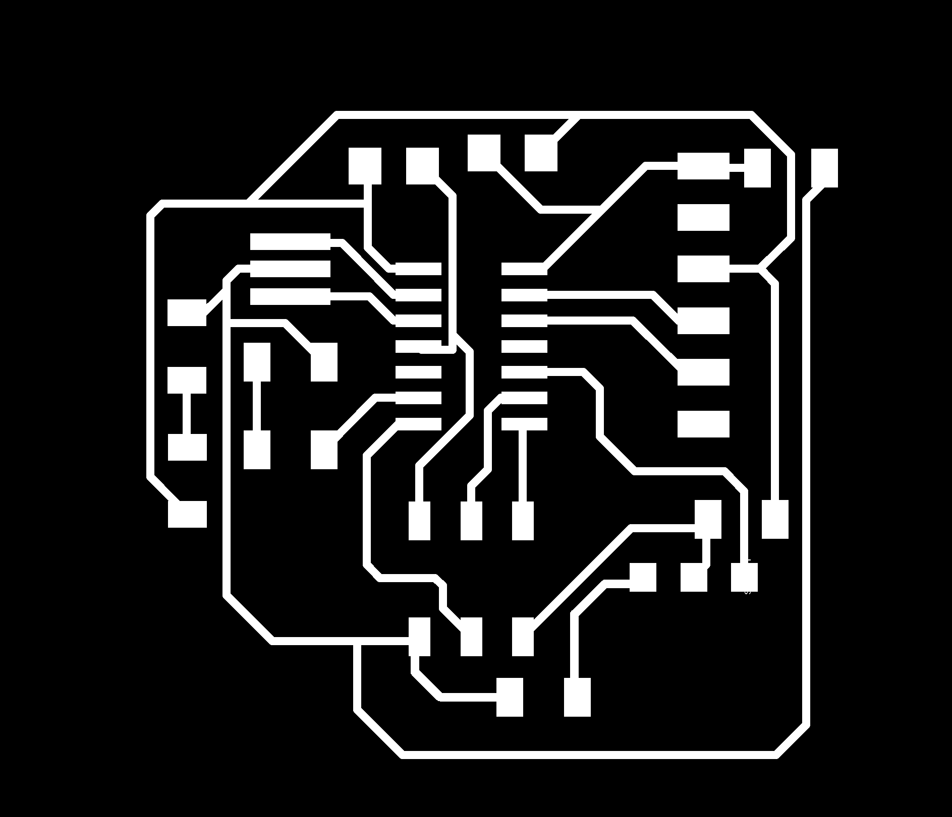
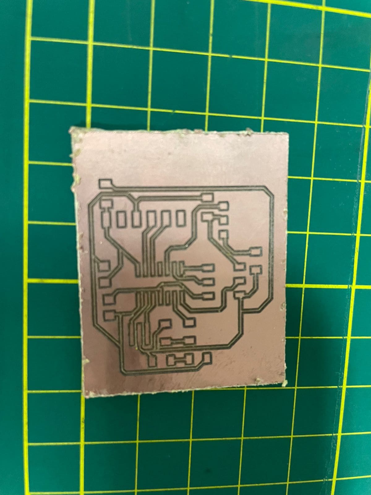
Result:
We carry out the same procedure for the layer where we draw the border:

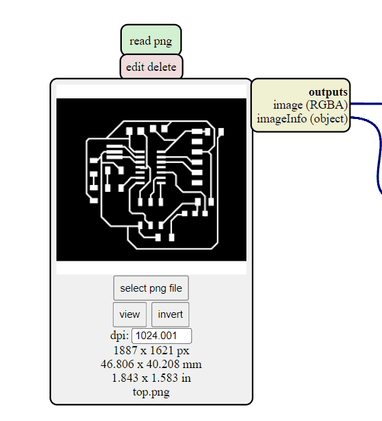
Once we have the images, we open the fab mods in the Chrome browser, the Brave gave us problems before, “programs > open server program > G code: mill 2D png”, then we add the image:
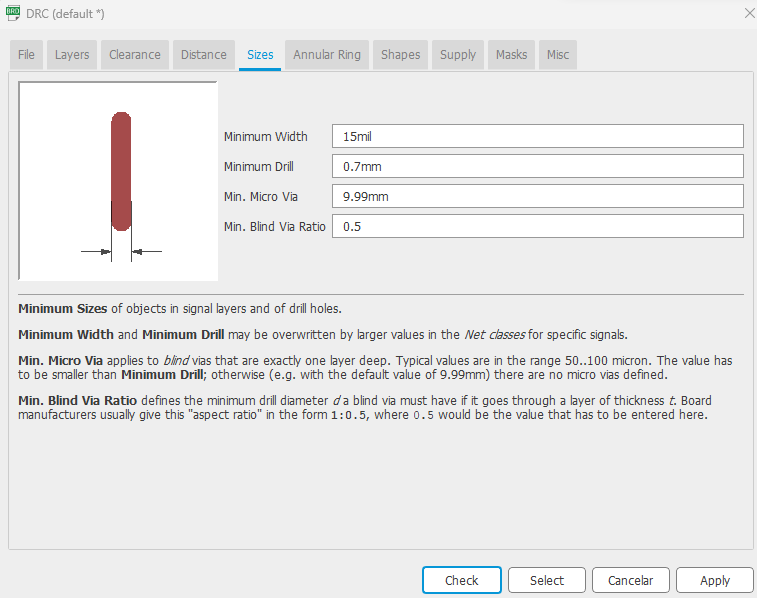
And we add the parameters:
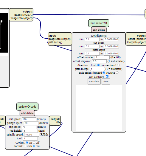
Finally, calculate is pressed and it generates the G code and a preview, the files are in the download section.
ncviewer.com in a G code web simulator, with this we can quickly simulate how our machine will act.
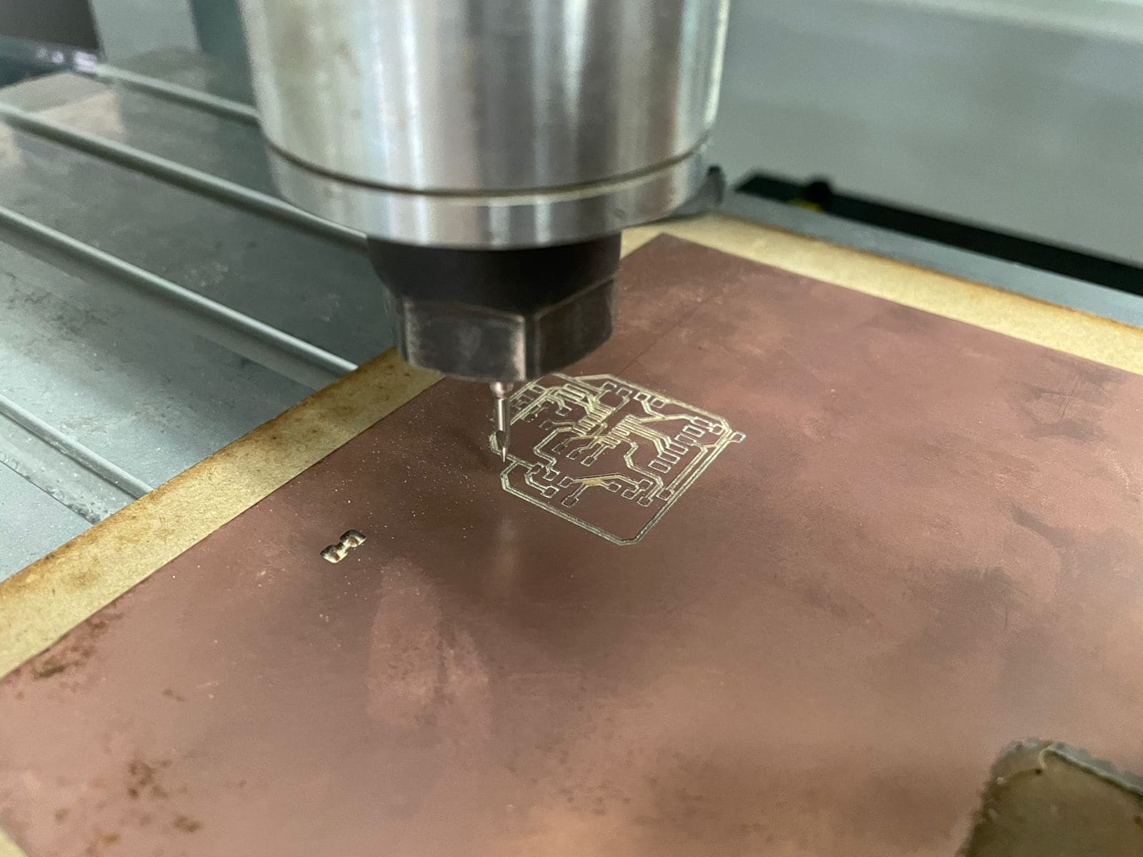
First, the copper and fiberglass board that we use as raw material is placed and fixed, then we place the appropriate cutter to carry out the work.
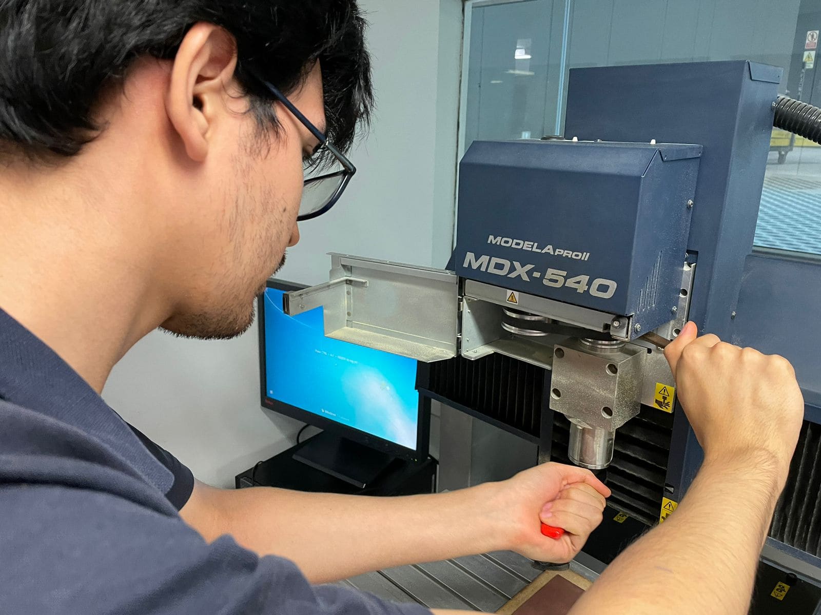
To set our X and Y axes of the Roland CNC we only have to use the machine control, pressing the button of the axis where we want to move, and once positioned in the coordinate that we want to be 0, we press "origin".
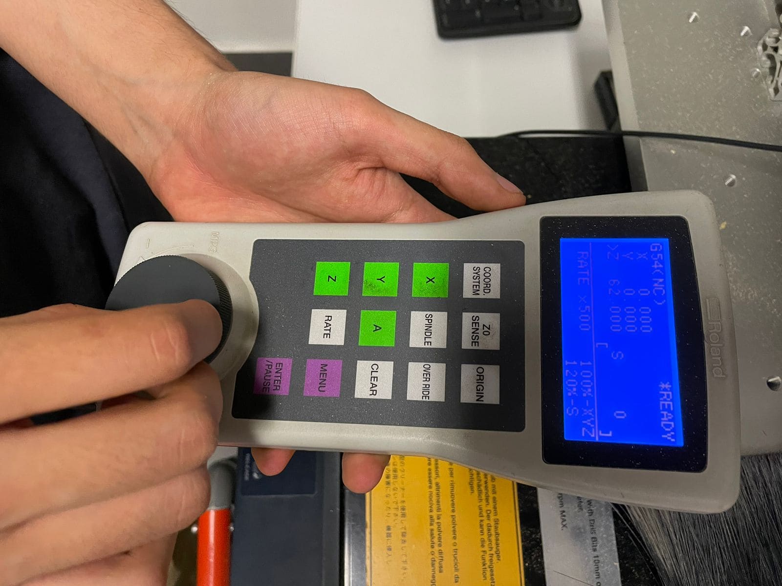
To set the Z axis we must add one more step. this time we will need a sensor as in the computer controlled-machining week, actually both machines work in a practically identical way. The Z axis is chosen, the sensor is positioned under the cutter and we press “Z0 sense”:
This is the software of the machine. The machine model is selected:
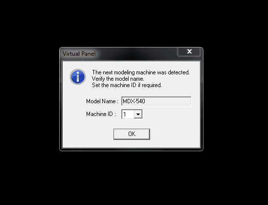
and we proceed to add the G code generated in the "cut" option.
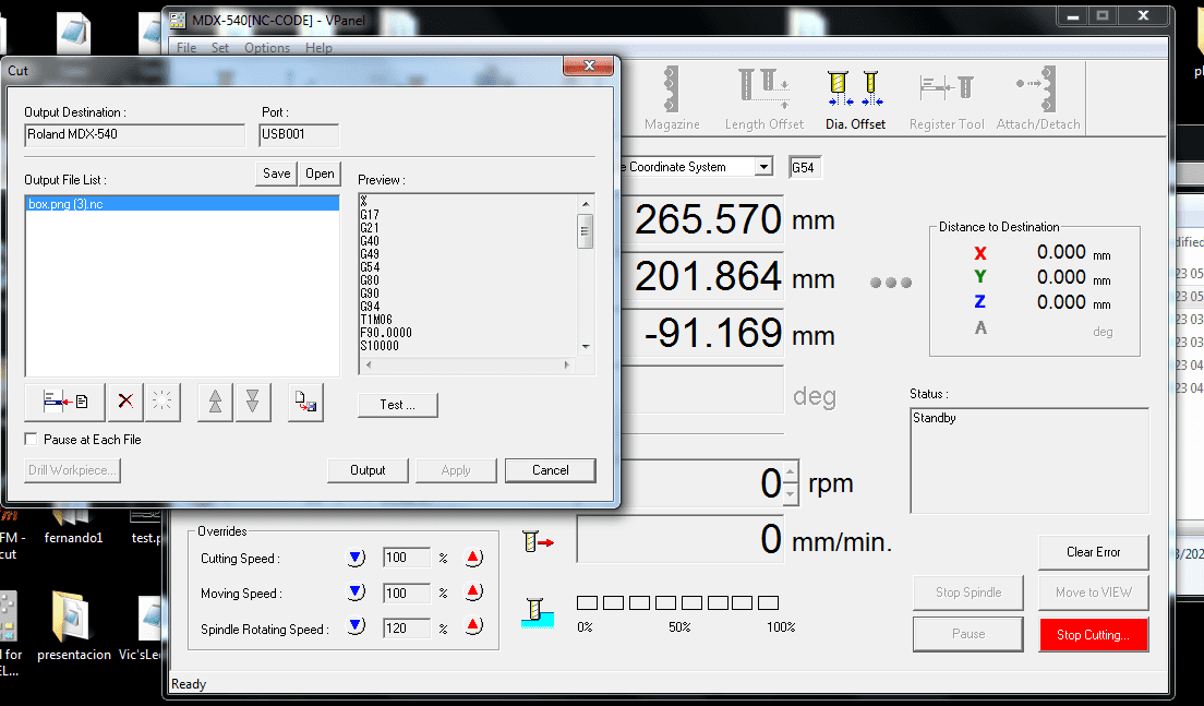
We press Output and the Roland will start working:
Once the strokes are finished, we must enter the border code, we change the tool for a 3 mm flat cutter to cut the border. For this it is necessary to recalibrate the Z axis.
The problems that arose during the process will be explained in the troubleshooting section.
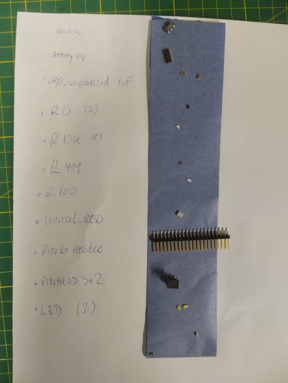
First it is advisable to list the components to be used and paste them on a sheet:
Guided by our eagle schematic we proceed to weld. This process is summarized in 4 steps:
Step 1: Place the solder paste where the component will be placed and position the component properly, this means that we check if the component has polarity as in the case of LEDS.
Step 2: Use the hot air gun to solidify the paste, it is recommended to aim at 45 degrees as seen in the figure:
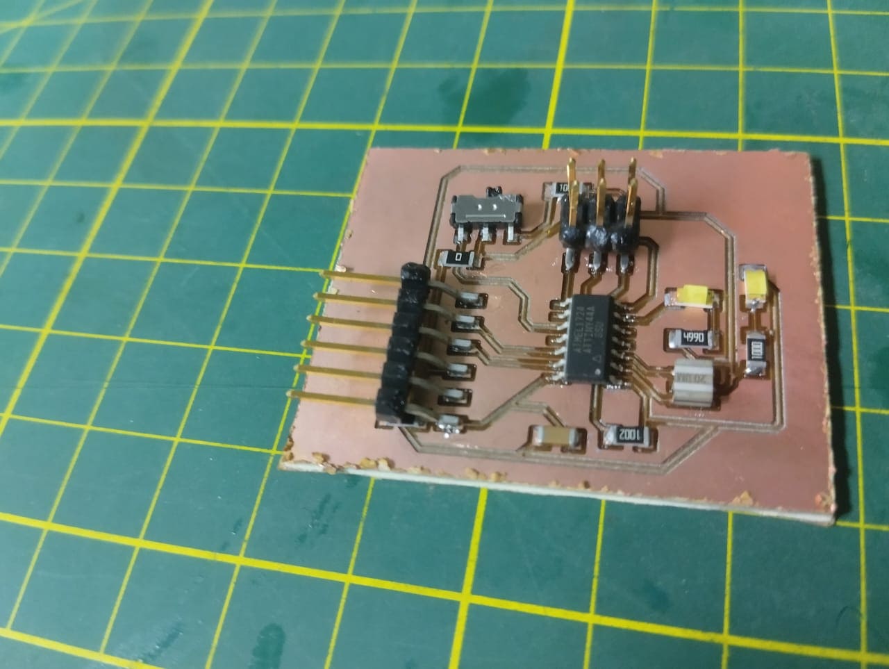
Step 3: Finally, it is visually inspected and continuity is measured to make sure that the soldering is good.
Finally we powered the electronic board, however, the LED did not light, indicating that there was a problem in the circuit.
There were 3 problems, the first was when generating the G code in fab mods, it was solved simply by changing the browser.
The second drawback was that the 3mm measurement of the cutter was not taken into account when drawing the border of the board, and this caused part of the circuit to break down:
A quick way to fix this was by calibrating the Y axis 3.24mm up:
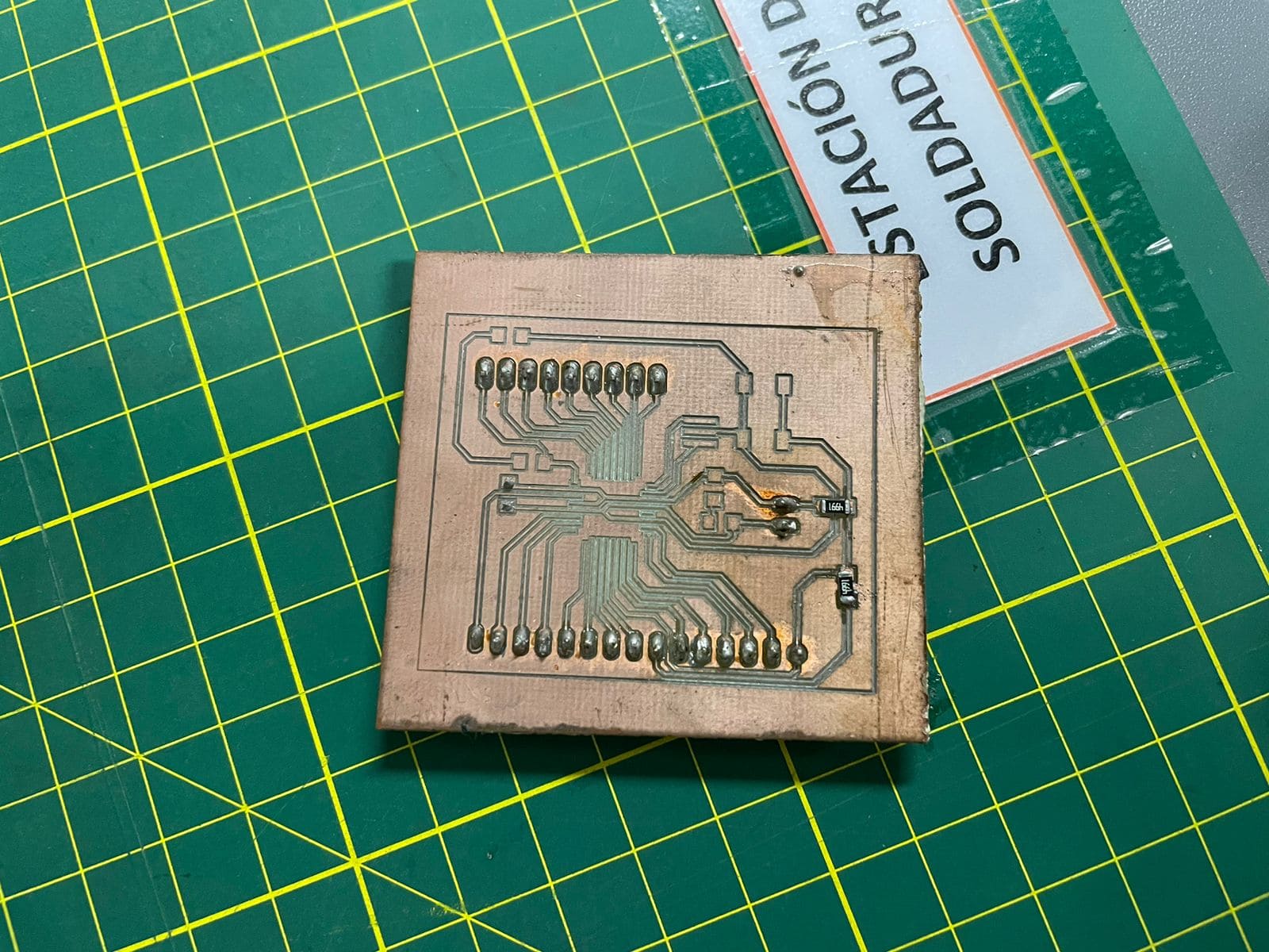
The third inconvenience we discovered after soldering the components, when powering the circuit, the led did not light up. With the help of the multimeter it was found that there was no continuity in a section of the gnd because the width of the line was very little.
Faced with this situation, we have two ways to solve it: increase the width of the line following the steps in the electronic Design week and make a new board:
Or a more practical way to fix the current board is to solder a wire that close he circuit and that´s what i did:
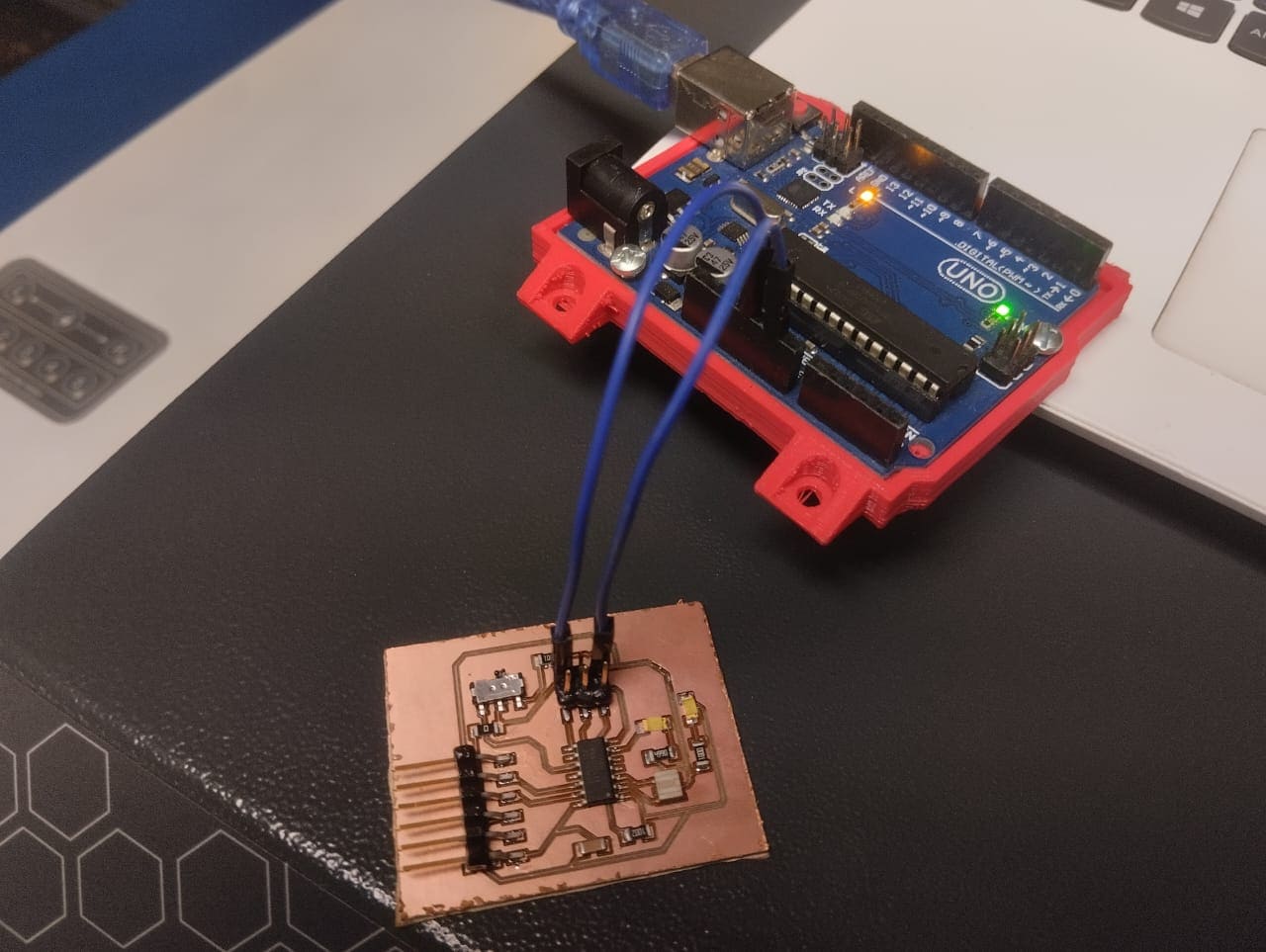
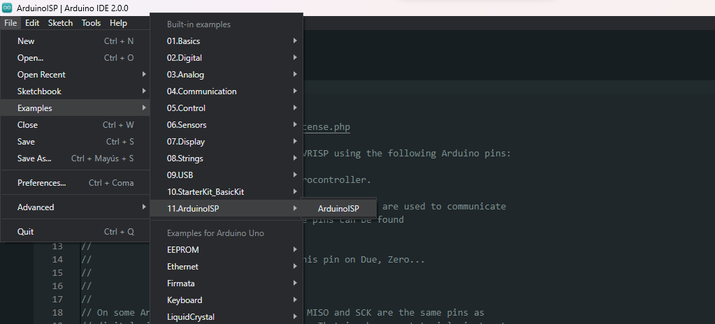
to program the Attiny44 I used the arduino as ISP, following the steps I found on this web page.
In short, the steps were:
Load the example "Arduino ISP"
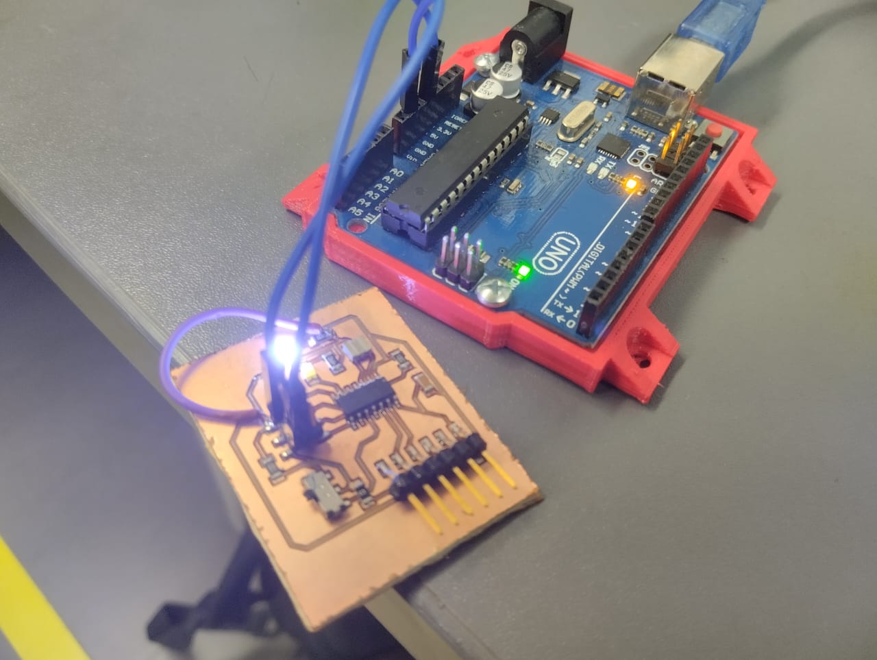
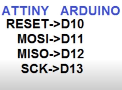
connect the arduino to the corresponding pins of our board and add a 10uF capacitor between the gnd and reset of the arduino:
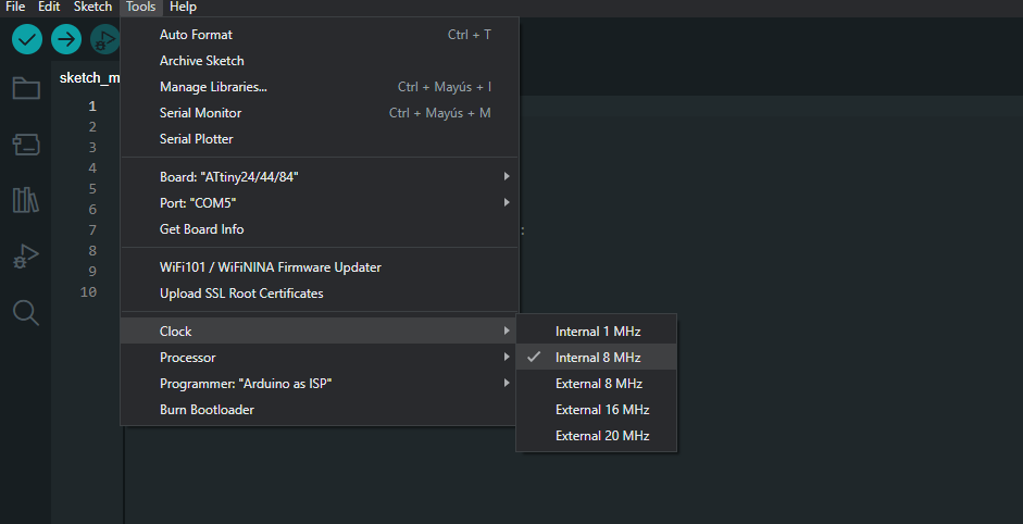
Add the library to be able to program the Attiny in the option "Additional boards manager URLs", configure, select parameters and burn bootloader:
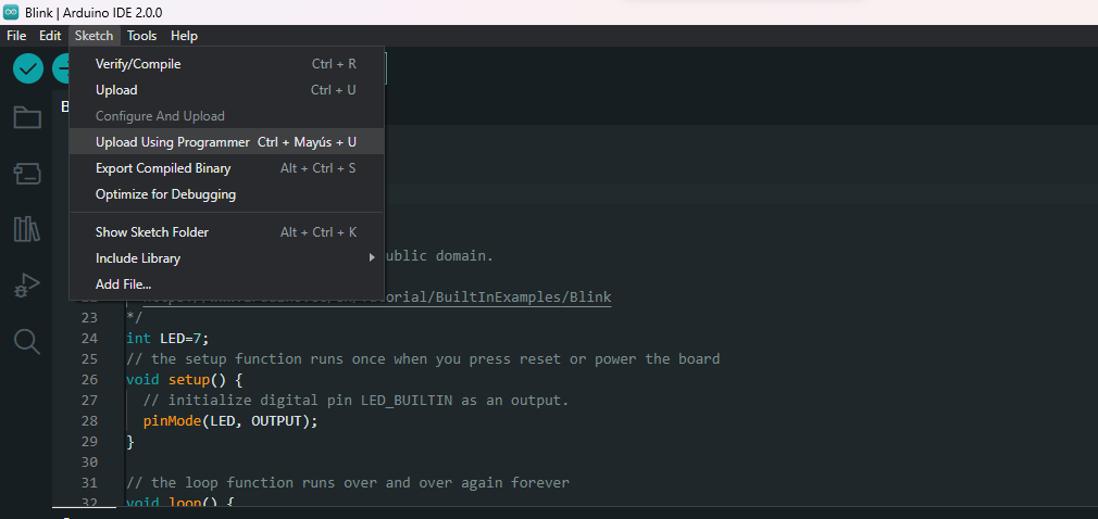
Once this is done, all that remains is to load the code that we want, this part is the only difference i found with the steps in the blog. To upload the code to the board we need to use the option "sketch > Upload using programmer":
Here is the classic "Blink" example:
.nc)
.nc)