Week 4: Embedded programming
Week 4: Embedded programming
For this week's group assignment I decided to pick 2 development boards : ESP32 and Rasberry pi pico
I waste some time trying to figure out why my computer does not recognize the PORT, the answer was that my PC required a USB to UART driver. Here you can find the link
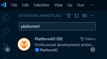
I decided to use "PlatformIO" in Visual Studio Code and thonny to program in micropython:
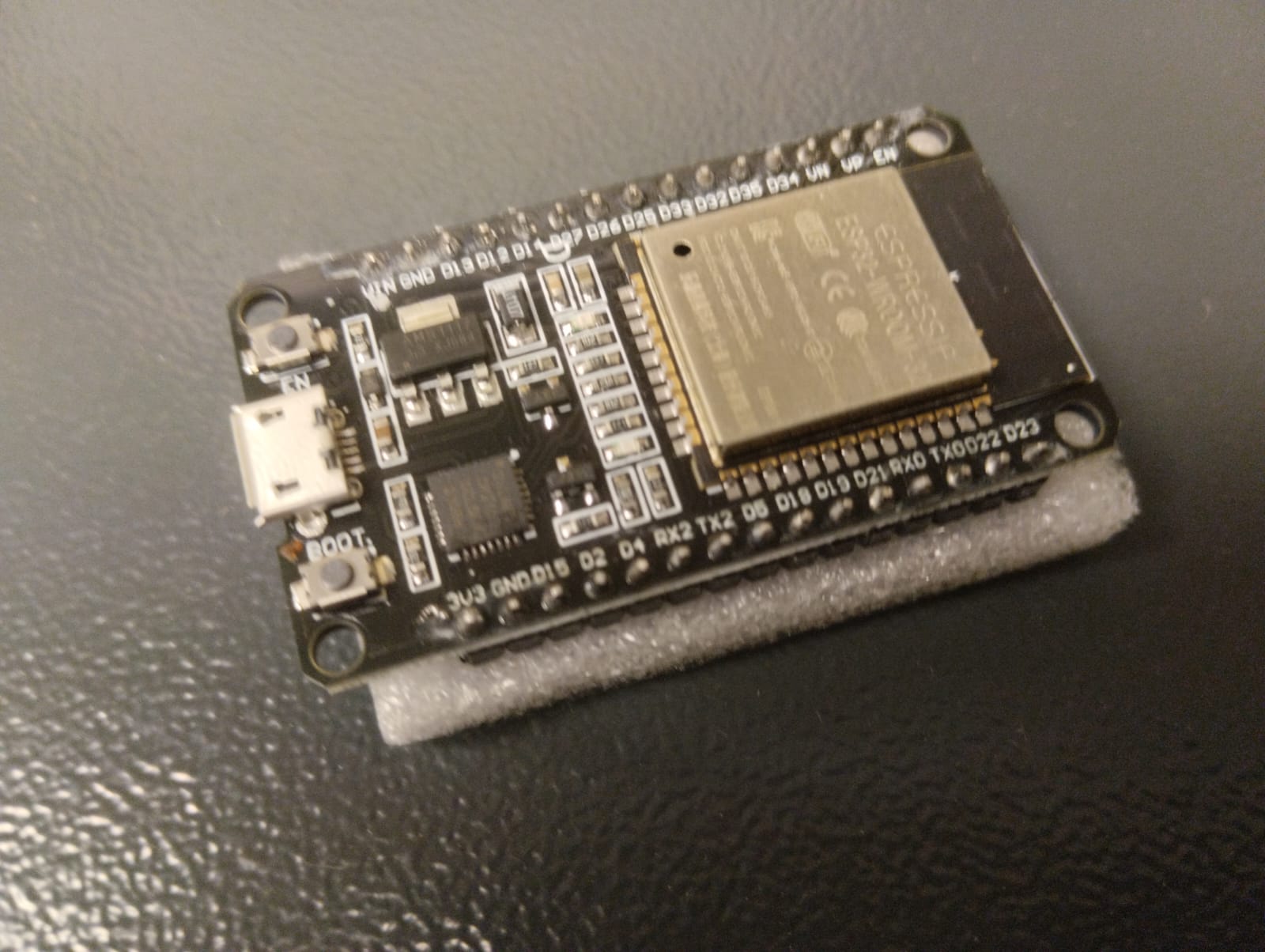
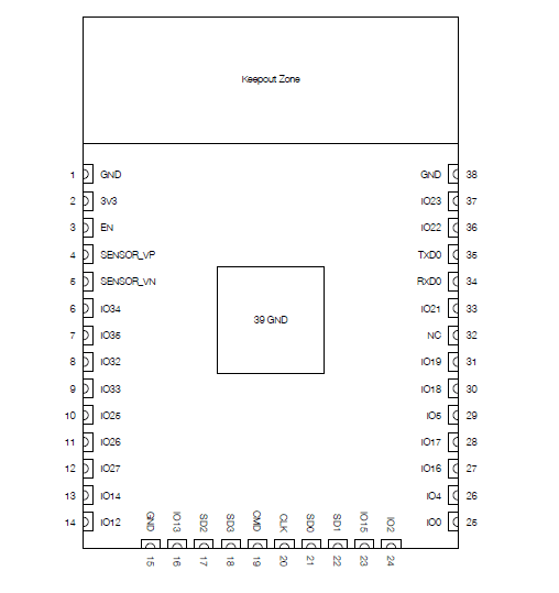
The ESP32 has a SOC (system on chip) "ESP32-D0WDQ6" that has a tensilica xtensa 32-bit-lx6 processor, with a speed of 240 MHZ and up to 34 programmable GPIOs
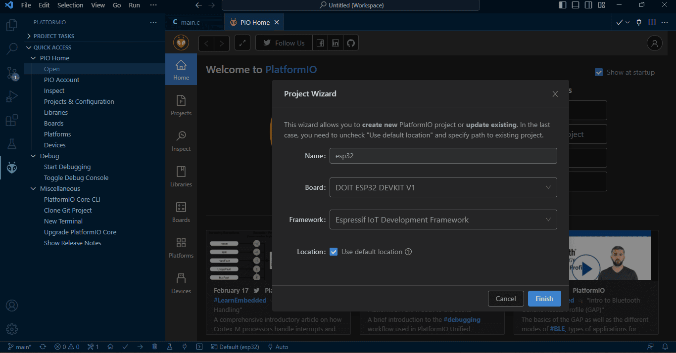
When you create a new project in PlatformIO you select the development board you use and the Firmware as seen below:
I Create a simple code that sets the GPIO 2 as an output for a LED and make it blink. Here is the code:
                            #include
                                #include "freertos/FreeRTOS.h" // LIBRARY FOR DELAYS
                                #include "freertos/task.h"
                                #include "driver/gpio.h"   // LIBRARY TO MANAGE PIN "GPIOS"


                                #define LED 2

                                void app_main()
                                 {
                                    gpio_set_direction(LED, GPIO_MODE_OUTPUT);

                                    while(1){

                                            gpio_set_level(LED,1);
                                            vTaskDelay(1000/ portTICK_PERIOD_MS);
                                            gpio_set_level(LED,0);
                                            vTaskDelay(1000/ portTICK_PERIOD_MS);
                                    }

                                 }
Micropython is a variant of Python that was created for microcontrollers. PlatformIO doesn't support micropython for programming, so I change to another IDE. To be able to program in micropython on the ESP32, it is first necessary to install the firmware of the version of micropython with which you want to work, I recommend the most up-to-date one. These versions are available at this link
There are different ways to install the firmware on the board, this link details the process for each of them:
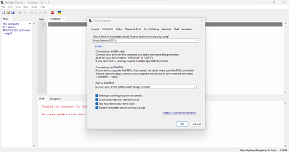
In my case I decided to use thonny, the advantage of thonny is that it also allows you to install Micropython firmware. To install the firmware we go to Run > Configure interpreter > Interpreter and select Micropython (ESP32) and the port (Remember that if the port its not detented, it is likely that you forgot to install the USB to UART driver).
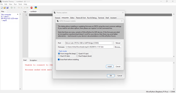
Then in the option "Install or update Micropython" we select the port and the firmware that we downloaded.
Once this is done we can start programming the esp32 in micropython. Create a simple code that receives as an INPUT a number from the keyboard and the LED blinks the number of times that you put.
                            from machine import Pin
                            import utime

                            led = Pin(2,Pin.OUT)
                            while True:
                                x=int(input("Enter number of blinks"))

                                for y in range(0, x):
                                    y+=1
                                    led.value(1)
                                    utime.sleep(1)
                                    led.value(0)
                                    utime.sleep(1)
                                    print(y)
                                y=0
I also tried to establish a WIFI communication and create a socket for it, create the server in the ESP32 with the code:
                            import network
                            import utime
                            import usocket

                            wf=network.WLAN(network.STA_IF)
                            wf.active(True)

                            # print(wf.scan())
                            l =wf.scan()
                            for k in l:
                                print(k)

                            wf.connect("Wifi101","samuelito2000")
                            while not wf.isconnected():
                                print(".")
                                utime.sleep(1)
                            print("ya estoy conectado")
                            print(wf.ifconfig())

                            s=usocket.socket()
                            s.bind(("192.168.1.8",2025))
                            s.listen(10)
                            print("esperando cliente")

                            while True:
                                (sc,addr)=s.accept()
                                print(addr)
                                continuar2=True
                                while continuar2:
                                    mensaje = sc.recv(64)
                                    if not mensaje:
                                        continuar2=False
                                    else:
                                        print(mensaje.decode())
                                sc.close()
                            s.close()
                            print("End")
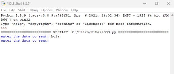
And then create the client in the Python IDLE:
                        import socket
                        s = socket.socket()
                        s.connect(("192.168.1.8",2025))
                        continuar = True
                        while continuar:
                            a = input("enter the data to sent: ")
                            if a == "END":
                                continuar=False
                            else:
                                s.send(a.encode())
                        s.close()
                        print("Program END")
The program consists of sending bit-type messages that will be encoded by the client and decoded by the server adding “.encode()” and “.decode()” after the message
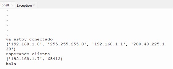
here is the reception of the message
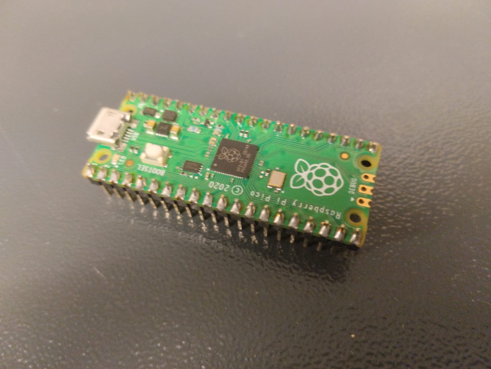
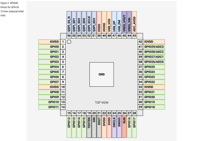
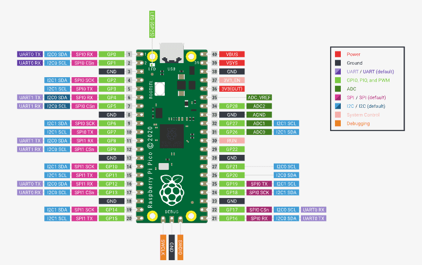
This development board has an RP2040 microcontroller from the ARM Cortex-M0+ family, its datasshet can be read here . This MCU has 30 GPIO; however, the board only uses 26. The 2 MB flash memory is external, that is, it is not included in the MCU and has a speed of 133 MHz Below you can see the pin configuration of both the microcontroller and the board.
I programmed in micropython following the same steps as the esp32. The following program reads the status of the button on Pin GP12 and through a conditional statement activates Pin GP3 as a digital output.
                            from machine import Pin
                            import utime
                            led = Pin(3,Pin.OUT)
                            button = Pin(12,Pin.IN)
                            while True:
                                bt=button.value()
                                utime.sleep(0.3)
                                if bt == 1:
                                    led.value(1)
                                else:
                                    led.value(0)
In conclusion, the datasheet provides detailed information about the pinout and configuration of the microcontroller. It specifies the functions of each pin, such as GPIO (General Purpose Input/Output), power supply, communication interfaces (UART, SPI, I2C), and interrupts. This information is crucial for connecting external components and peripherals to the microcontroller and configuring the appropriate settings in my code.
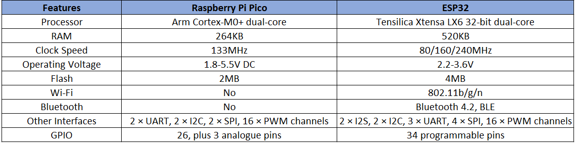
Here is a table of the key features of each board:
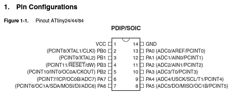
The datasheet for the attiny44 can be accessed through this linkhere. From the information I gathered, it appears that this microcontroller is equipped with an internal oscillator operating at 8MHz. However, it can be connected to an external electronic board if desired. In total, it has 14 pins, with pin 1 designated as VCC and pin 14 as GND. There are 5 digital inputs and 2 analog inputs available. For ISP communication and bootloader booting, pins 4, 7, 8, and 9 (Reset, MOSI, MISO, and SCK, respectively) are typically utilized. Additionally, pins PB2, PA7, PA6 and PA5 can be utilized for PWM.
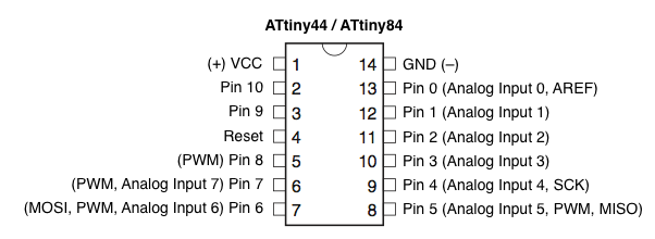
Here is an image that shows the number of the PIN to code in arduino.
To program the Attiny44 I used Arduino IDE and the arduino as ISP, following the steps I found on this web page.
Steps:
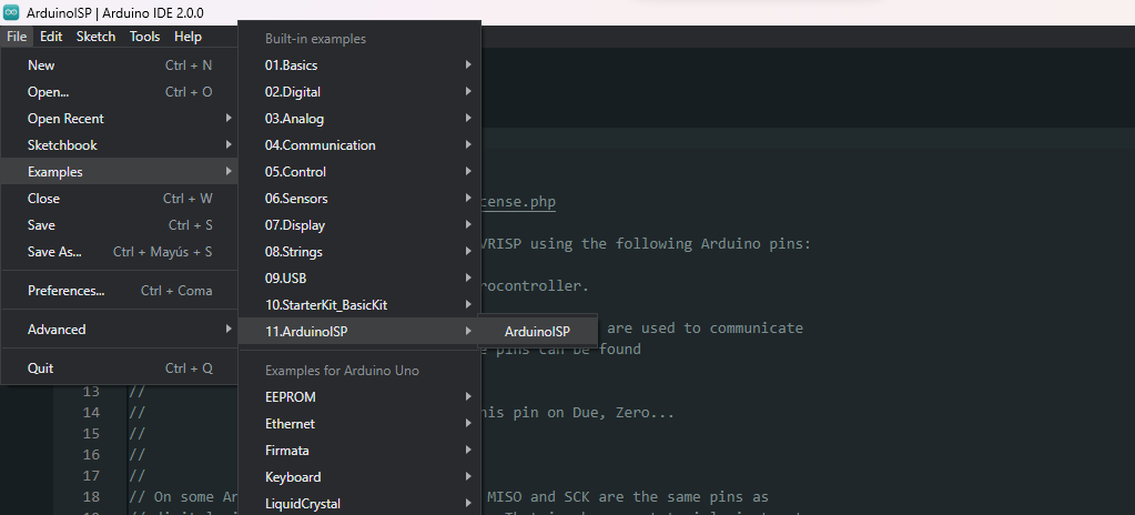
Load the example "Arduino ISP"
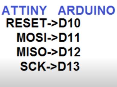
connect the arduino to the corresponding pins of our board and add a 10uF capacitor between the gnd and reset of the arduino:
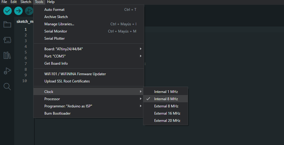
Add the library to be able to program the Attiny in the option "Additional boards manager URLs", configure, select parameters and burn bootloader:
Once this is done, all that remains is to load the code that we want, this part is the only difference i found with the steps in the blog. To upload the code to the board we need to use the option "sketch > Upload using programmer":
I used the board i made in input devices week.
Here is the code:
                        #include
                            SoftwareSerial monserial(0, 1);//rx and tx
                            int LDR = 2;//PA2
                            int LED = 7;//PA7
                            void setup() {

                              pinMode(LED, OUTPUT);
                              pinMode(LDR,INPUT);
                              monserial.begin(9600);
                            }

                            // the loop function runs over and over again forever
                            void loop() {
                              int va=analogRead(LDR);//reading analog value
                              monserial.println(va);
                              digitalWrite(LED, HIGH);   // turn the LED on (HIGH is the voltage level)
                              delay(350);                       // wait for a second
                              digitalWrite(LED, LOW);    // turn the LED off by making the voltage LOW
                              delay(350);                       // wait for a second
                            }
This code reads an analog signal from an LDR connected to pin "PA2" and displays it on the serial monitor using a USB to UART cable: GND,VCC,TX,RX.
video: