Week 12: Input devices
Week 12: Input devices
Input devices are hardware components that allow users to interact with a computer or other electronic devices. These devices are used to input data, commands, and instructions into the computer system. Some common examples of input devices include keyboards, mice, touchpads, joysticks, scanners, microphones, and cameras. Each input device has its own unique method of inputting data into the computer. For example, a keyboard uses physical keys to input letters, numbers, and symbols, while a mouse uses a combination of buttons and movement to input commands and manipulate objects on the screen.
I used an oscilloscope to test and analyze the analog and digital signals of two different input devices: a Light Dependent Resistor (LDR) analog sensor and an infrared digital sensor.
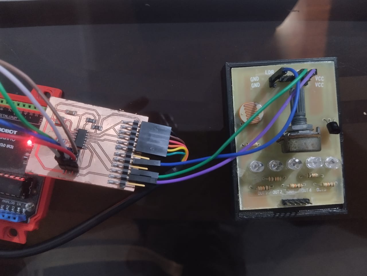
We began by connecting the LDR sensor to the oscilloscope using the appropriate cables. We adjusted the oscilloscope to measure the analog signal coming from the LDR. This allowed us to observe the changes in the sensor's resistance based on the amount of light incident on it. With the oscilloscope, we were able to visualize and analyze the resulting voltage, providing us with real-time information on the variation
Values displayed:
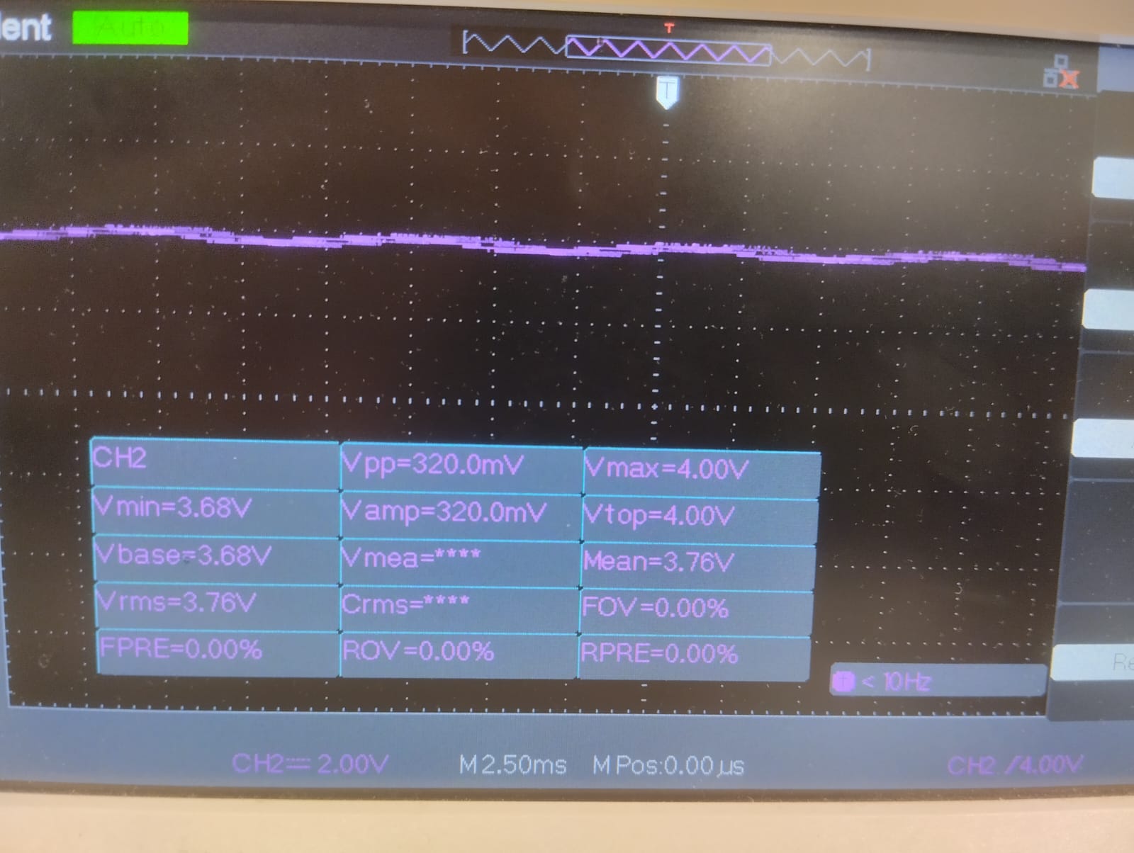
We can see real-time data of the voltage, such as maximum voltage, minimum voltage, mean voltage, etc.
The next video shows the digital signal of the infrared sensor, typically represented as a series of discrete voltage levels. It changes between two values: 0 and 1, or HIGH and LOW. In the video, we can see on the display that when the transmission between the emitter and receiver is blocked, the voltage reads 3.82V, and when it's not blocked, it shows approximately 0V.
To summarize, analog signals offer a vast range of voltage values within their scope, enabling them to accurately represent the signal. Conversely, digital signals possess distinct voltage levels, which imposes limitations on the precision of signal representation. Furthermore, analog signals are susceptible to interference and distortion, which can alter the waveform's shape and magnitude. Such noise and distortion can be observed as fluctuations or variations in the waveform when viewed on an oscilloscope. In contrast, digital signals are more resistant to noise and distortion due to their reliance on discrete voltage levels.
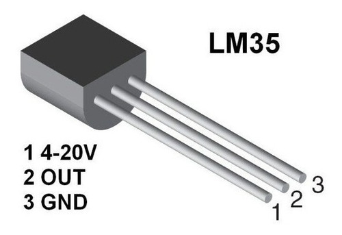
For this week, I decided to use a button and an LM35 as input devices. A button is a simple device used as input in electronics and programming. When the button is pressed, an electrical circuit is closed, allowing electric current to flow and sending a signal to the Attiny44 that I will be using. Meanwhile, the LM35 is an analog temperature sensor that provides a voltage output proportional to temperature. It is easy to use and can be powered with a voltage source between 4 and 30 volts. Its accuracy of ±0.5°C makes it ideal for projects that require precise temperature measurements, such as temperature control systems, thermostats, and environmental monitoring. In addition, its TO-92 format allows for integration into projects with limited space.
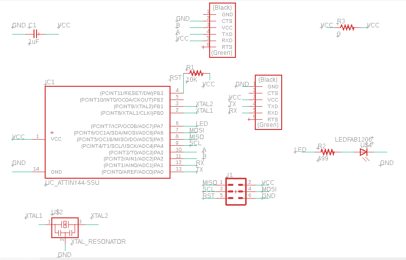
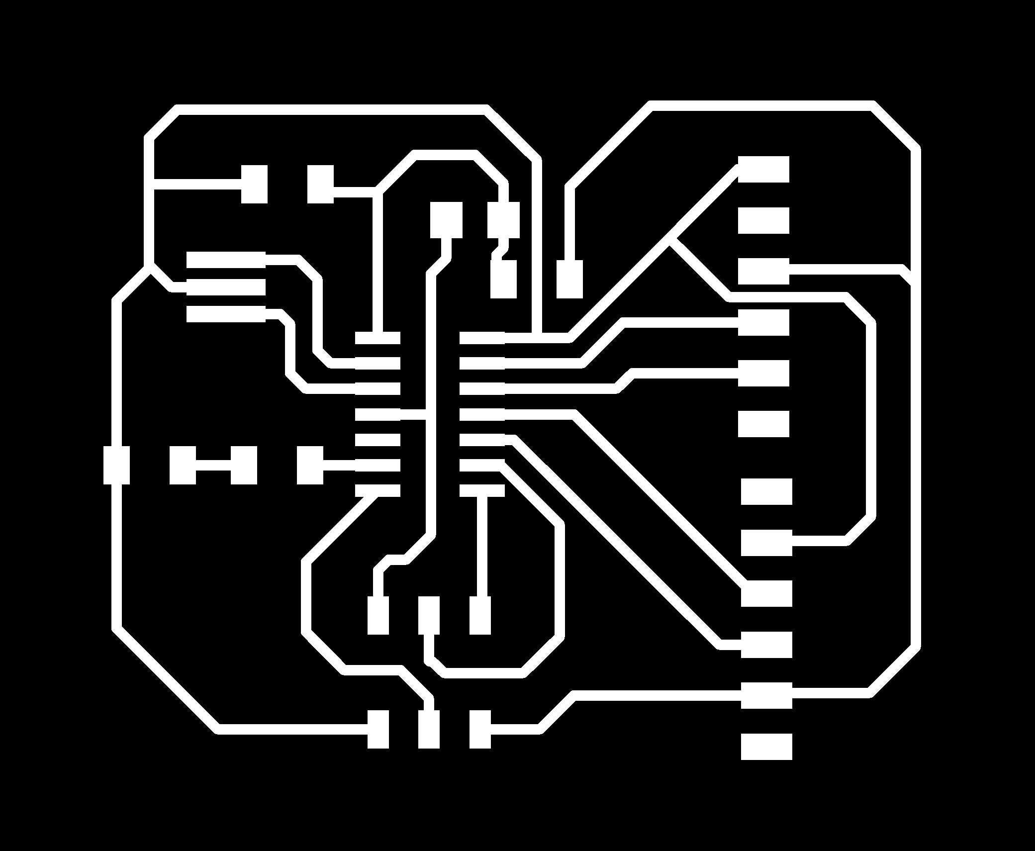
I decided to use an Attiny44 because it has enough pin for testing the inputs devices, this time i also add an FTDI pins for serial communication:
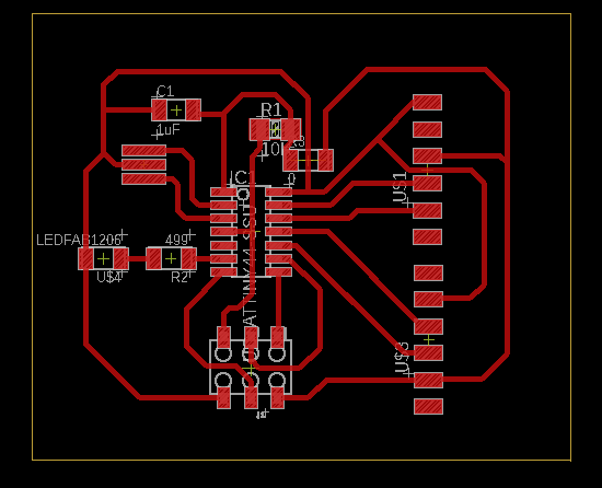
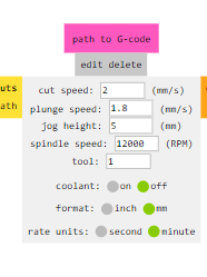
then i exported my design as png and use fab mods as in electronic production week
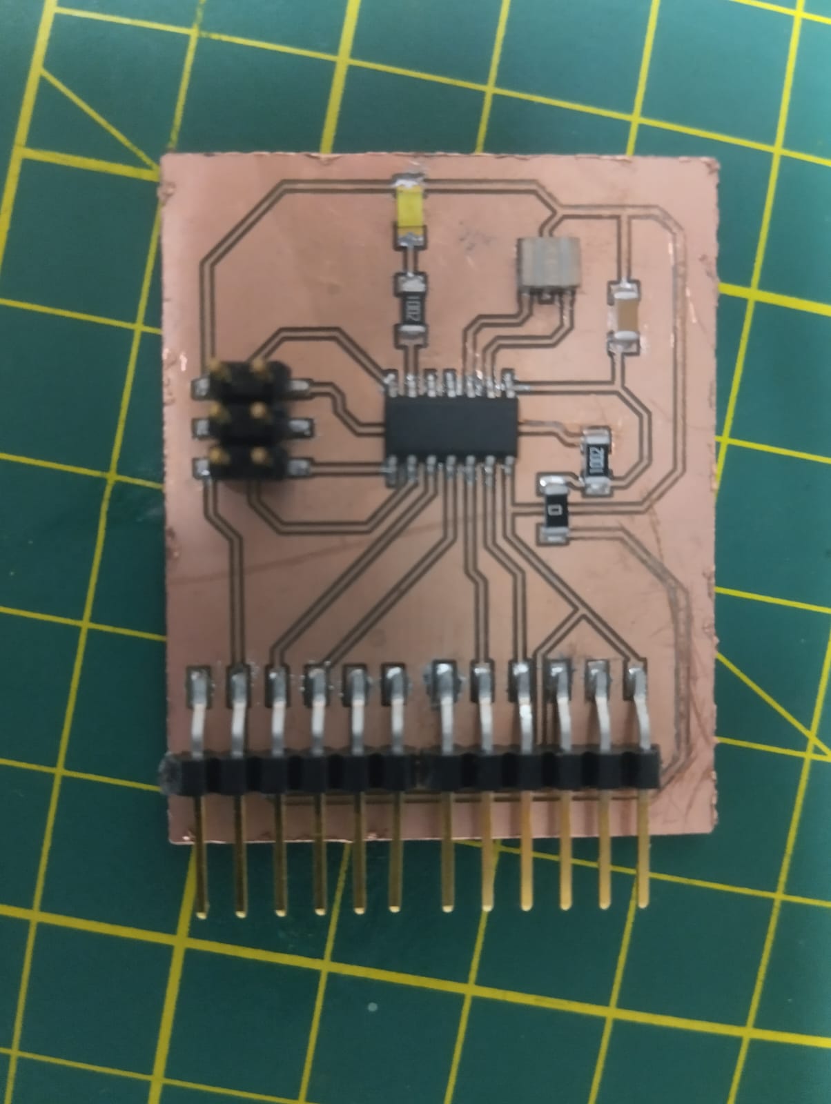
I soldered the components using solder paste:
I decided to test my input pins using a button. So, I program a simple code that turns on a LED every time the button is pressed and also sends its state through serial communication, so I use an FTDI Chip TTL-232R, I checked their data sheet to verify the pins and connected them to my board.
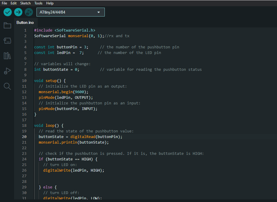
here is the code:
            #include <SoftwareSerial.h>
              SoftwareSerial monserial(0, 1);//rx and tx

              const int buttonPin = 3;     // the number of the pushbutton pin
              const int ledPin =  7;      // the number of the LED pin

              // variables will change:
              int buttonState = 0;         // variable for reading the pushbutton status

              void setup() {
                // initialize the LED pin as an output:
                monserial.begin(9600);
                pinMode(ledPin, OUTPUT);
                // initialize the pushbutton pin as an input:
                pinMode(buttonPin, INPUT);
              }

              void loop() {
                // read the state of the pushbutton value:
                buttonState = digitalRead(buttonPin);
                monserial.println(buttonState);

                // check if the pushbutton is pressed. If it is, the buttonState is HIGH:
                if (buttonState == HIGH) {
                  // turn LED on:
                  digitalWrite(ledPin, HIGH);


                } else {
                  // turn LED off:
                  digitalWrite(ledPin, LOW);
                }
              }
I needed to include "SoftwareSerial.h"" because i`m using an Attiny44 as a microcontroller.
Finally, I decided to test the lm35 as an analog input, for which I programmed a code that reads the lm35 signals and applied an equation to obtain the temperature in Celcius on the serial monitor.
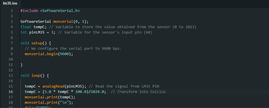
here is the code:
                    #include

                      SoftwareSerial monserial(0, 1);
                      float tempC; // Variable to store the value obtained from the sensor (0 to 1023)
                      int pinLM35 = 3; // Variable for the sensor's input pin (A0)

                      void setup() {
                        // We configure the serial port to 9600 bps.
                        monserial.begin(9600);

                      }

                      void loop() {

                        tempC = analogRead(pinLM35); // Read the signal from LM35 PIN
                        tempC = (5.0 * tempC * 100.0)/1024.0;  // Transform into Celcius
                        monserial.print(tempC);
                        monserial.print("\n");
                        delay(1000);
                      }
Here you can see the lm35 working:
Physical properties such as pressure, temperature, light, or sound are converted into electrical signals, which are then processed by a microcontroller,in a temperature sensor like the lm35, the physical property of temperature is measured by a thermistor or thermocouple, and the resulting electrical signal is processed by the microcontroller to determine the temperature reading.
These are the components that were needed: