Document your work to the group work page and reflect on your individual page what you learned.
Since, There is now one working with me for this week so I have no other project or team member to do the group assignment with him, I decide to talk about the opportunity to talk about two communication methods, SPI and I2C.
An important part is the communication between devices and/or projects, so today I will take the opportunity to talk about two communication methods, SPI and I2C.
SPI (Serial Peripheral Interface):
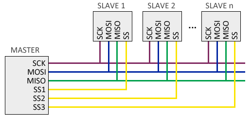
The SPI (Serial Peripheral Interface) bus was developed by Motorola in 1980. It has a master-slave architecture. The master device (master) can initiate communication with one or more slave devices (slave), and send or receive data from them. On the SPI bus, data communication between masters and slaves is carried out on two independent lines, one from the master to the slaves, and another from the slaves to the master. Therefore, the communication is Full Duplex, that is, the master can send and receive data simultaneously.
The SPI bus requires a minimum of 3 lines:
MOSI (Master-out, slave-in) for communication from master to slave.
MISO (Master-in, slave-out) for communication from the slave to the master.
SCK (Clock) clock signal sent by the master.
SPI characteristics:
High transmission speed and Full Duplex.
It can send bit streams of any size, without splitting and without interruptions.
3 cables (SCK, MOSI and MISO) + 1 additional cable (SS) are required for each slave device.
There is no control mechanism available, that is, we cannot know if the message has been received and even less if it has been - received correctly.
I2C (Inter-Integrated Circuit):
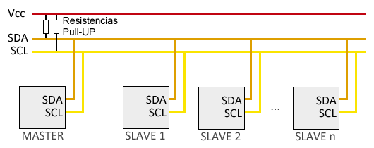
The I2C (Inter-Integrated Circuit) standard was developed by Philips in 1982 for the internal communication of electronic devices in its articles. The I2C bus requires only two cables for its operation, one for the clock signal (CLK) and another for the data transmission (SDA), which is an advantage over the SPI bus. The I2C bus has a master-slave architecture. The master device initiates communication with the slaves, and can send or receive data from the slaves. Slaves cannot start communication (master has to ask them).
The SPI bus requires of 2 lines:
SDA (Serial Data)
SCL (Serial CLock)
I2C characteristics:
Requires few cables
It has mechanisms to verify that the signal has arrived
His speed is medium-low
It isn’t full duplex
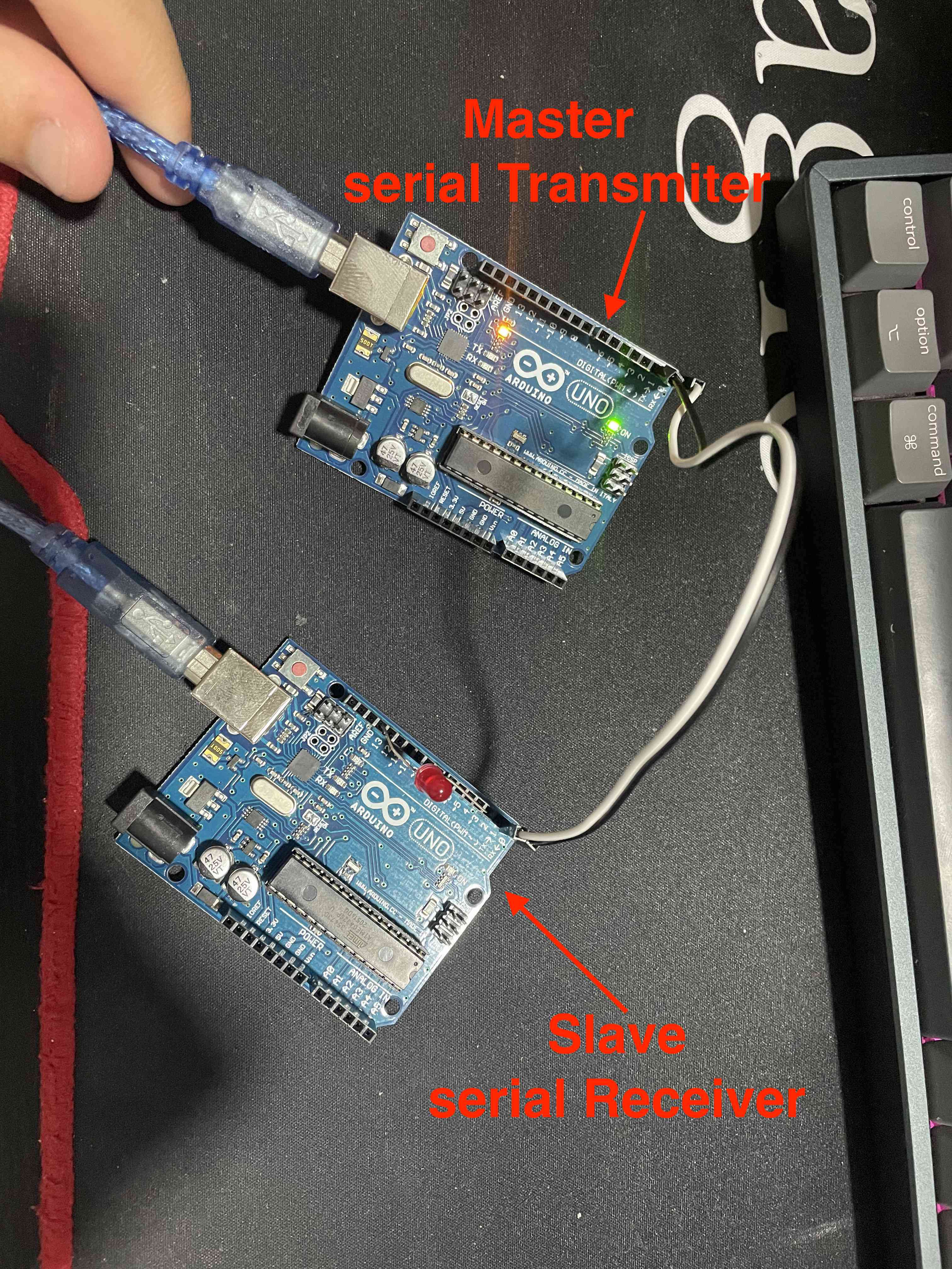
SPI (Serial Peripheral Interface):
for Group assigment I will use SPI method to connect to Arduino UNO board together as one is Master and other is slave, since I use I2C in the Individual assigment.
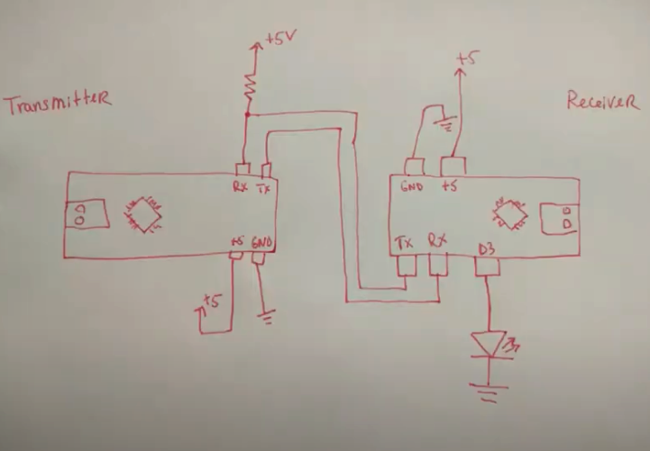
Connection layout
and I connect the RED led to pin 3 in the slave board
Conde it:
Slave code:
String Message;  // Declare a string variable to store incoming serial messages

void setup() {
  Serial.begin(9600);  // Initialize serial communication at 9600 baud
  Serial.setTimeout(50);  // Set the timeout for reading serial data to 50 milliseconds (default is 1 second)
  delay(100);  // Delay for stability
  pinMode(3, OUTPUT);  // Set digital pin 3 as an output
}  // setup

void loop() {
  // put your main code here, to run repeatedly:

  if (Serial.available()) {
    Message = Serial.readString();  // Read the incoming serial message and store it in the 'Message' variable
  }

  delay(4);  // Introduce a small delay to avoid continuous checking and improve performance

  if (Message == "on") {
    digitalWrite(3, HIGH);  // If the received message is "on", set digital pin 3 to HIGH
  }

  if (Message == "off") {
    digitalWrite(3, LOW);  // If the received message is "off", set digital pin 3 to LOW
  }
  // Message = "\0";  // Uncomment if you want to reset the Message variable after each loop iteration
}  // loop
Master code:
String Message;  // Declare a string variable to store incoming serial messages

void setup() {
  Serial.begin(9600);  // Initialize serial communication at 9600 baud
  delay(100);  // Delay for stability
}

void loop() {
  // Print "on" and "off" messages to serial every 2.5 seconds
  Serial.print("on");
  delay(2500);
  Serial.print("off");
  delay(2500);

  // Check if there's any serial data available
  if (Serial.available()) {
    Message = Serial.readString();  // Read the incoming serial message and store it in the 'Message' variable
  }

  // Uncomment the line below to print the received message to the serial monitor
  // Serial.println(Message);
}
Code Explanation:
The idea behind these Arduino code snippets is to showcase a simple serial communication scenario between two Arduino programs. The first code snippet is intended to control a digital output (pin 3) based on the messages received through the serial port. The second code snippet is a simple sender that continuously sends "on" and "off" messages to the serial port every 2.5 seconds.
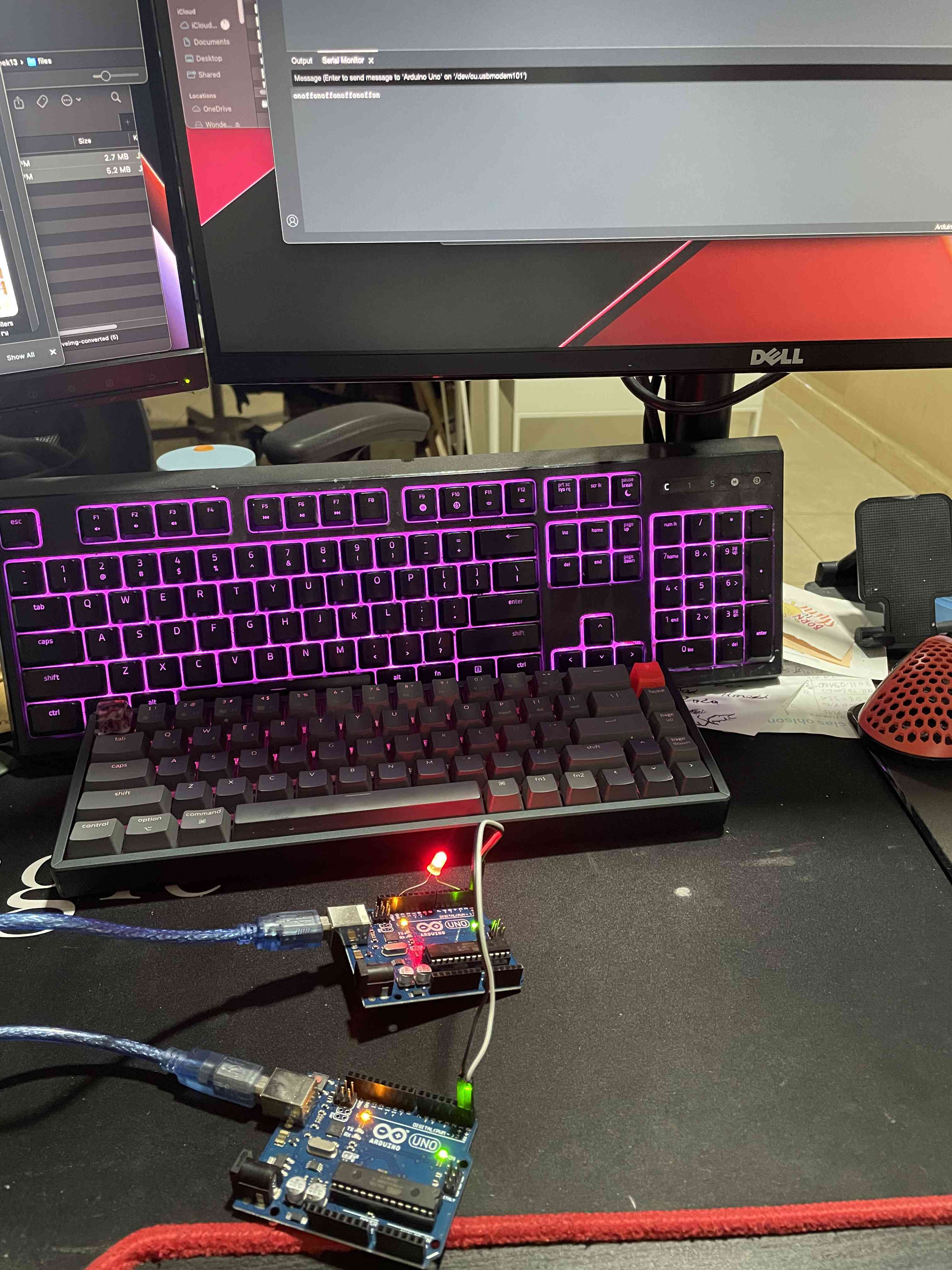
Test it :
Files:
Please find the attached files :
File
Link
Master Code:
Slave Code:
Individual assignment:
Design, build, and connect wired or wireless node(s) with network or bus addresses
For this assignment, we need another PCB so now we will have two PCBs, if you are interested in knowing how this PCB was made you can check week 7 and week 9.
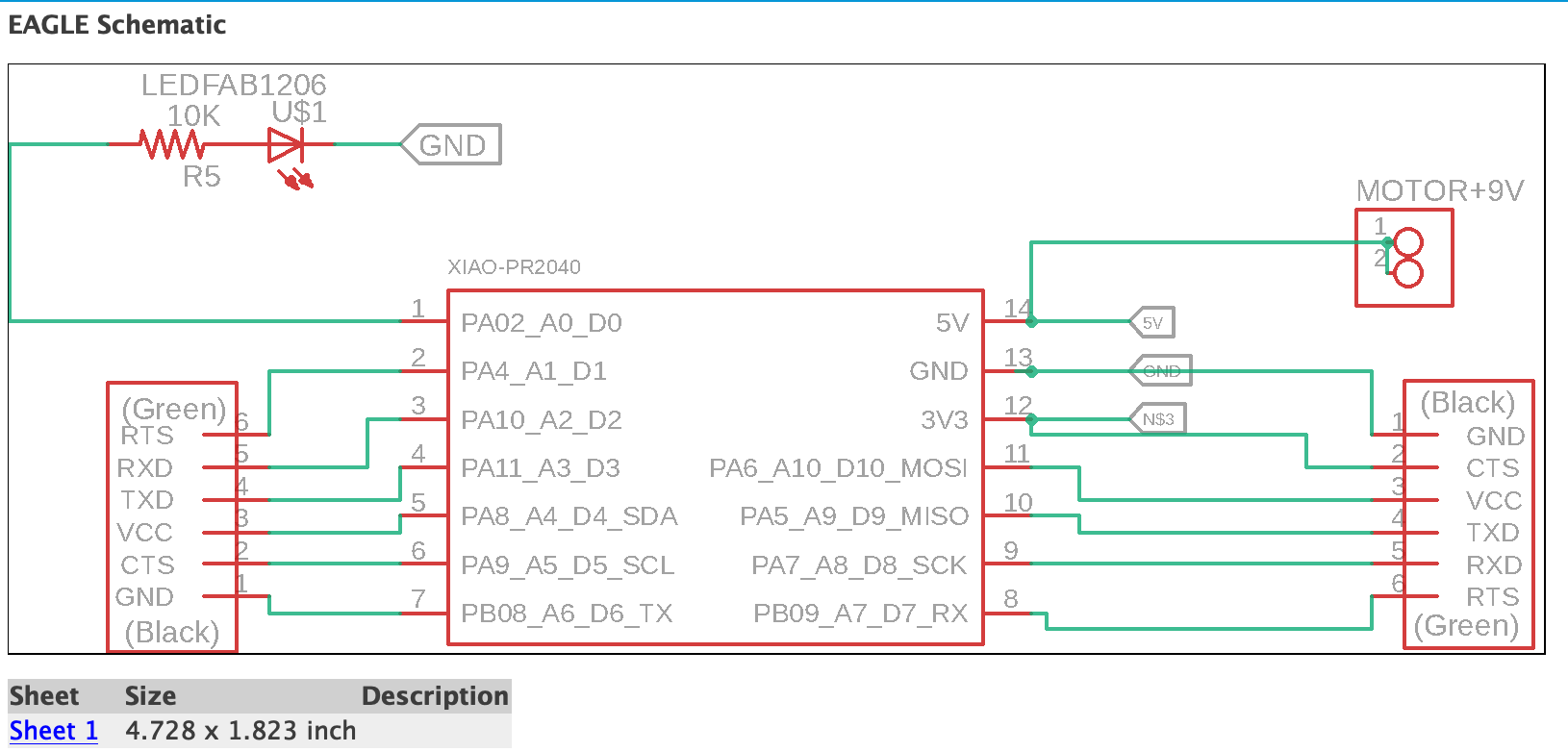
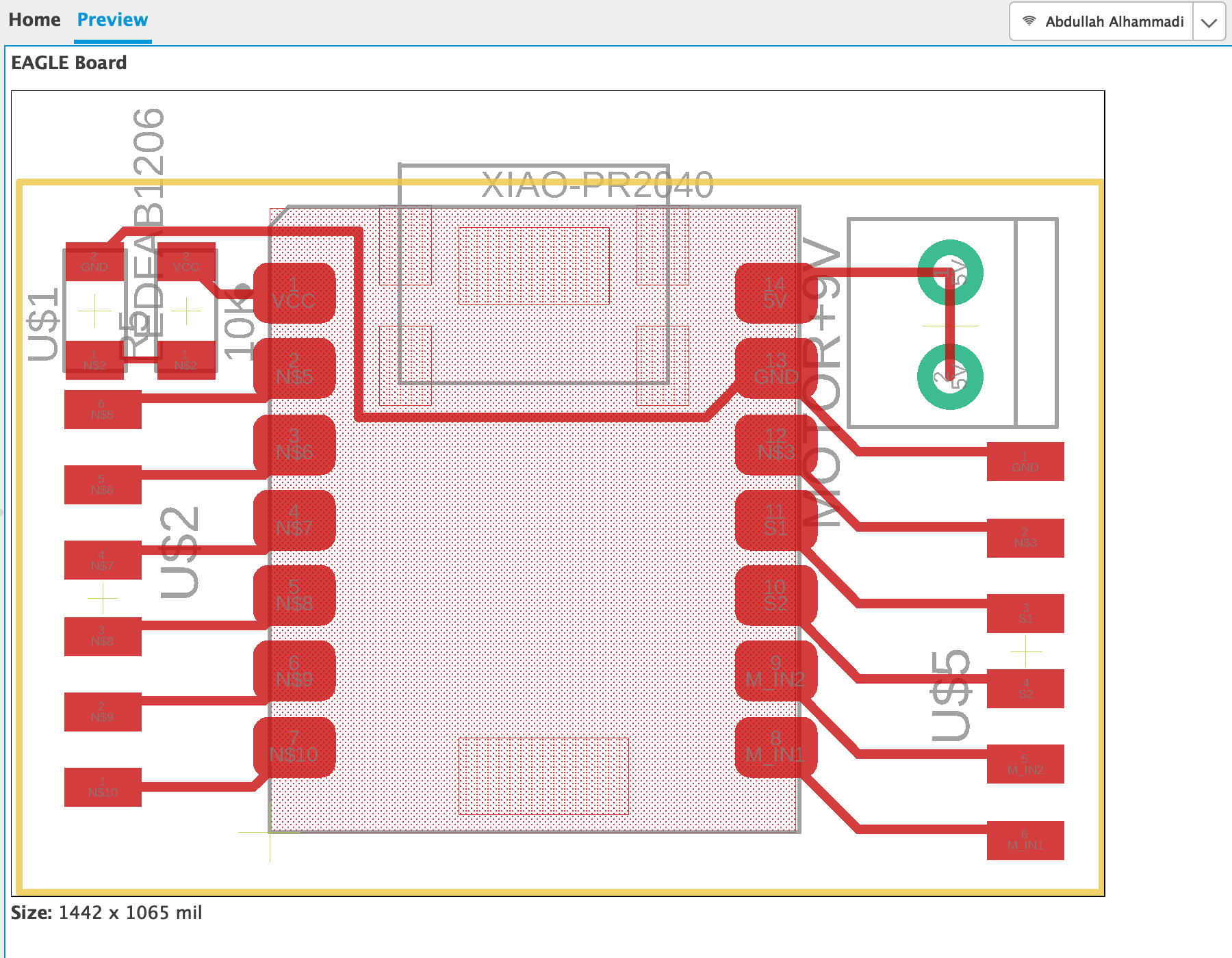
And for the second PCB I made a simple one in Eagle and cut it ans solider it for this week since we need master and slave board.
Also, I use other components: - 1 Blue LED. - 4 Copper wire.
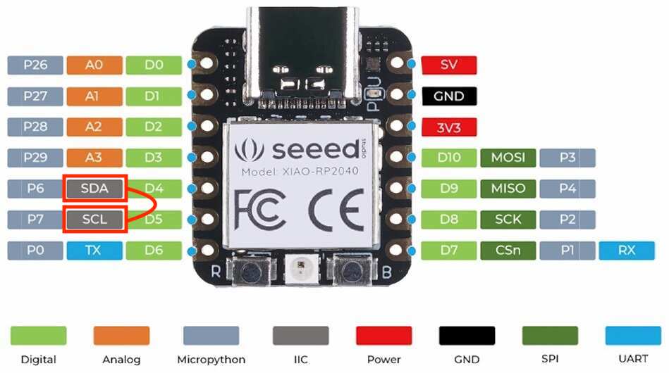
I will use I2C
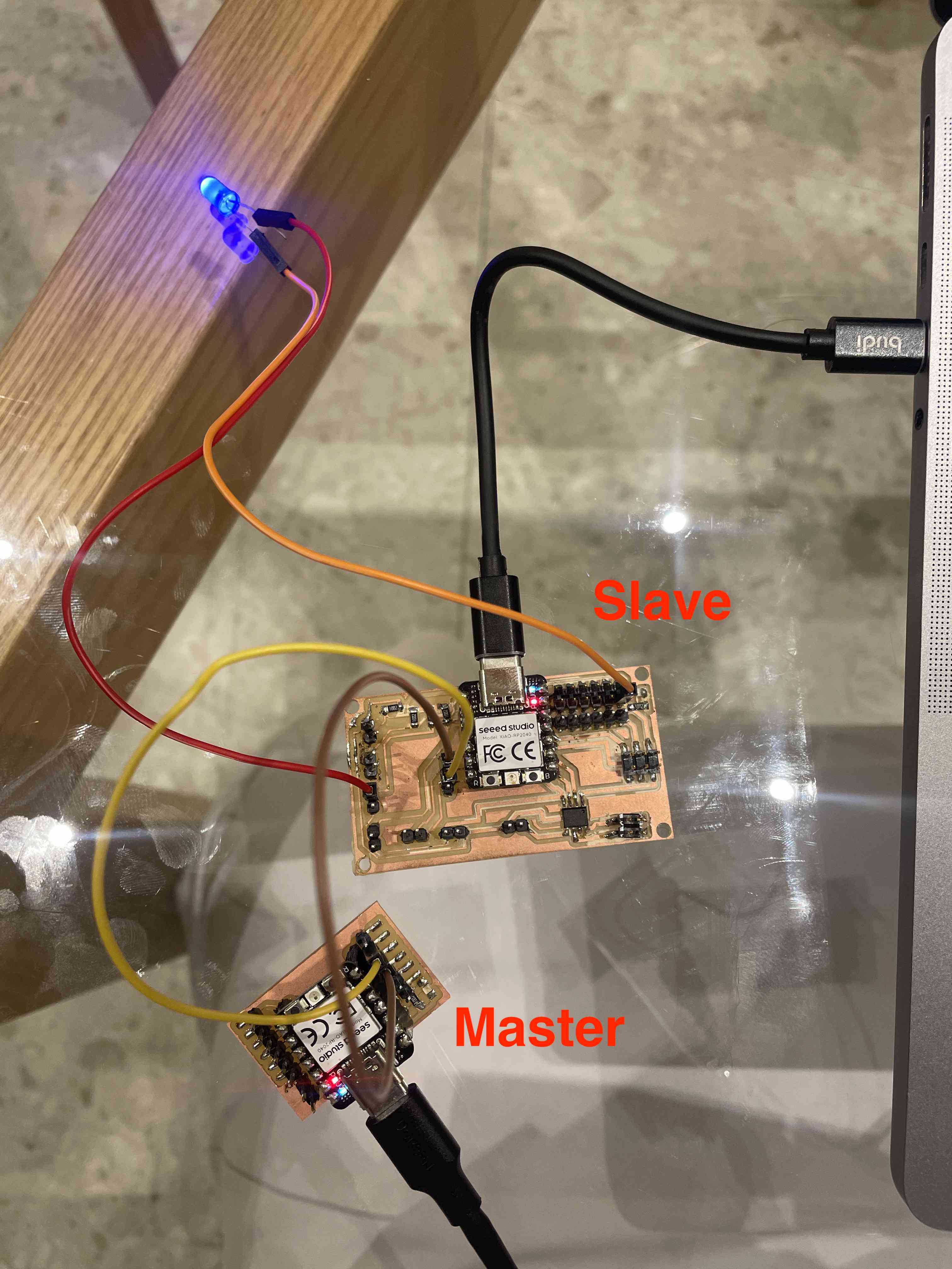
The goal is to establish communication between two boards by connecting them through their SDA and SCL pins. The code functions in the following manner: when the master sends the character 'O' to the slave, it triggers the LED to switch to the 'ON' state, and if the master sends 'F', it prompts the LED to transition to the 'OFF' state.
connect this 2 port in both board to gether, you have to ensure that you have the proper connections between the SDA and SCL pins of the master and slave boards. Also, connect the ground (GND) pins between the two boards.
Final connection:
Slave code:
#include

void setup() {
  Wire.begin(9);                  // Initialize I2C communication as Slave with address 9
  Wire.onReceive(receiveEvent);   // Register event function for incoming data
  Serial.begin(9600);              // Initialize serial communication
  pinMode(D1, OUTPUT);
}

void loop() {
  // Additional processing can be done in the loop if needed
}

void receiveEvent(int bytes) {
  char receivedChar = Wire.read();  // Read the character sent by the master
  Serial.print("Received character: ");
  Serial.println(receivedChar);

    if (receivedChar == 'O') {
        digitalWrite(D1, HIGH);  // Assuming D1 is the correct pin
      } else if (receivedChar == 'F'){
        digitalWrite(D1, LOW);   // Assuming D1 is the correct pin
      }
  // Add your logic based on the received data
}
Master code:
#include

void setup() {
  Wire.begin();        // Initialize I2C communication as Master
  Serial.begin(9600);  // Initialize serial communication
}

void loop() {
  Wire.beginTransmission(9);  // Address of the slave
  Wire.write('O');           // Send a character to the slave
  Wire.endTransmission();     // Stop transmitting

  delay(2000);  // Wait for a second before sending the next command

  Wire.beginTransmission(9);  // Address of the slave
  Wire.write('F');           // Send a character to the slave
  Wire.endTransmission();     // Stop transmitting
    delay(2000);
}
Code Explanation
The provided code establishes communication between a master and a slave device using the I2C protocol. The master device, initialized with the address 9, sends two distinct characters ('O' and 'F') to the slave device at regular intervals. The slave, upon receiving these characters, interprets 'O' as a command to set a designated output pin (D1) to a high logic level and 'F' as a command to set the same pin to a low logic level. This enables the master to remotely control the state of an output on the slave device through the I2C communication channel. The receiveEvent function in the slave code reads the received character, prints it to the Serial Monitor for debugging purposes, and then executes the corresponding logic to control the output pin based on the received command. This code serves as a simple example of how I2C communication can be used for remote control or data exchange between Arduino devices.