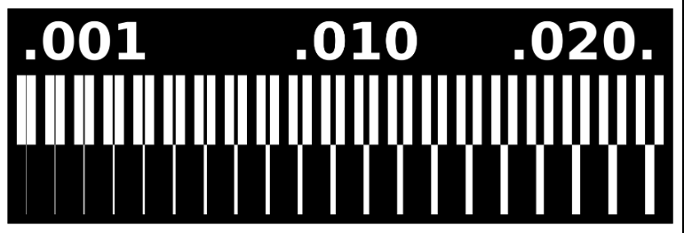
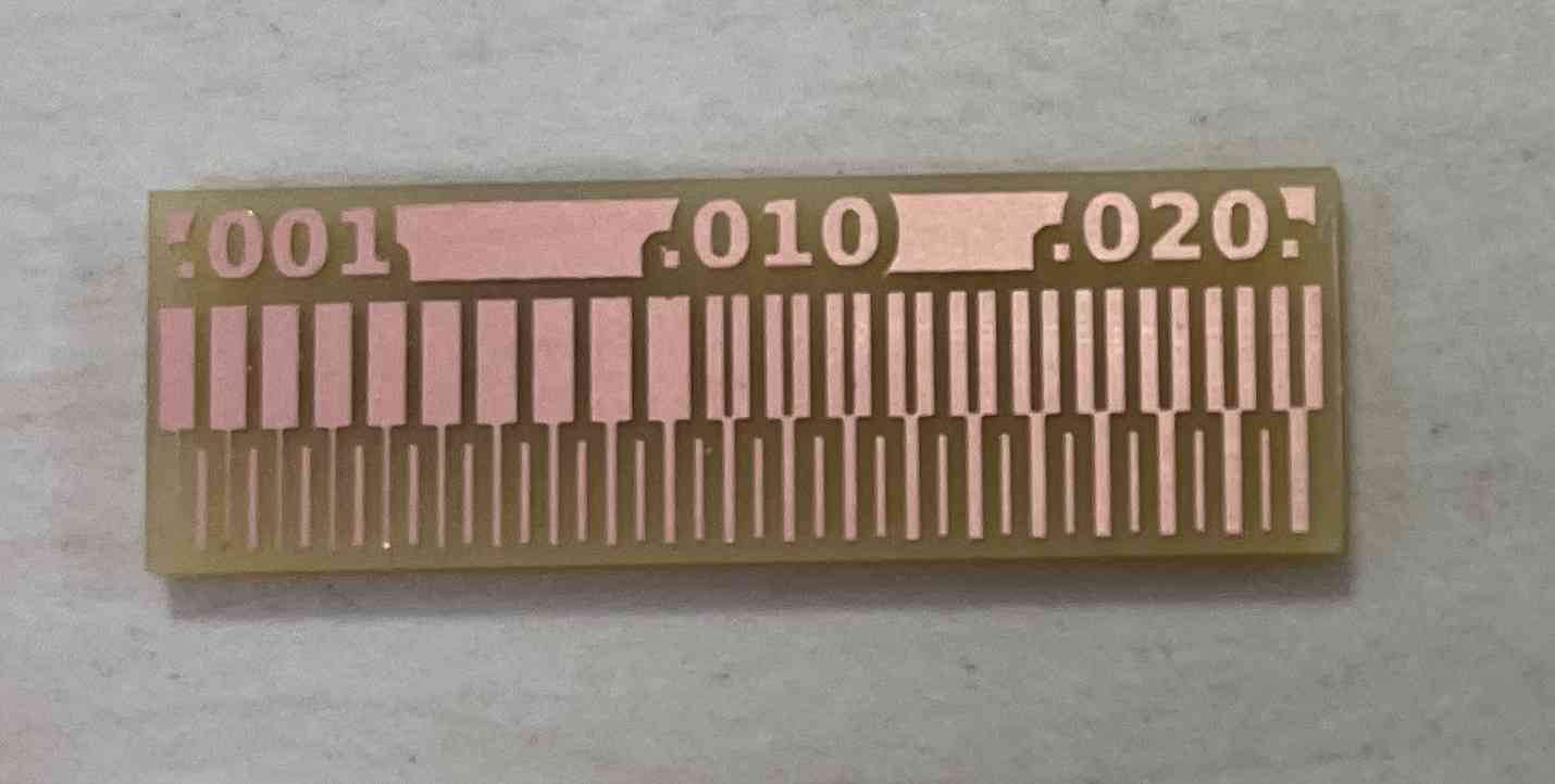
I used ready made "trace width" test click for reference, test images were already (traces and outline), these images shows exactly carves that will be in the bored. What I need to do is open fab mods to convert test images into formate understandable by the machine that includes the movements of the machine need to do it to produce the bore
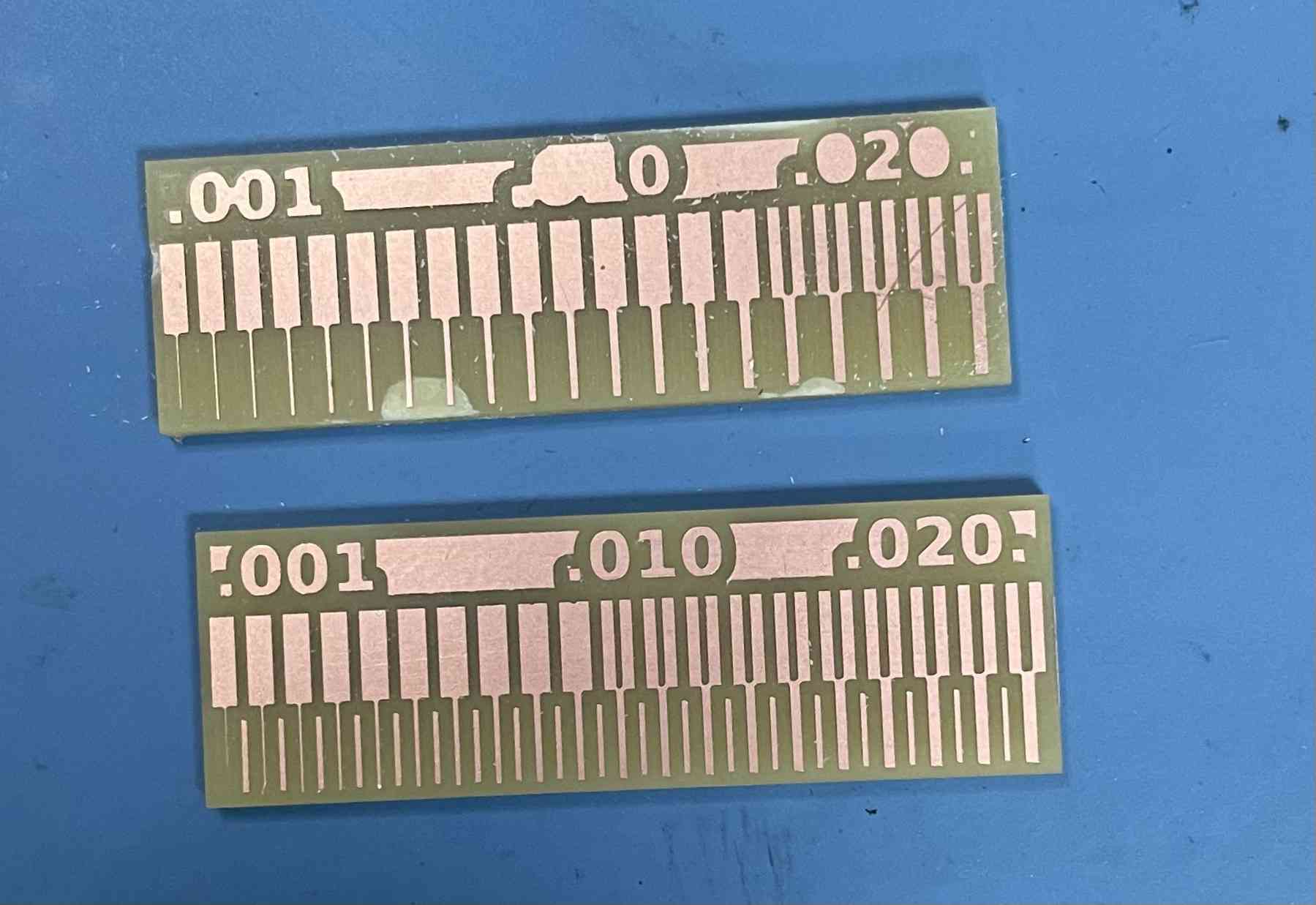
For the group assignment we tried milling using two different milling bits (0.01 & 1/64) I used "mods" to calculate PCB traces and use it for milling
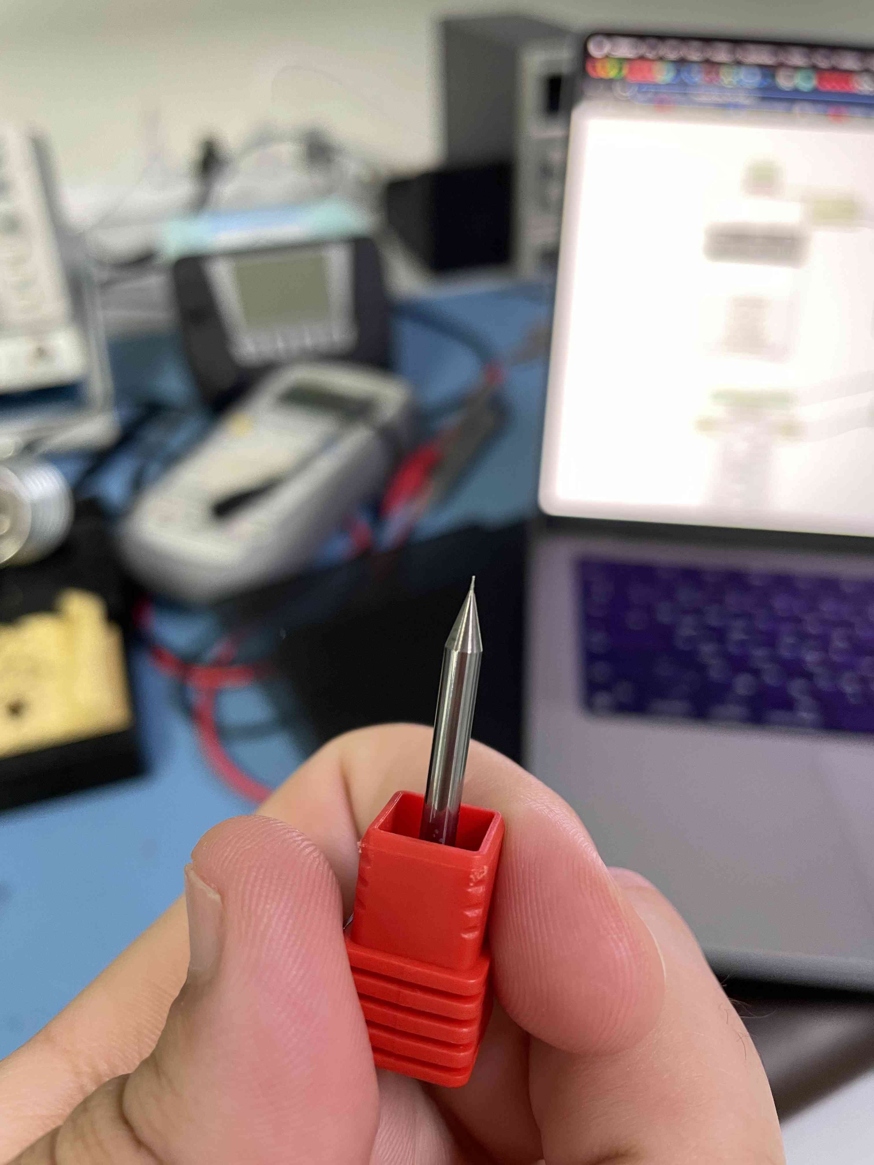
milling bits (0.01)
MODs steps:
Open the Mods page and follow the tutorial mentioned in the fab academy page.
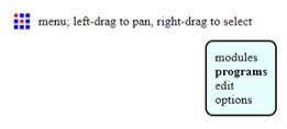
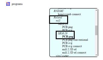
Right click on the page and chose program
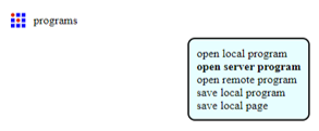
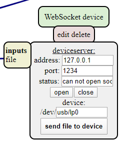
After that a new screen will appear and we will choose open server program
We need to select the machine and its type so our machine is Roland mill (SRM 20) so I chose it as shown below
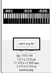
The new screen will appear where I required to add a png file
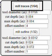
I clicked on mill traces (1/64)
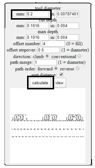
I changed the tool diameter to be 0.01 mm then clicked calculate and the below picture will appear
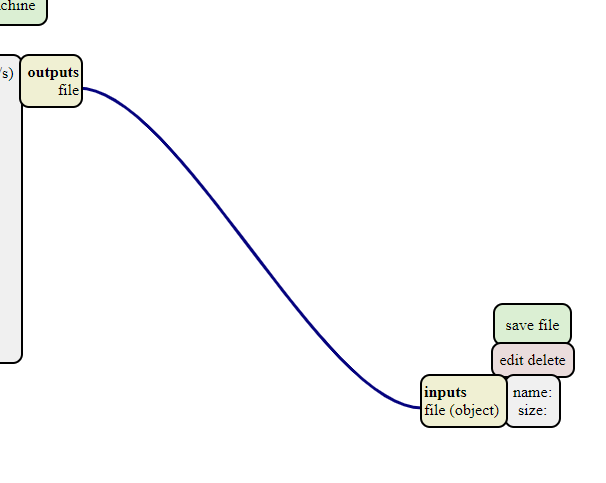
I need to delete the input that is connected with the output so I clicked on delete
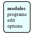
Right Clicked on the page and chose modules
Then I chose open server modules >> file save. Then the new input will appear so we connect it with the output as shown below
I recalculated the process and then the file will be saved automatically on my computer.
I fixed the xyz points on the roland machine and make sure they are in the right place after that I entered the file and clicked on cut to start the milling process.
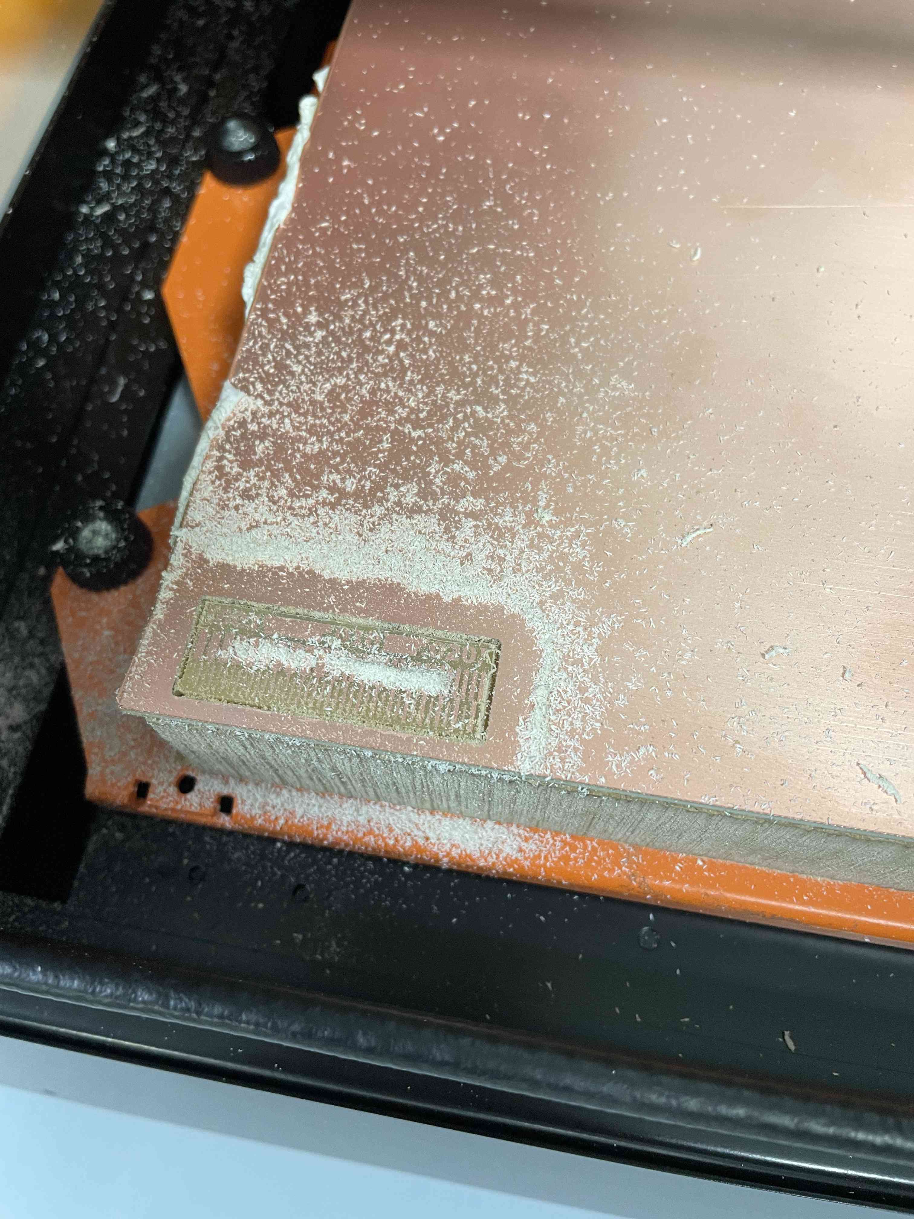
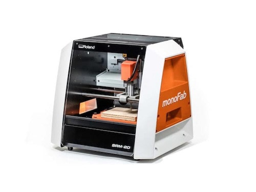
After calculate the PCB traces I start cutting the PCB using monoFab CNC machine
Compering the difference between milling bits (0.01 & 1/64)
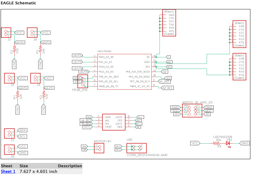
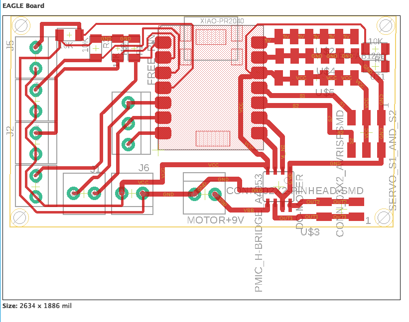
For this week’s task, we will Fabricate PCB for RP2040. Afterward, I’m going to use it in my Fab academy Journey. Moreover, we took this chance to learn the steps of the electronic production of PCB.
There are many techniques can be used to Fabricate PCBs and today I will use "Fabricate PCB using a CNC machine".
1. Fabricate PCB using a CNC machine.
The technique I try this week was Milling which is a machine cut or shape materials using a rotating tool.
In the lab we are having Roland SRM-02CNC Machine its working based on milling technique , and CNC stand for Computer Numerical Control the picture below shows the machine:
Fab modules create .rml file because we did use a Roland machine that includes the movements of the machine need to do it to produce the bored.
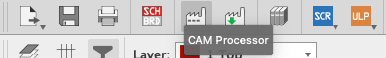
First, we have to go to "CAM Processor" in Eagle
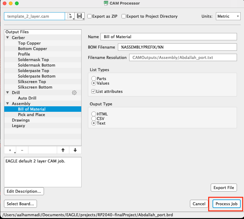
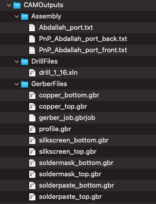
2ed, we have to click on "Process job"
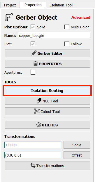
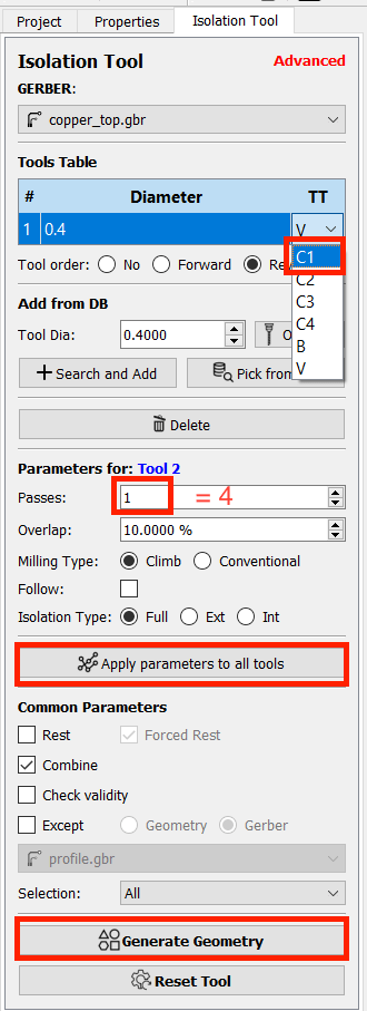
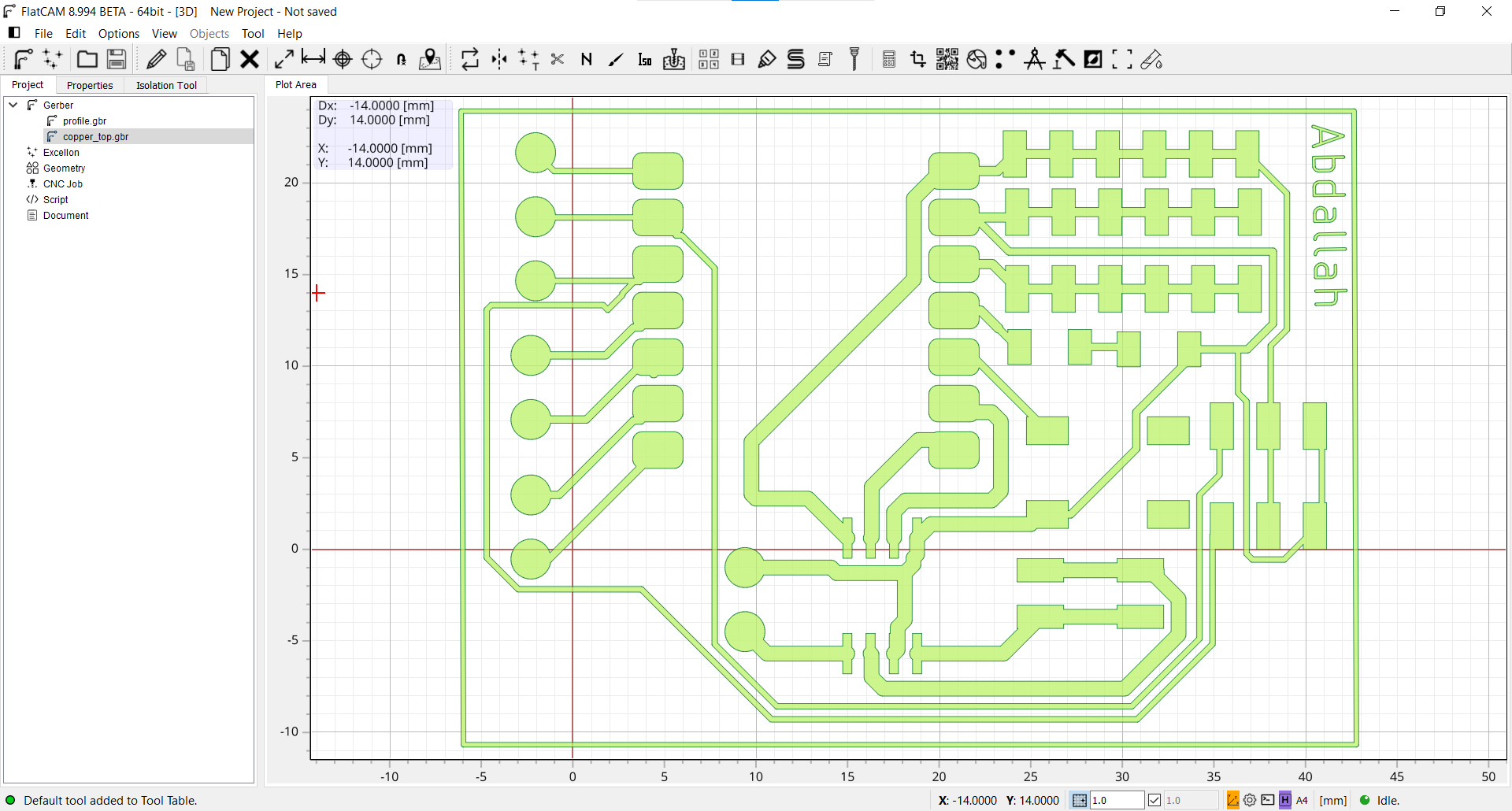
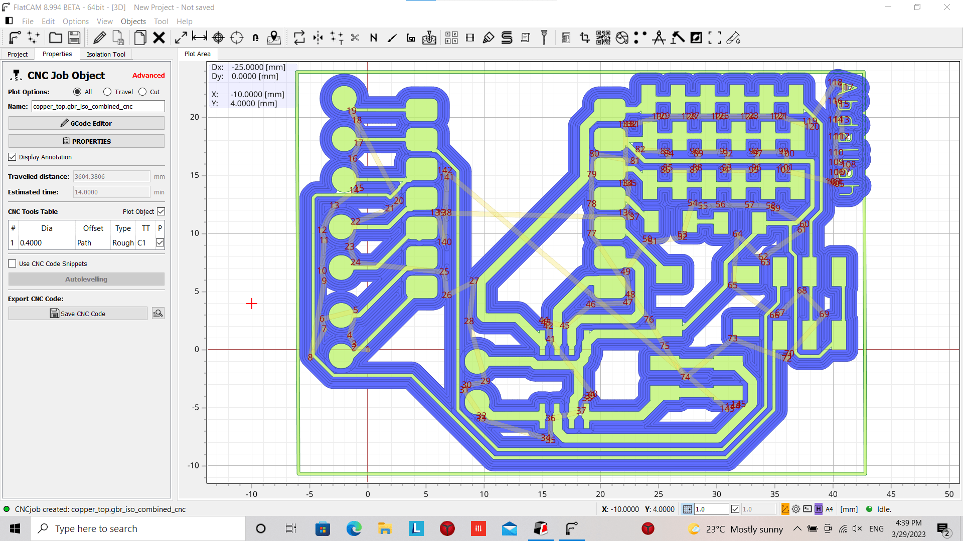
Now we have to open FlatCAM to generate the trace path
Set thge tool diameter (0.4 mm (to cut the copper top) & 0.8 mm (to cut the progile & holds)) in "FlatCAM" after opening the CAM process file
let start with the copper top. (0.4mm) (1/64)
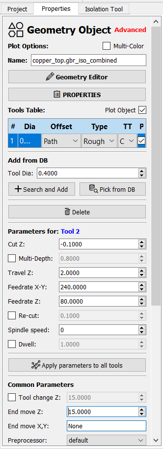
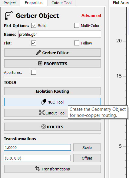
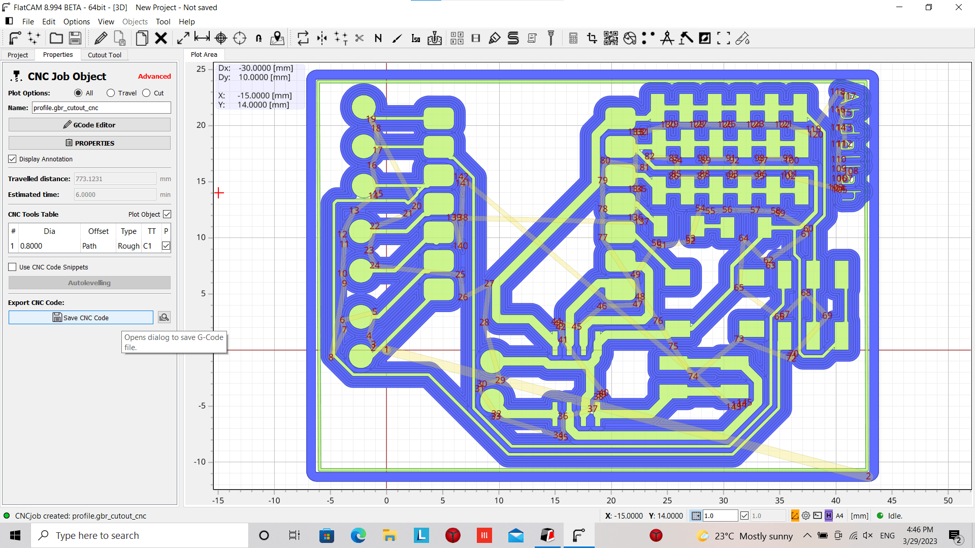
Now we will do the profile. (0.8mm) (1/32)
set the tool dia to (0.8mm) (1/32) and set the Isolation Routing and NCC Tool
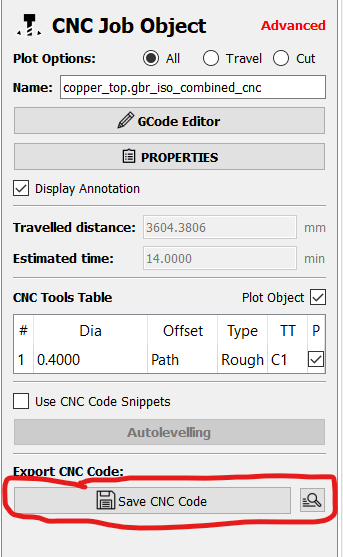
Now we have to save it and but run the CNC machine
PCB Milling Steps:
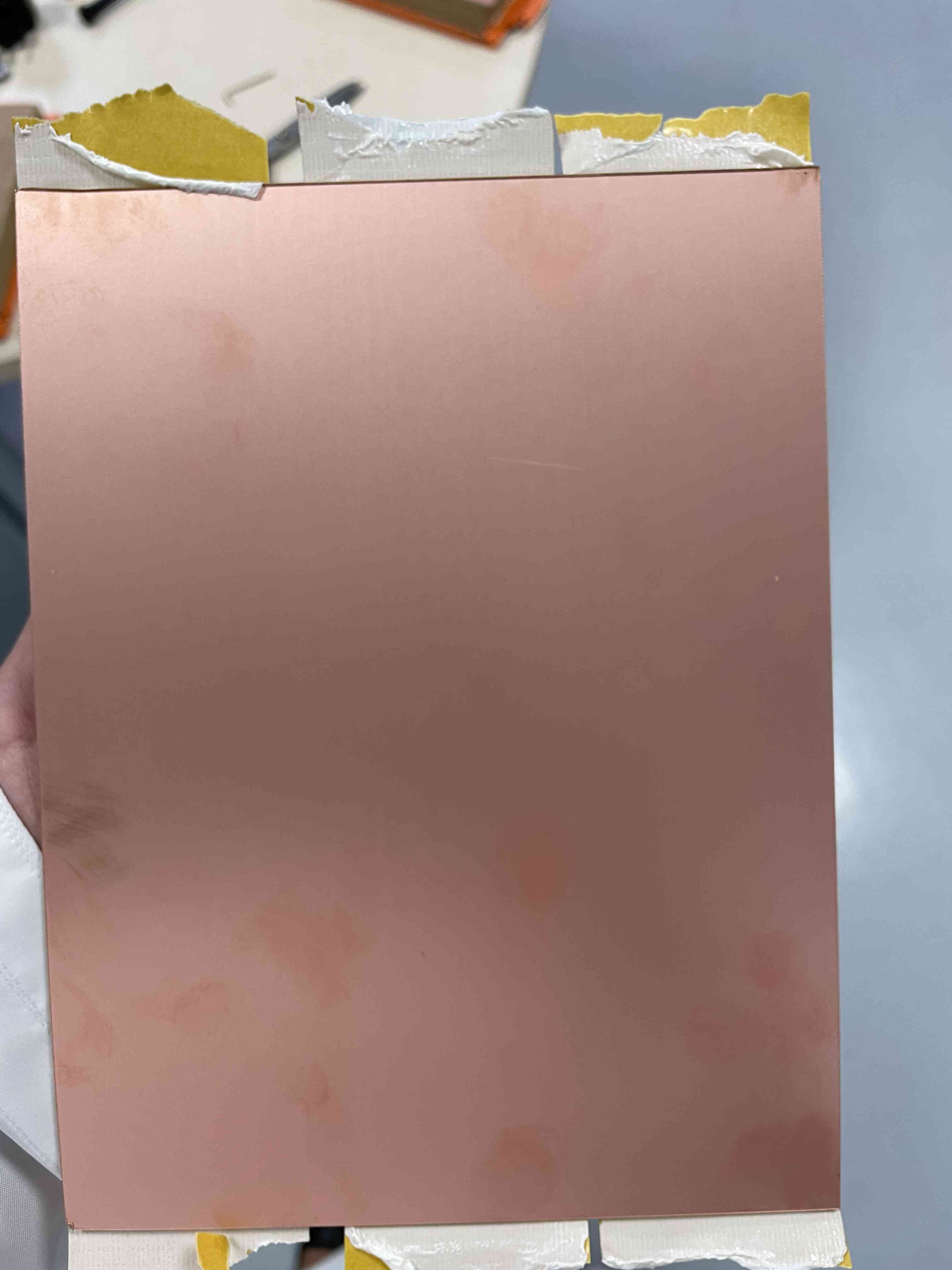
Fixing FR1 in the machine.
As we will use the same FR1 sheet to save materials & avoiding any waste, so we did The set up together.
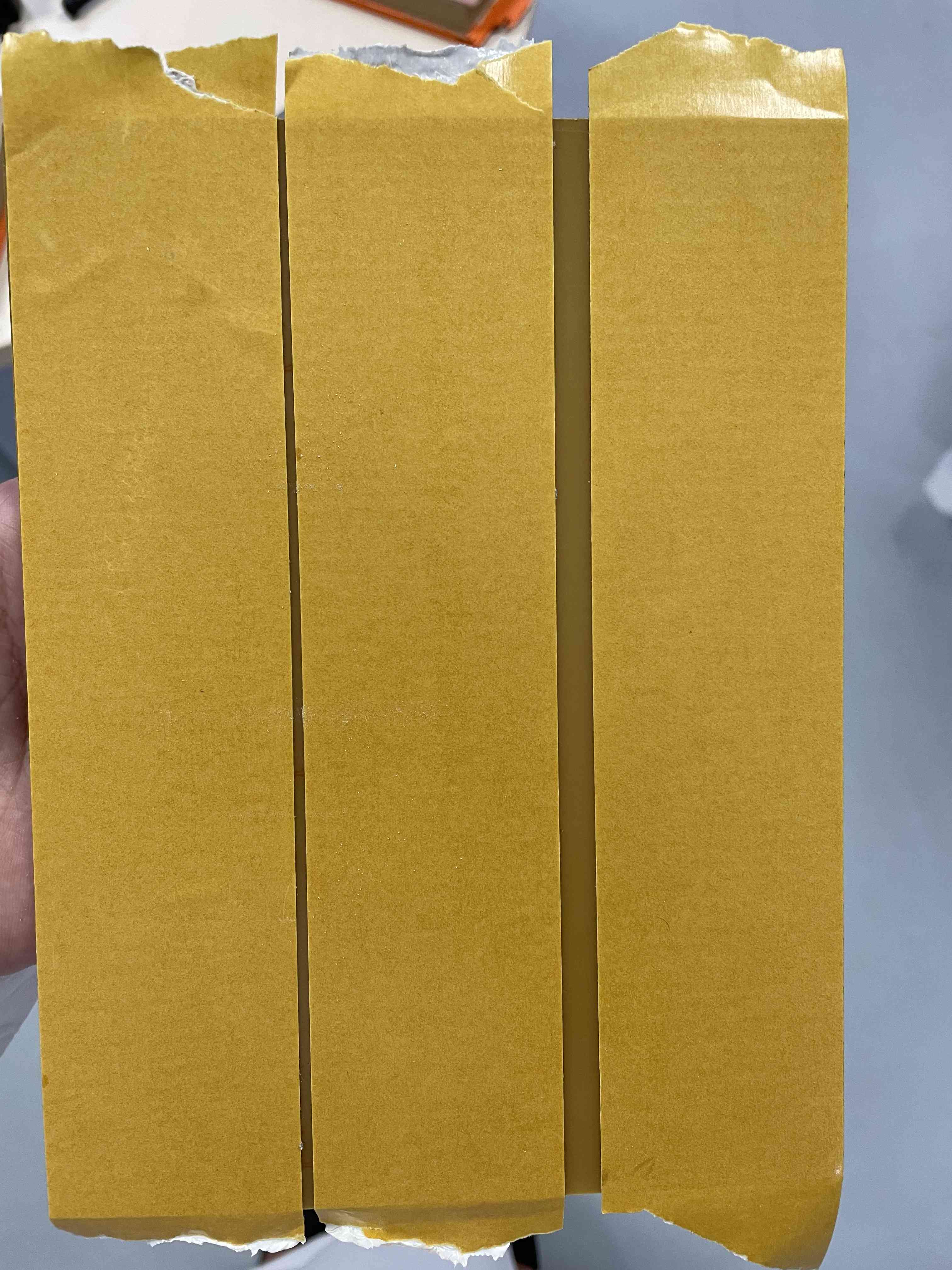
Place double sided tape in back of Fr1 sheet & Make sure there is no any in bubbles in the tape and its flat.
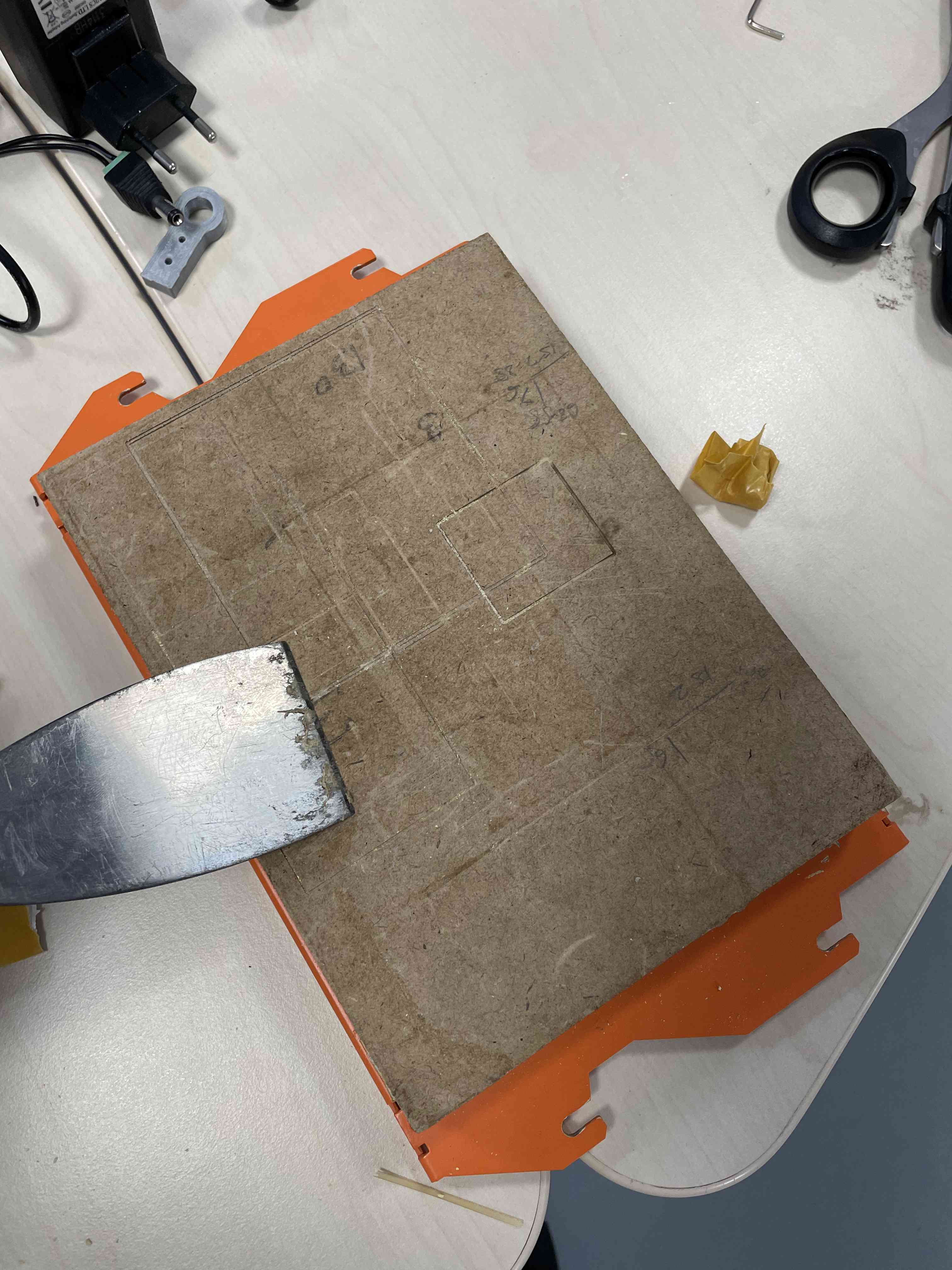
open the double sides tap and Stick the sheet in MDF bored of the machine after cleaing the MDF.
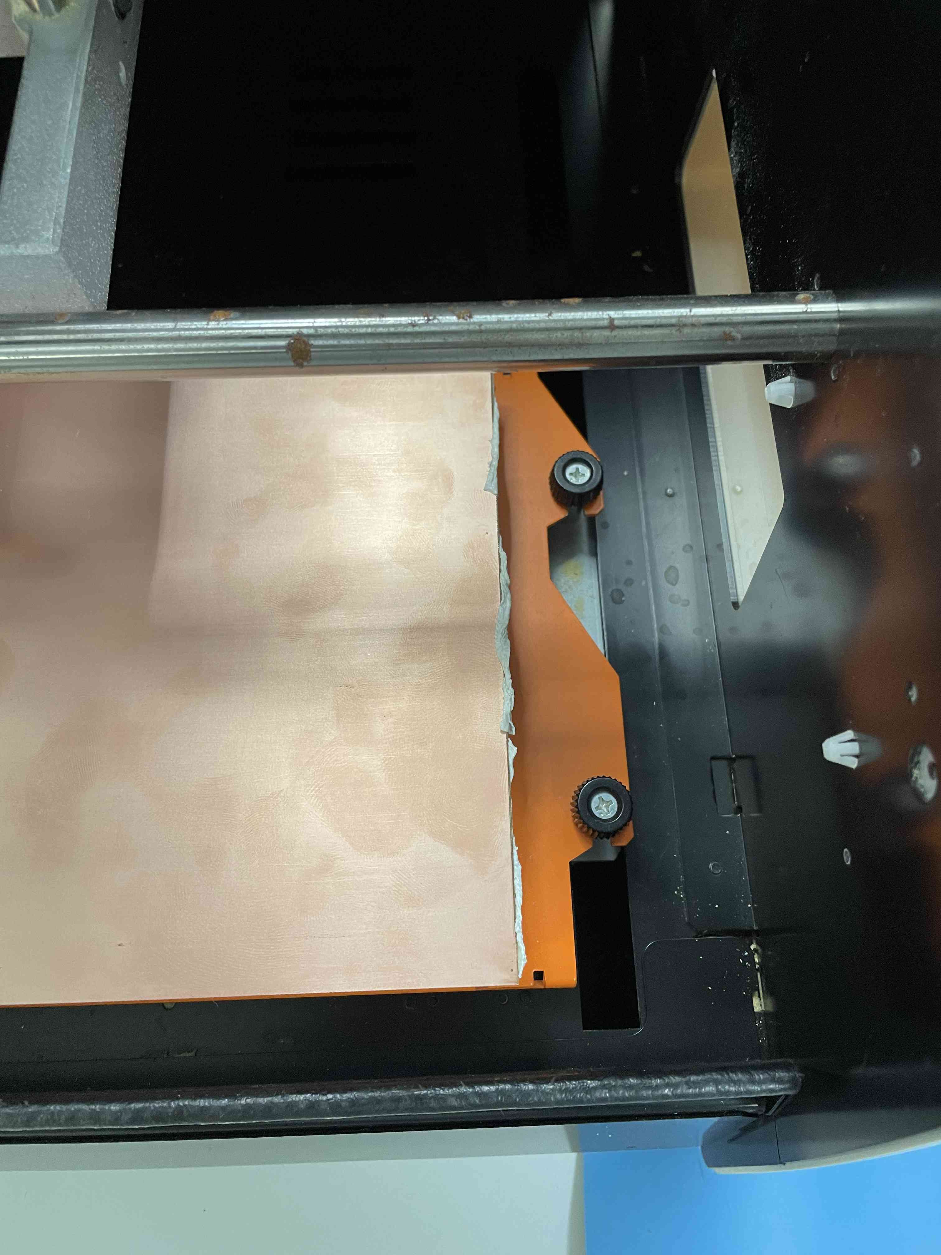
Finally, Place the MDF bored in the machine by screwing the corners.
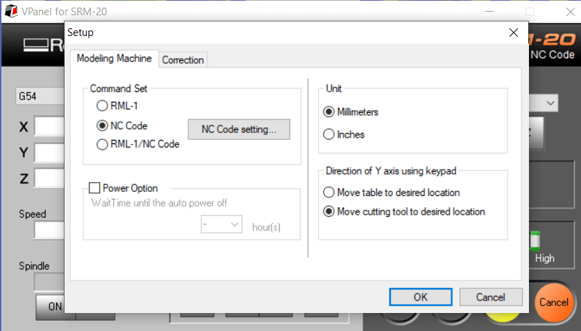
First, we have to ensure that the "Command Set " to "NC Code"
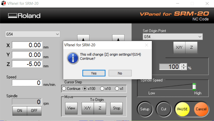
The pictures show the steps of milling the traces. First, I did use milling bit size 1/64 inch ,and, I use V-panel for SRM-20 to set the origin point for X Y Z ,whenever I’m done I press cut and add trace file.
Now we can start the CNC machine.
For the outline is the same steps but I changes the milling bit to 1/32 inch, and I only set Z origin without changing X and Y , Finally I took out the PCB out.
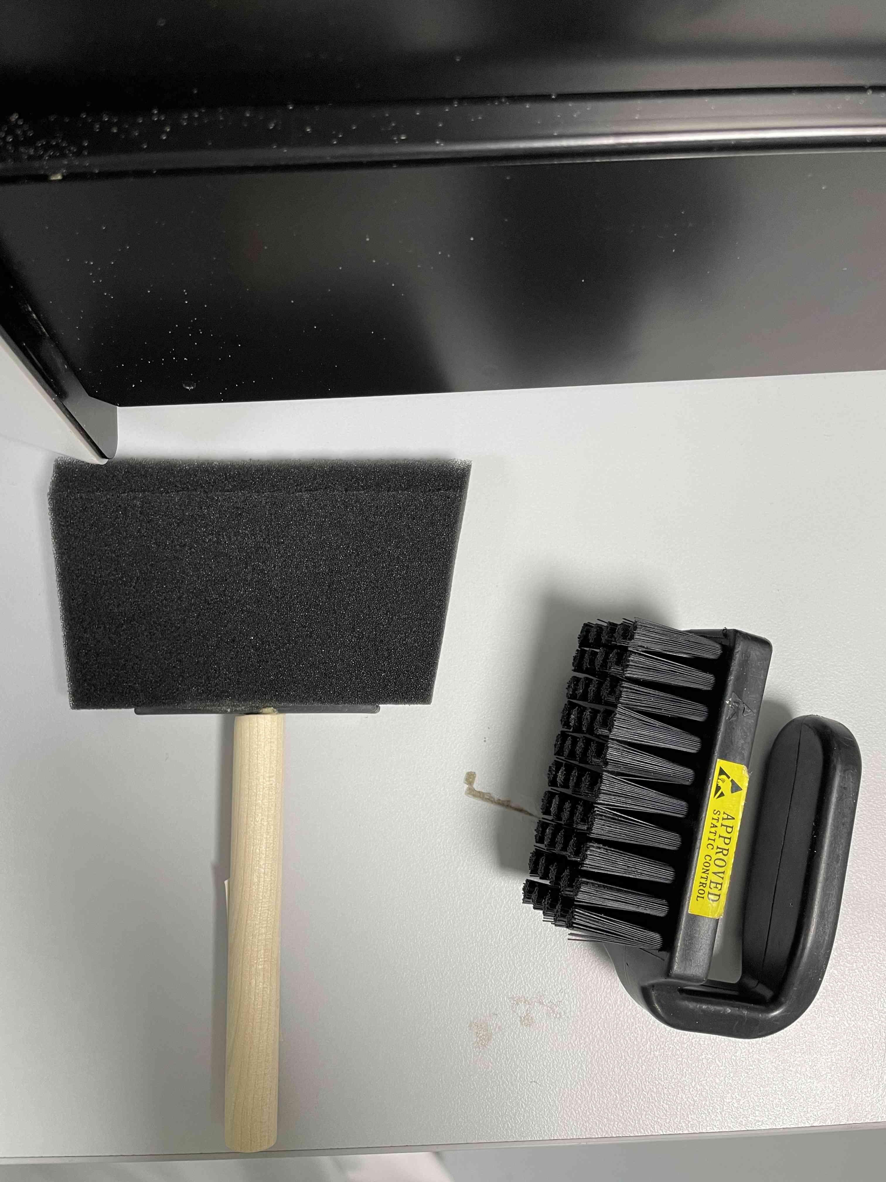
when the PCB pord was ready I cleaned it using those tools before removing it from the FR1.
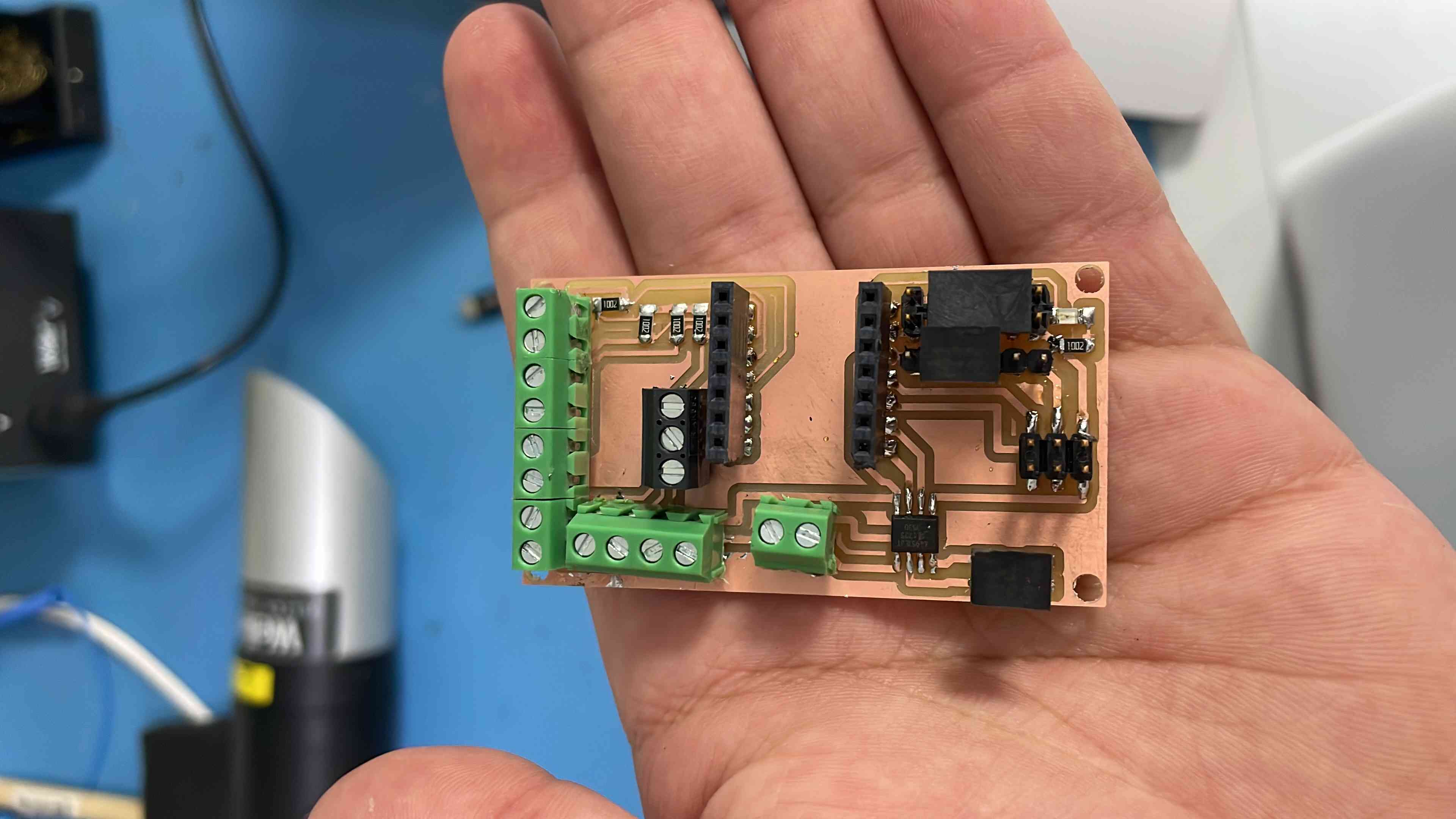
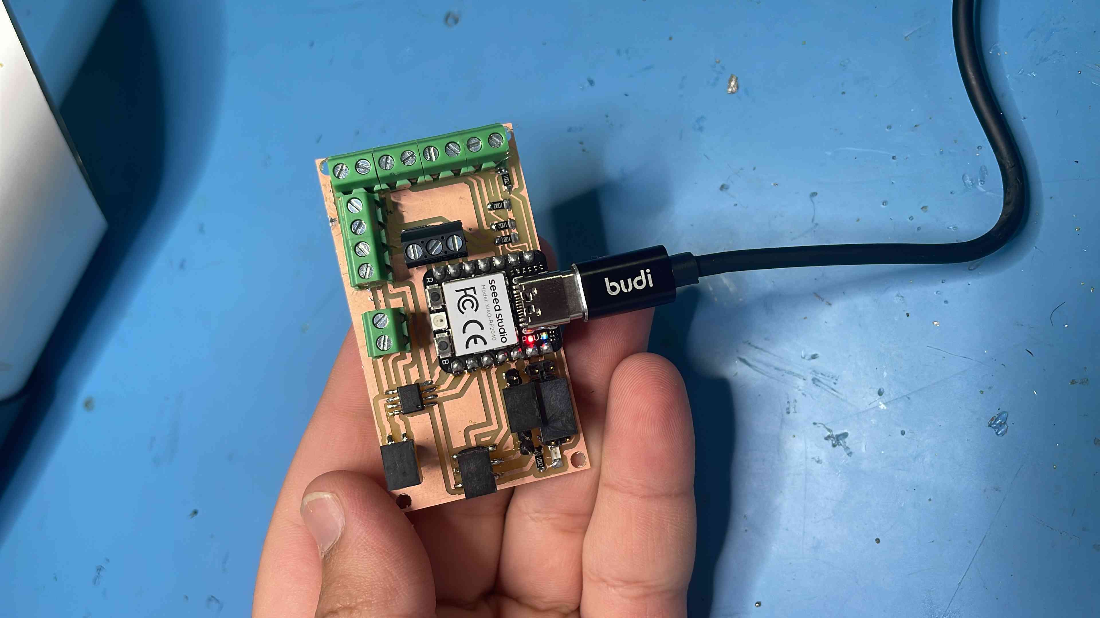
Finally My PCB is Ready, Now I can start Soldering
Final PCB Pord:
Testing PCB Pord:
Tested Code - with servo: :
#include "Servo.h"

Servo myservo;  // create servo object to control a servo
// twelve servo objects can be created on most boards

int pos = 0;    // variable to store the servo position

void setup() {
  myservo.attach(D0,540,2400);  // attaches the servo on pin 9 to the servo object
}

void loop() {
    myservo.write(0);              // tell servo to go to position in variable 'pos'
    delay(1000);                       // waits 15ms for the servo to reach the position
    myservo.write(90);
    delay(1000);                       // waits 15ms for the servo to reach the position
    myservo.write(180);
    delay(1000);
  }

