Week11: input devices
Input devices:
This week’s assignment is centered around electronics input devices. "Input devices" include any kind of analog or digital sensor that can be interfaced with a microcontroller.
Different types of sensors:
A sensor is a hardware device that is able to measurement a physical properties (like temperature, pressure, magnetic field). The data that is generated / measured by a sensor is usually in analogue form.
We can distinguish 4 main categories: active vs passive sensor and digital vs analogical
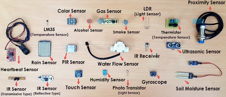
Below a list of sensors (not exhasutive):
Group assignment:
Probe an input device's analog levels and digital signals
Individual assignment:
Measure something: add a sensor to a microcontroller board that you have designed and read it.
For this individual assignment, we received the following rules from our tutor about what we can or cannot do / use this week to deliver the individual assignment:
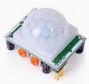
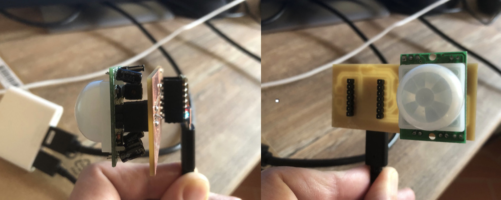
For the assignment, I have decided to use a PIR sensor which work by detecting infrared light given off by a moving object or person that emits heat. This PIR sensor will be required in the architceture of my final project and therefore it's a good opportunity to start "playing" with this input device
Overview of the PIR sensor:
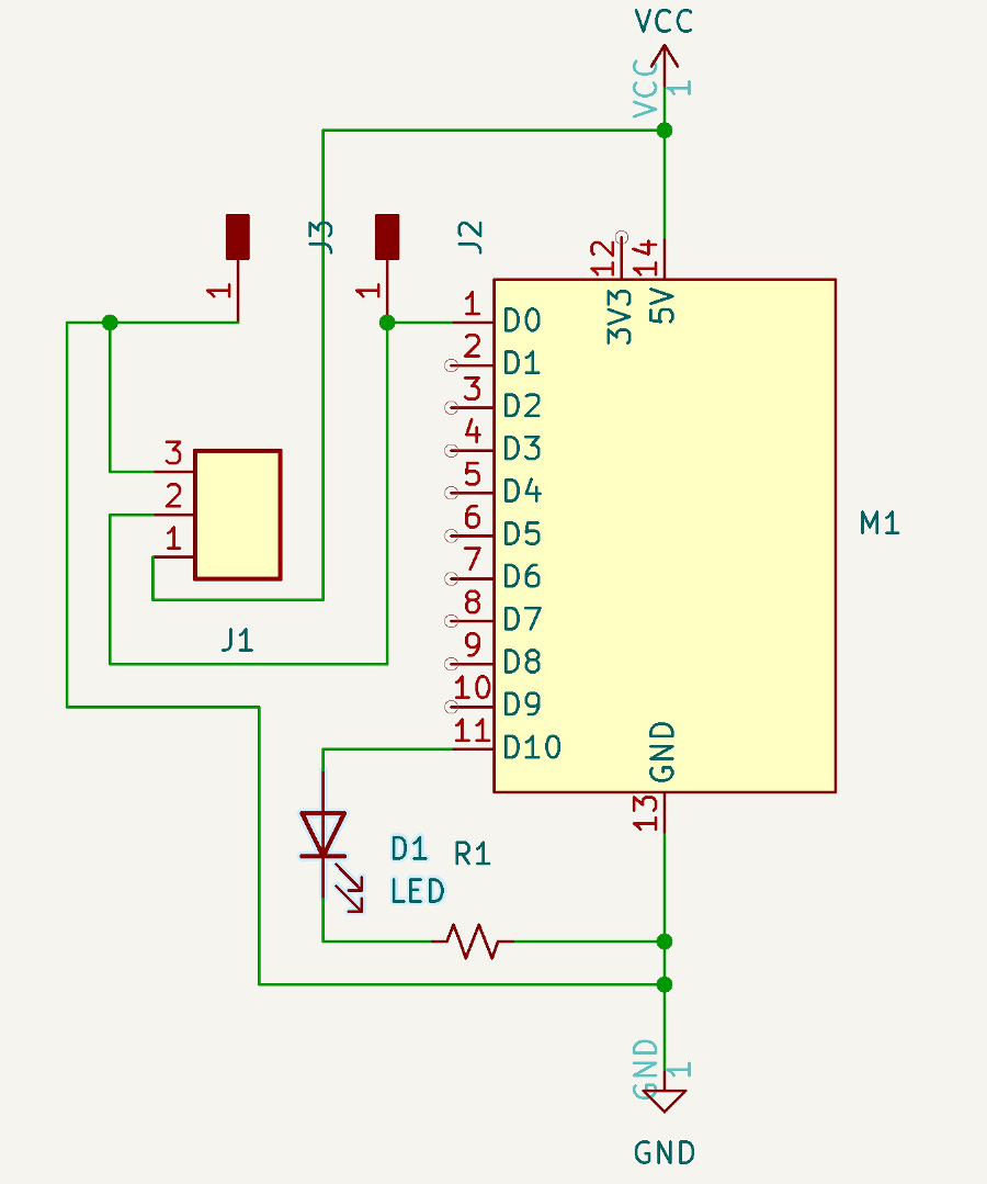
List of components integrated on the PCB:
Overview of the PCB schematic when done:
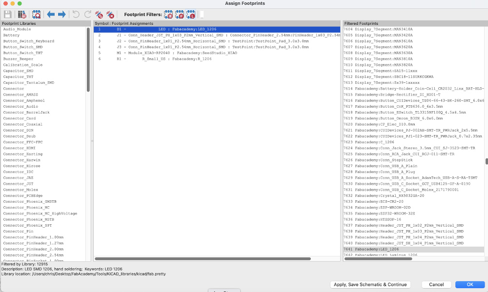
Assignment of the footprints to the components
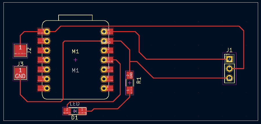
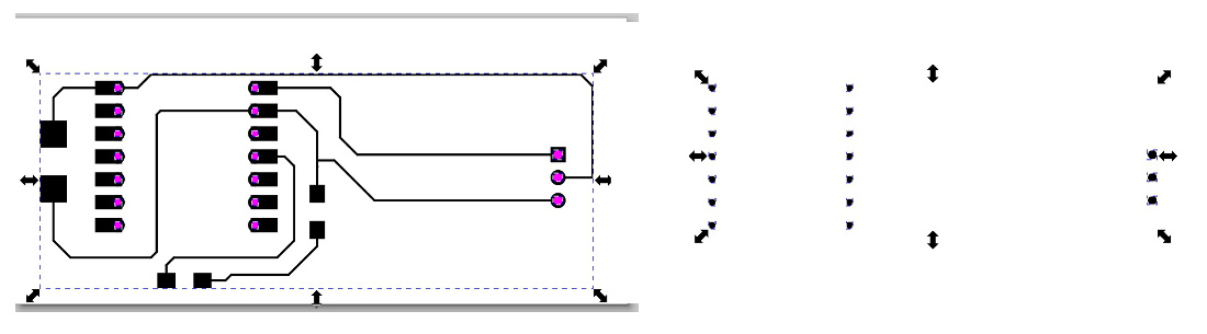
After updating PCB from the schematics, manual move of the components to remove all tracks crosses and routing operations using the "route tracks" button, the results is as follows:
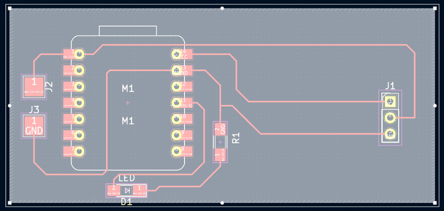
Then I defined and created the edges of the PCB:
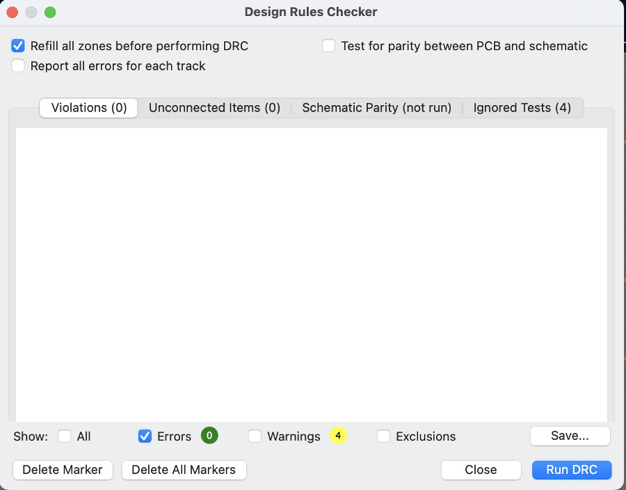
At this stage, I ran a DRC check and no errors came out:
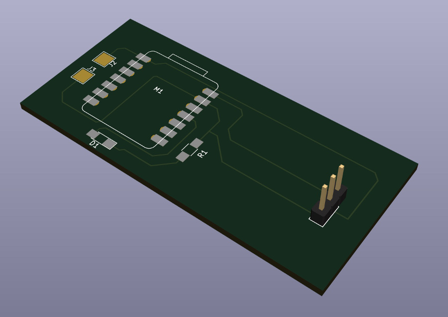
3D view of the newly created PCB:
PCB KiCad file archive download
Export the KiCad project into .svg file(s). Selection of the F.Cu layer, File => export => SVG"

After that I have created an additional .svg file (the holes layer) using INKSCAPE:
.svg files:
Wires layer .svg file Holes layer .svg file Outline layer .svg file
Transformation of the .SVG files into specifc .GCode format using online tool modsproject.org.
Wires layer .rml file Holes layer .rml file Outline layer .rml file
As soon as the 3 .rml files are ready (wires layer, holes layer, outline layer), time to use the Roland SRM-20 milling machine to create the PCB
Overview of the PCB right after completion of the 3 steps milling ((wires layer, holes layer, outline layer)
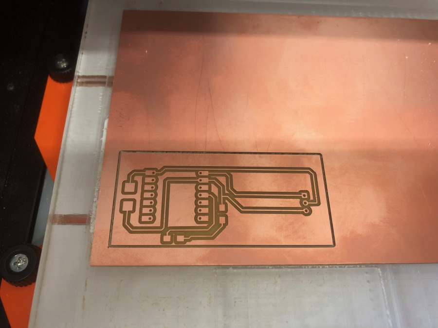
Note: as usal, one 1/64 inch diameter mill has been used to create the wires and one 1/32 inch diameter mill to create to mill the outline and the holes.
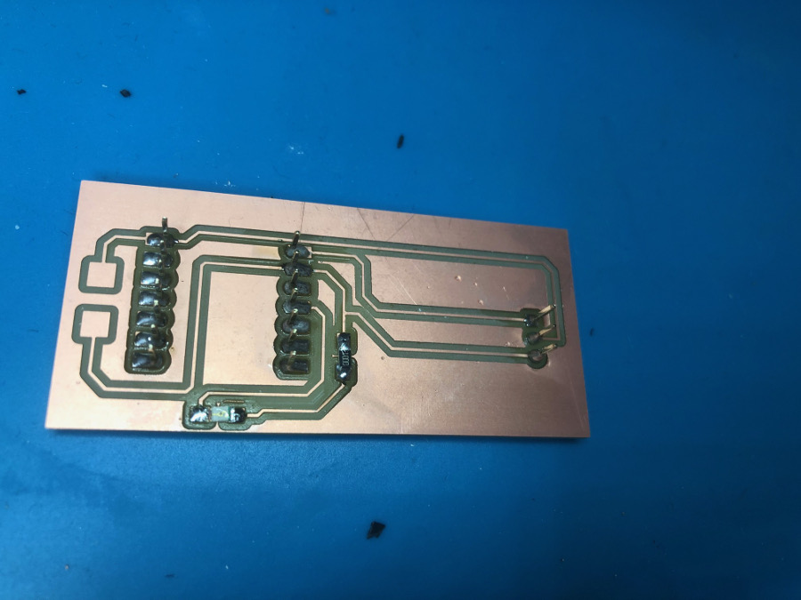
Soldering of the electronic components on the PCB. It took less than 30 minutes (thanks for yhe learning curve )
Module_XIAO-RP2040 mounted on the PCB:
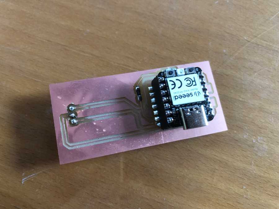
PIR sensor connected to the PCB: the Hardware is ready !
Software programming phase:
Using ARDUINO IDE, I have created a simple piece of code to be uploaded and executed on the XIAO-RP2040:
This piece of code basically deals with:
Overview of the code and execution on the serial monitor:
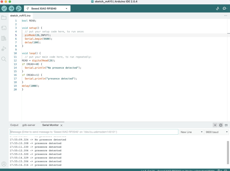
After some testing iteration, we have evidence that the integration of this piece of code with the PIR PCB built works as expected.
ARDUINO Sketch file