For the parts of Laser frame.
Linear guides for movement.
Linear guide holder
Stepper motor
motor holder
Laser_Pointer
The Final Assembly of the Machine
1.Group Assignment.
.design a machine that includes mechanism+actuation+automation+application
. build the mechanical parts and operate it manually
.document the group project and your individual contribution
.actuate and automate your machine
Here you can navigate the Group Page
2.Individual Assignment.
.Document your individual Contribution.
In this week 10,for mechanical design and machine building was really an interesting and educative week we explored more in designing our machine,in fact I was usually get used in designing in the software and it's ended there, but in this week it was not only desiging also it's an implementation which was really difficult for me to some extent because I made some errors and correct them again and I learnt many regarding the implementation.
In our Node we sat and discuss the machine to be designed after sometime we came with 2 machines which are Robotic Arm and Laser cuter machine from the idea of my colleagues.
We spent more time in implementation of the machines.
After agreeing on the machines,we continued in describing the application of the machines and how we can actuate and automate our machines.
Our Robotic Arm is used to pick and press the objects and also Laser cutter machine is used in cutting thin ply wood.
And the discussion of the machines in order to speed up our work we divided ourselves into parts (designing part , implementation and electronic part) and we worked all machines in parallel way so that we may finish them all in the same time.
Me and My colleague Kawayida we were assigned to design machine and supervise the implementation part in order to be relevant to our designs, specifically on my side I had to design Laser cutter.
Firstly We sketched our laser machine and put some dimensions.
After setting the dimensions of the frame of Laser cutter machine, I proceeded with designing it with it's components in Solidworks.
The components We were to use in Laser cutter implementation were; Frame is Ply wood (MDF of 18 mm),linear guide(stainless steel), guide Holders ply wood (MDF 3 mm ),2stepper motor,motor holders,Laser pointer,Brackets(3d Printed).
I take time to design the Laser with this mind that it will be implemented so this pushed me to be keen in dimensioning.
In Solidworks I designed the parts and Assembled it in order to see if it can work.
Below are the parts I designed before Assembling them.
For the parts of Laser frame.
Linear guides for movement.
Linear guide holder
Stepper motor
motor holder
Laser_Pointer
The Final Assembly of the Machine
After Designing the Laser in Software we continued in Printing and cutting the parts we were about to use.
3D Printed Brackets

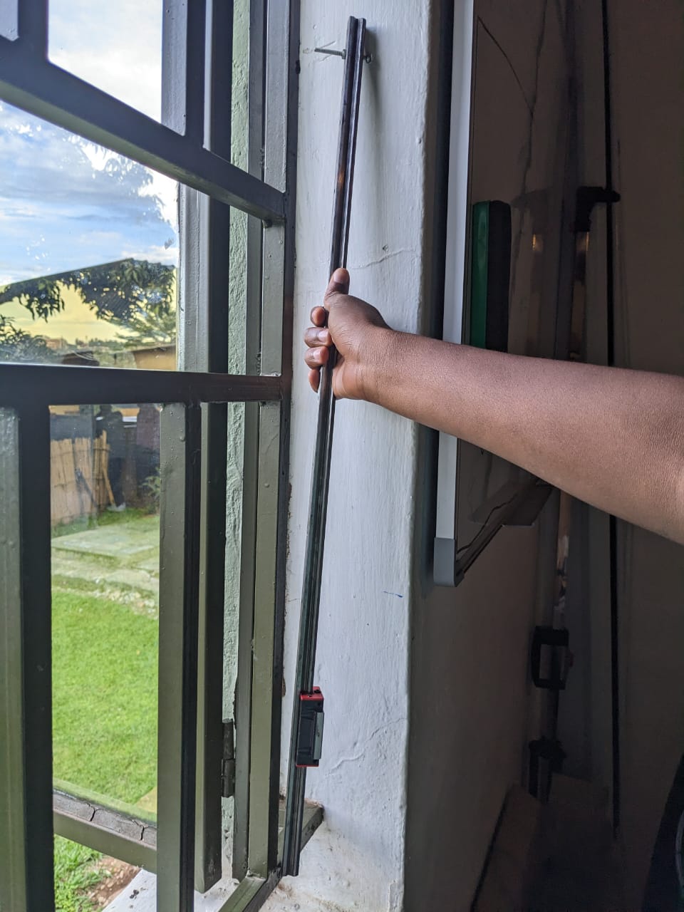
Linear Guide we bought in furniture shop.
Stepper Motor from our workshop

As I was done with the design part of the machine the next step was to save the DXF files in Corel Draw.
After Saving the parts in Solidworks,I Proceeded with saving All frame parts as DXF.
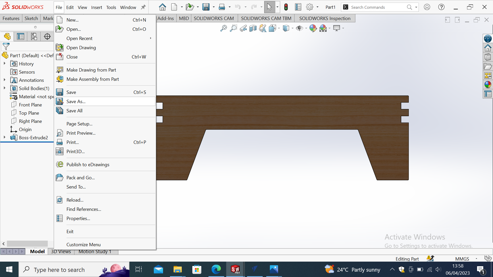
I saved the parts as DXF Files,
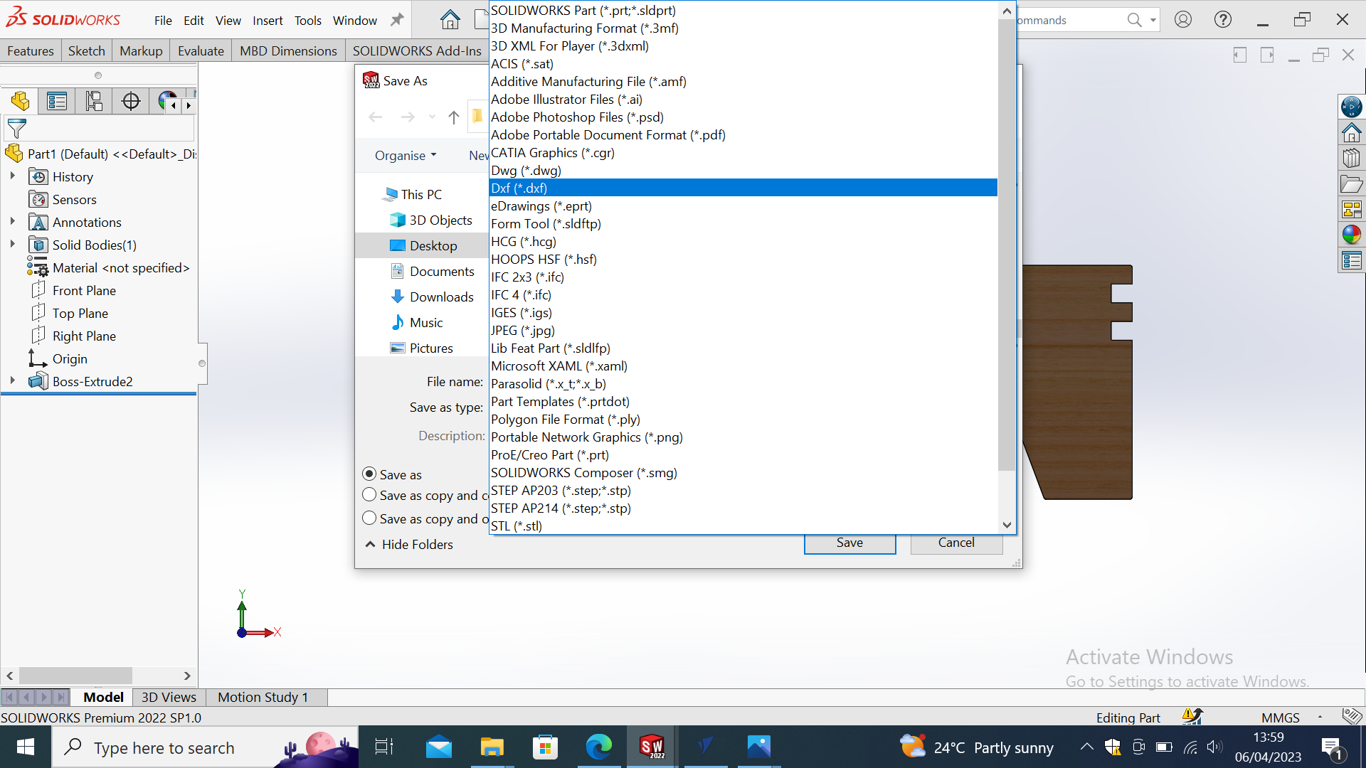
The 2D design to be printed on CNC Machine.
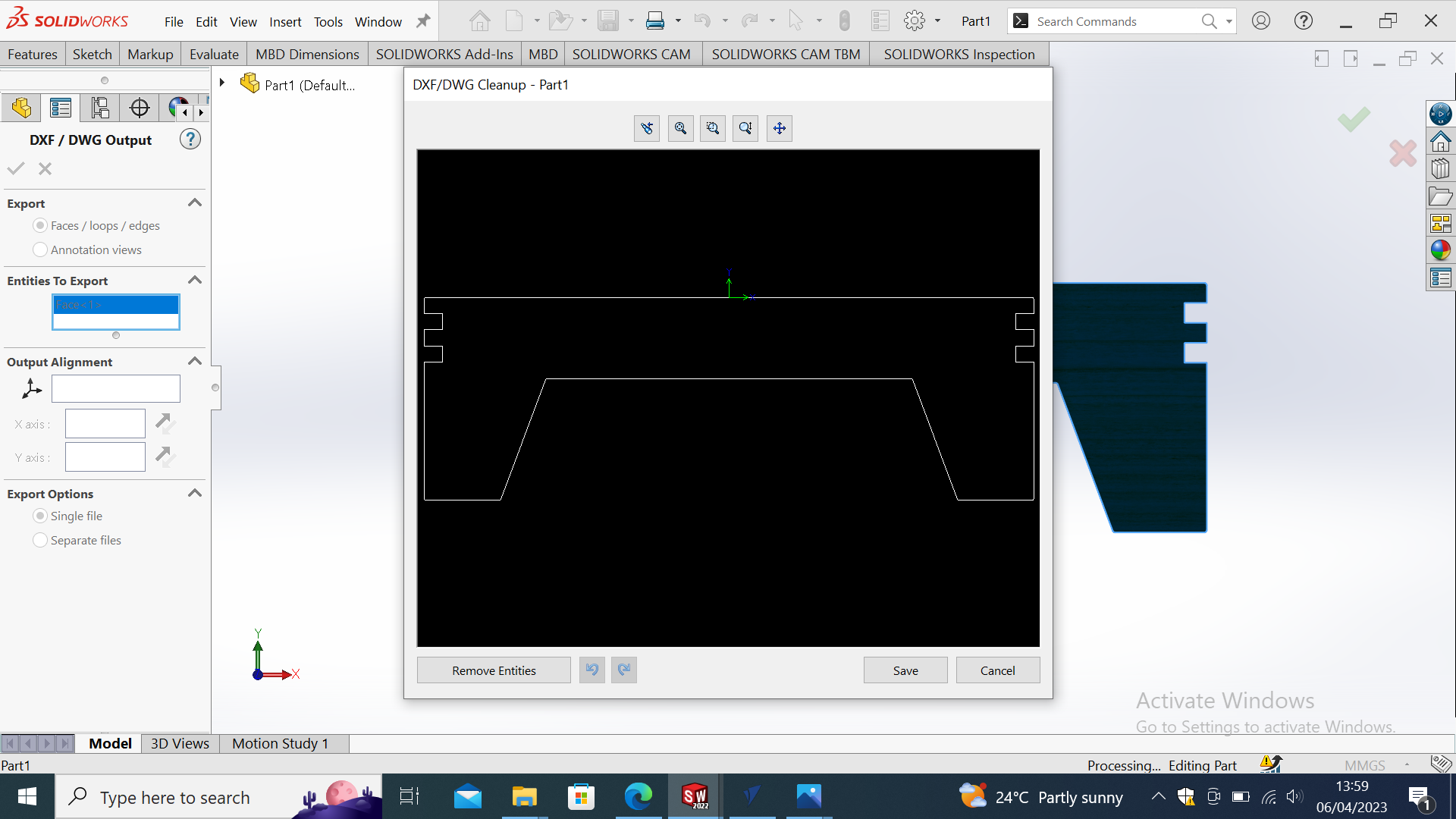
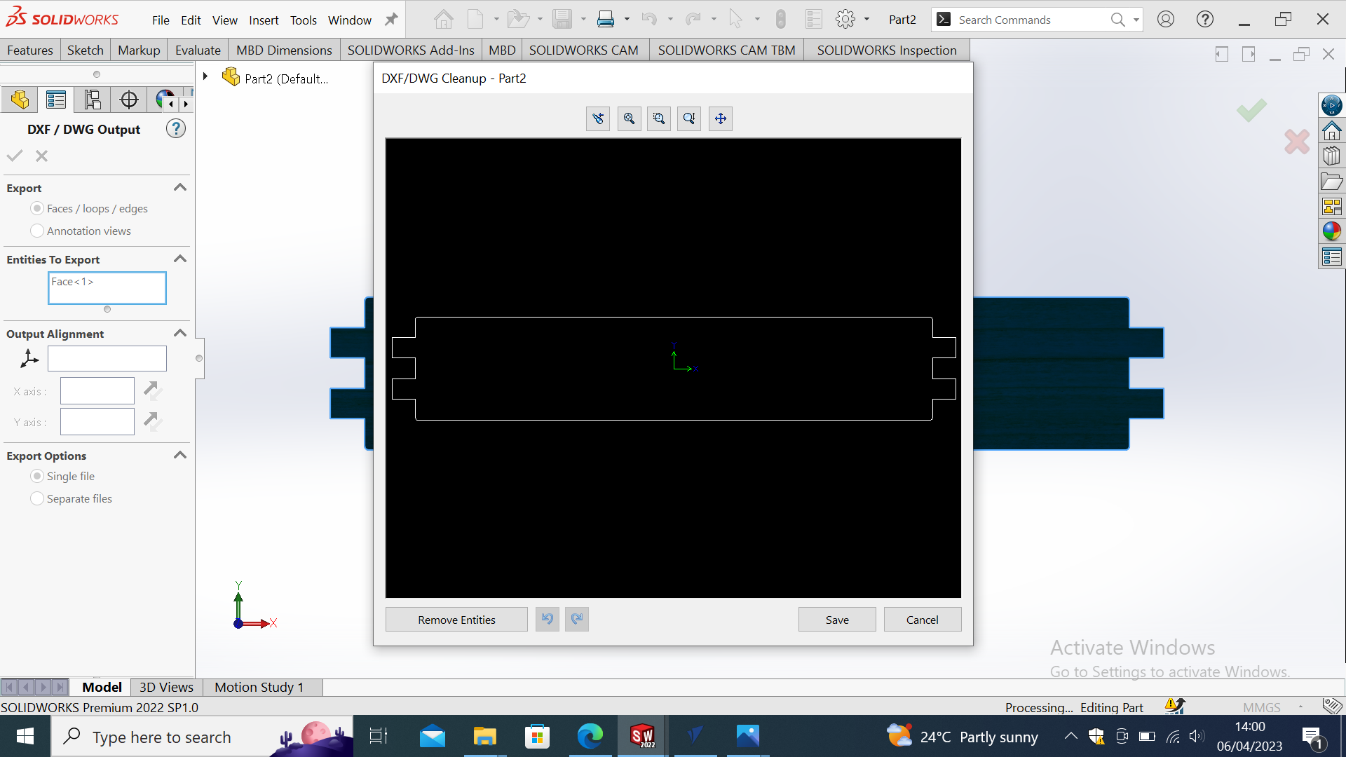
After creating 2D design, I imported the design in VCarve Pro Softwarebelow are the steps I followed.
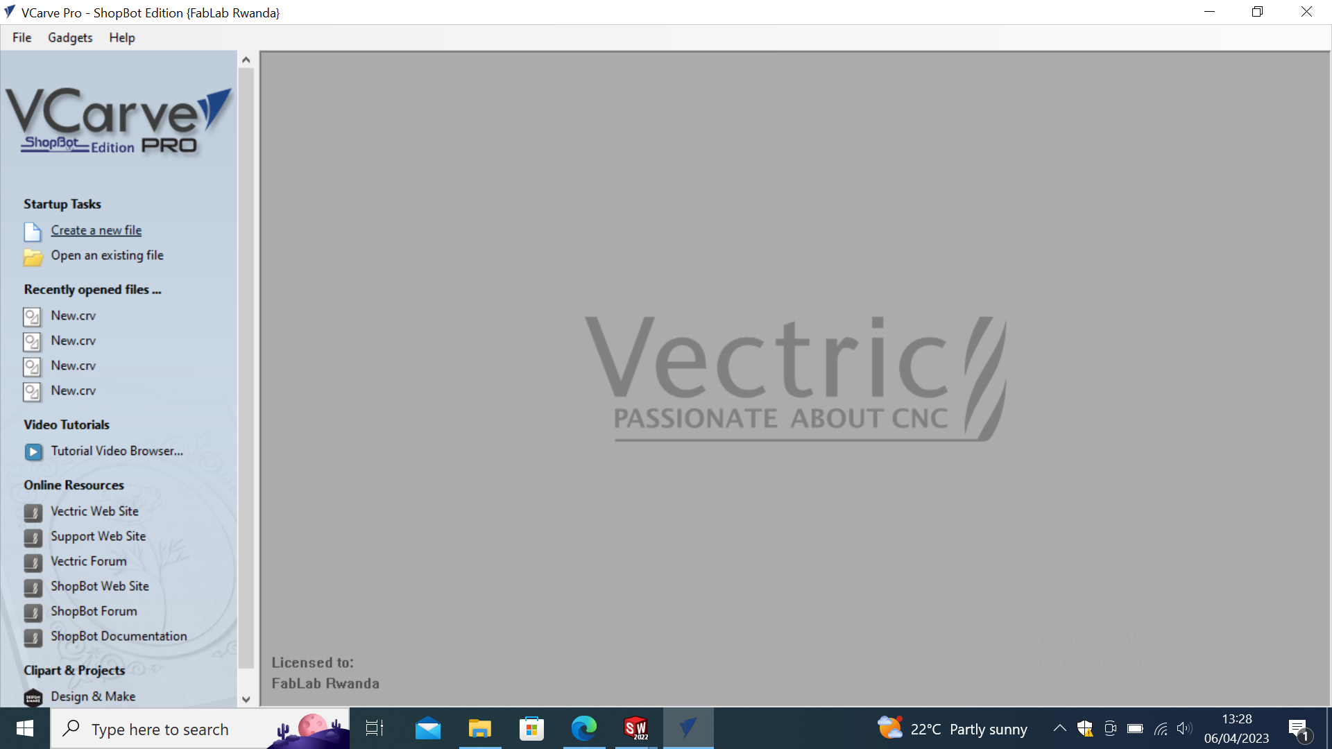
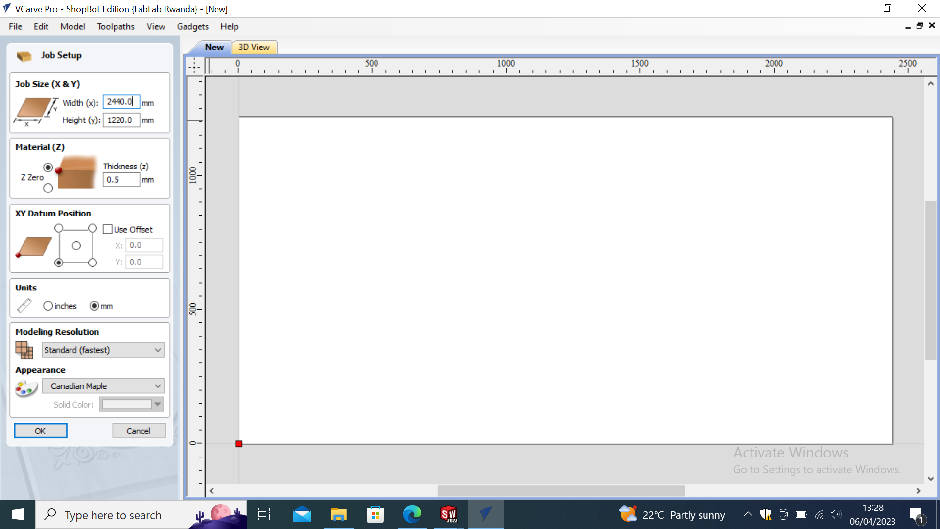
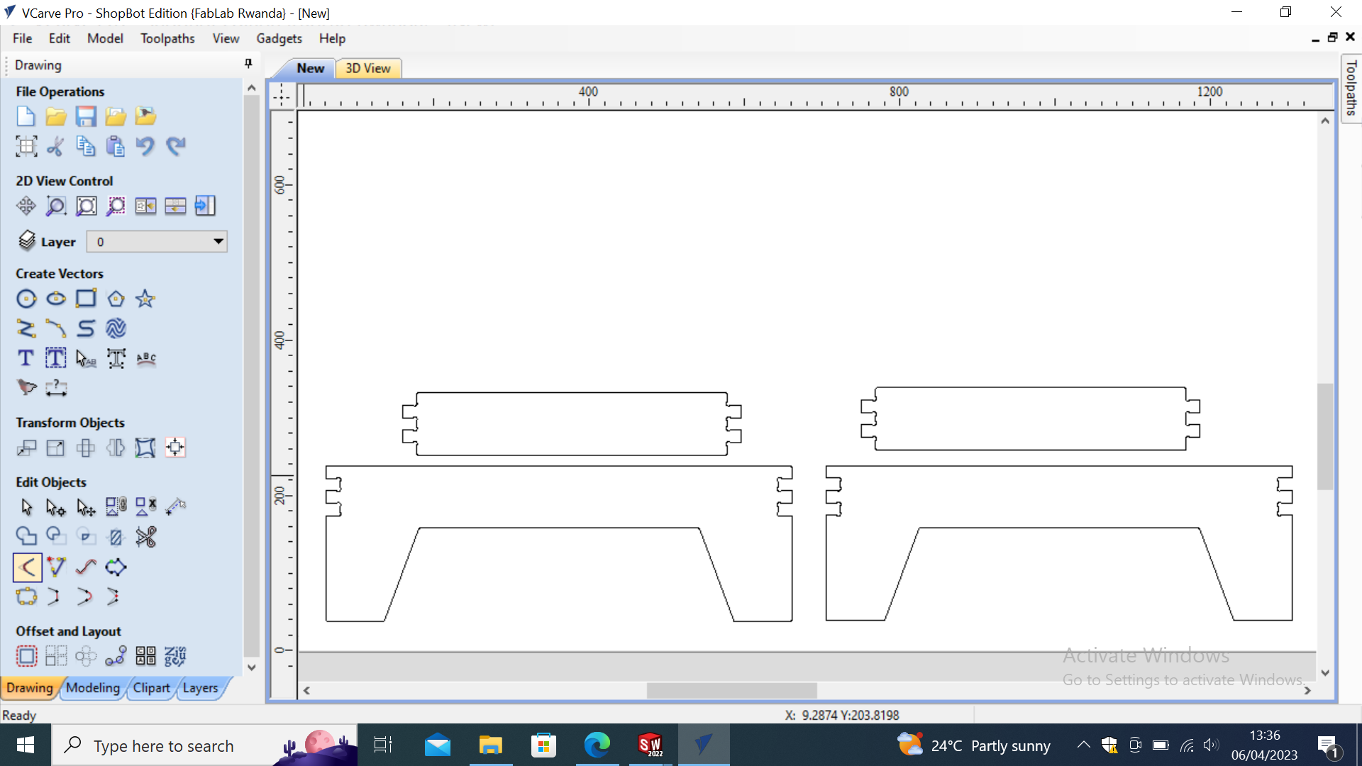

I Followed Same Steps I used in


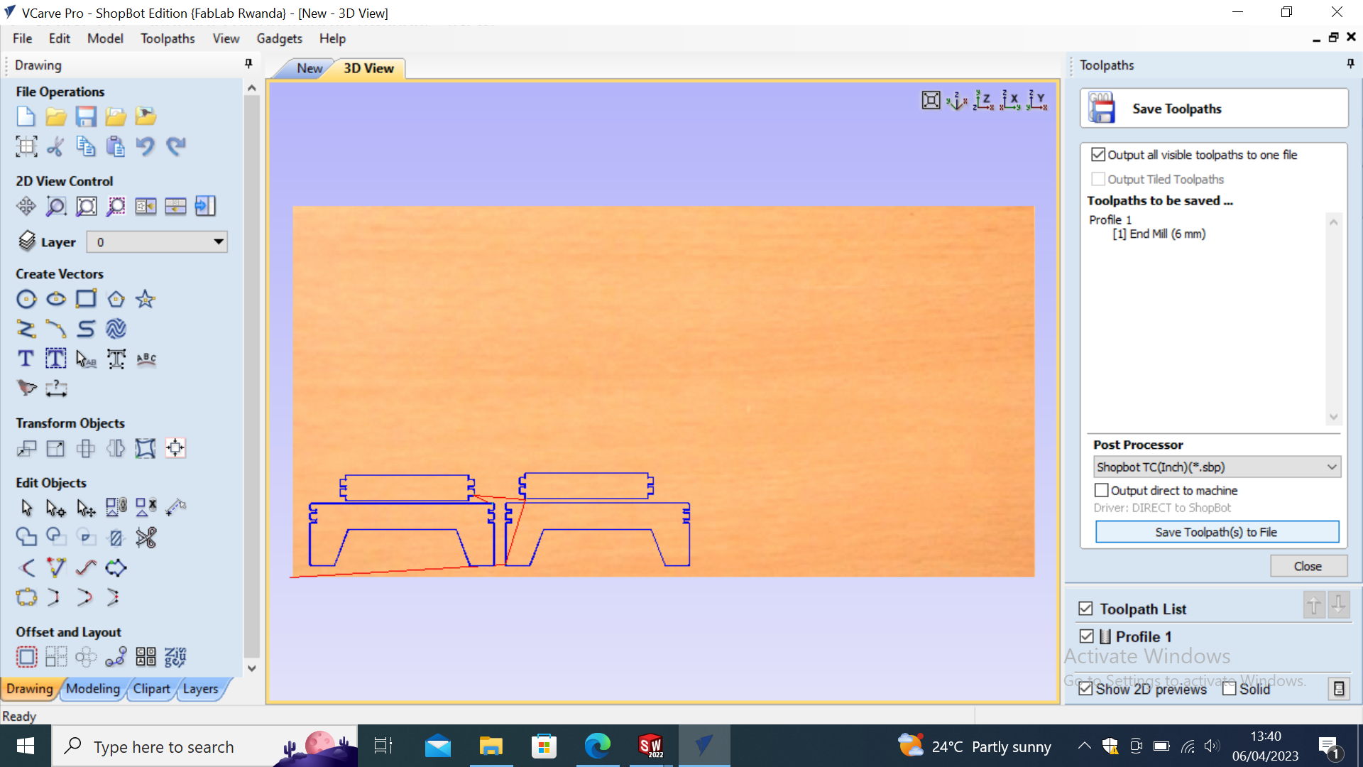

Then After Done With the Vcarve Settings I proceeded with cutting the parts in CNC Shopbot Machine.
Below is Video of CNC cutting the parts.
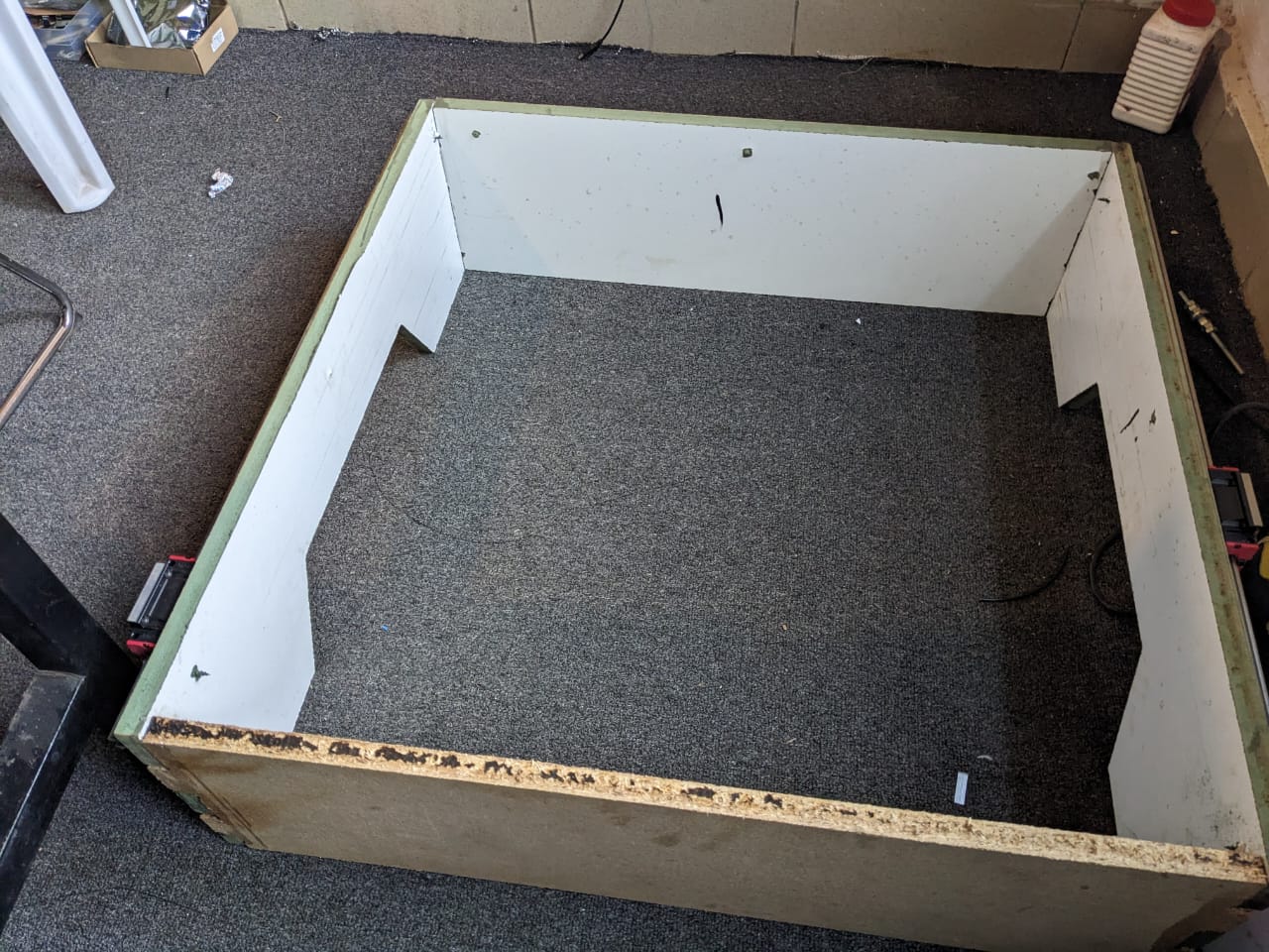
Next Step was to Assemble The parts After Cutting on machine The frame was This below.
Frame of Laser cutted on CNC machine
.jpeg)
.jpeg)
Then After Assembling the our machine parts for mechanical parts the remaining part was the electronics(Control system for our Laser machine), This was played with Other Colleague
So After the sort of many failures and debugging stuffs we did We ended up with Our machine running which was really an Encouragment to us.
Below is the video while Our Laser Engraving.
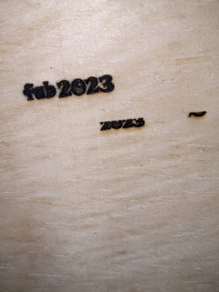
And The Final Output of the workpiece after engraving is below.
