Embedded Programming
Assignment to be done:
1.Group Assignment
Compare the performance and development workflows for other architectures
To be found here
2.Individual Assignment
.
Browse through the data sheet for your microcontroller program a microcontroller development board to interact (with local input &/or output) and communicate (remotely) extra credit: use different languages &/or development environments
1.Group Assignment.
2.Individual Assignment.
Short notes on Embedded Programming and Microcontroller
What is embedded Programming?:
Embedded programming is a specific type of programming that supports the creation of
consumer facing or business facing devices that don't operate on traditional operating systems the way that
full-scale laptop computers and mobile devices do. The idea of embedded programming is part of what drives
the evolution of the digital appliances and equipment in today's IT markets.
Embedded programming is also known as embedded software development or embedded systems programming.
Reference from here
What is Microcontroller?:
A microcontroller is a compact integrated circuit designed to govern a specific operation in an embedded system.
A typical microcontroller includes a processor, memory and input/output (I/O) peripherals on a single chip.
Sometimes referred to as an embedded controller or microcontroller unit (MCU), microcontrollers are found in vehicles,
robots, office machines, medical devices, mobile radio transceivers, vending machines and home appliances, among other devices.
They are essentially simple miniature personal computers (PCs) designed to control small features of a larger component, without a complex front-end operating system (OS).
Reference from here
The first task was to download a Microcontroller IDE from https://www.arduino.cc/en/donate/ by clicking
on JUST DOWNLOAD
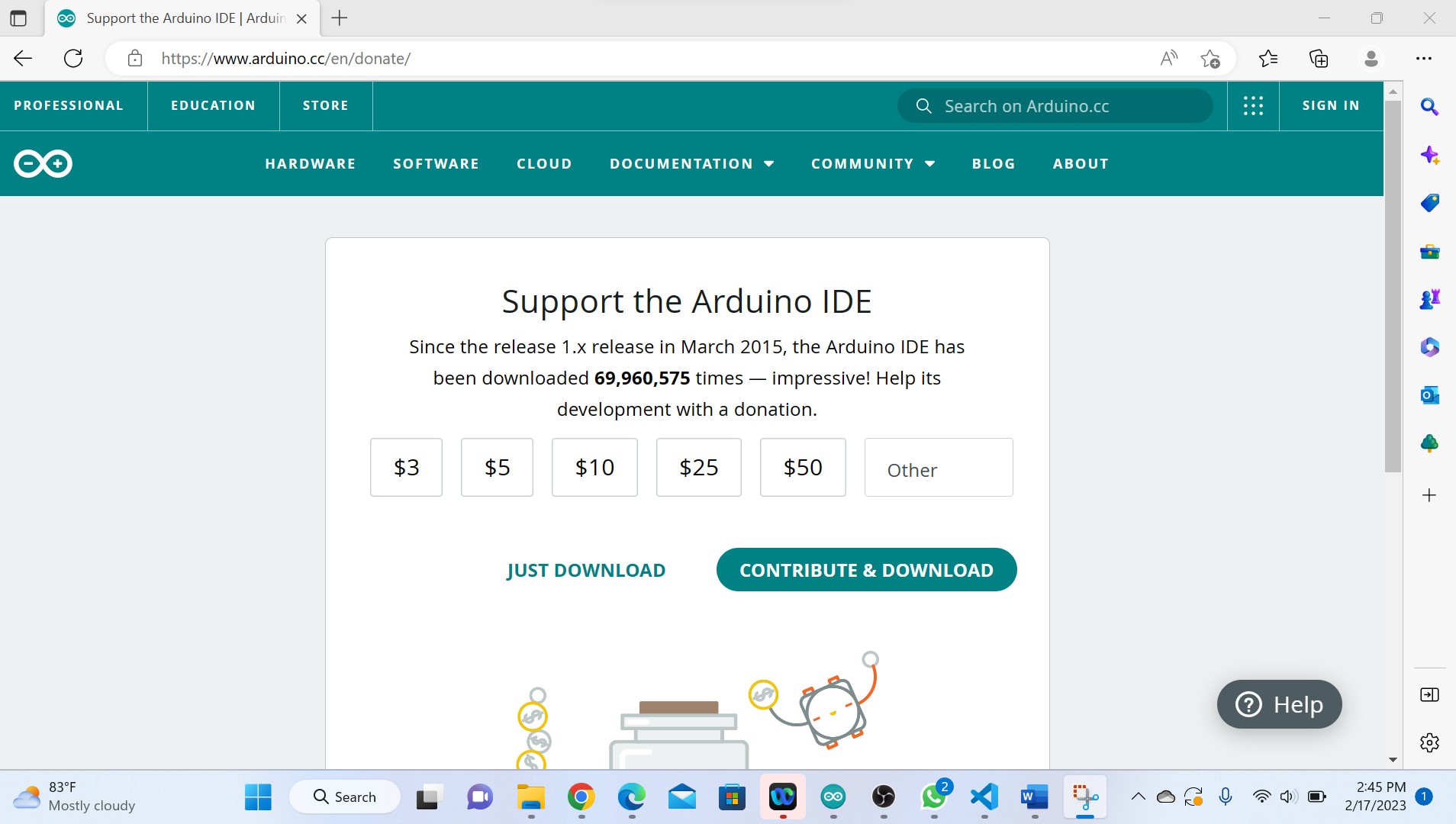
After being dowloaded, it has been installed.
 This figure is of microcontroller IDE opened.
After open it, you check if it can communicate with a computer through its port via tool menu, if you find that its port is not active, you check if its drivers are installed in Device Manager via Computer Management.
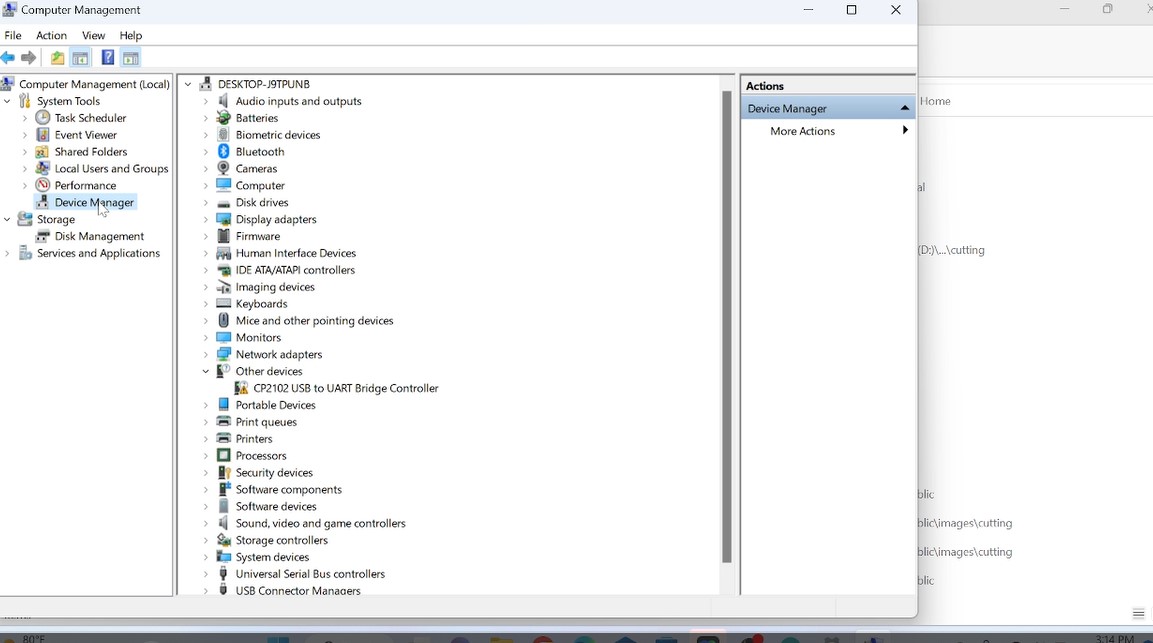 Here is of my case where the drivers were not installed as cp2102 USB is not activated which actually challenged me.
What I did is to download the drivers from https://www.silabs.com/developers/usb-to-uart-bridge-vcp-drivers?tab=downloads
 Here it has been downloaded zipped, I saved it in its folder and unzip it and then back to device manager to install them.
 Here they were installed by browsing their folder where it was saved.
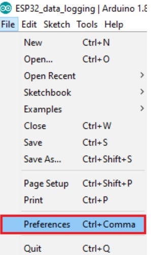
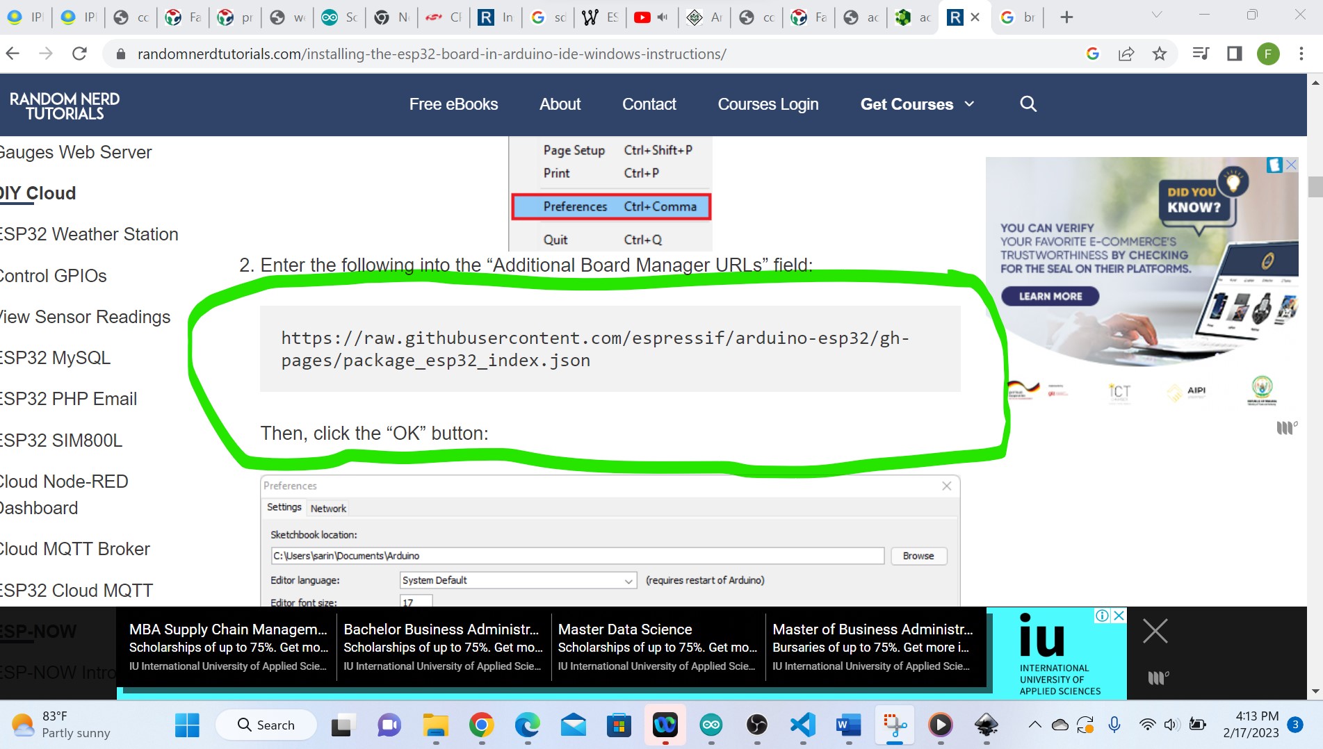
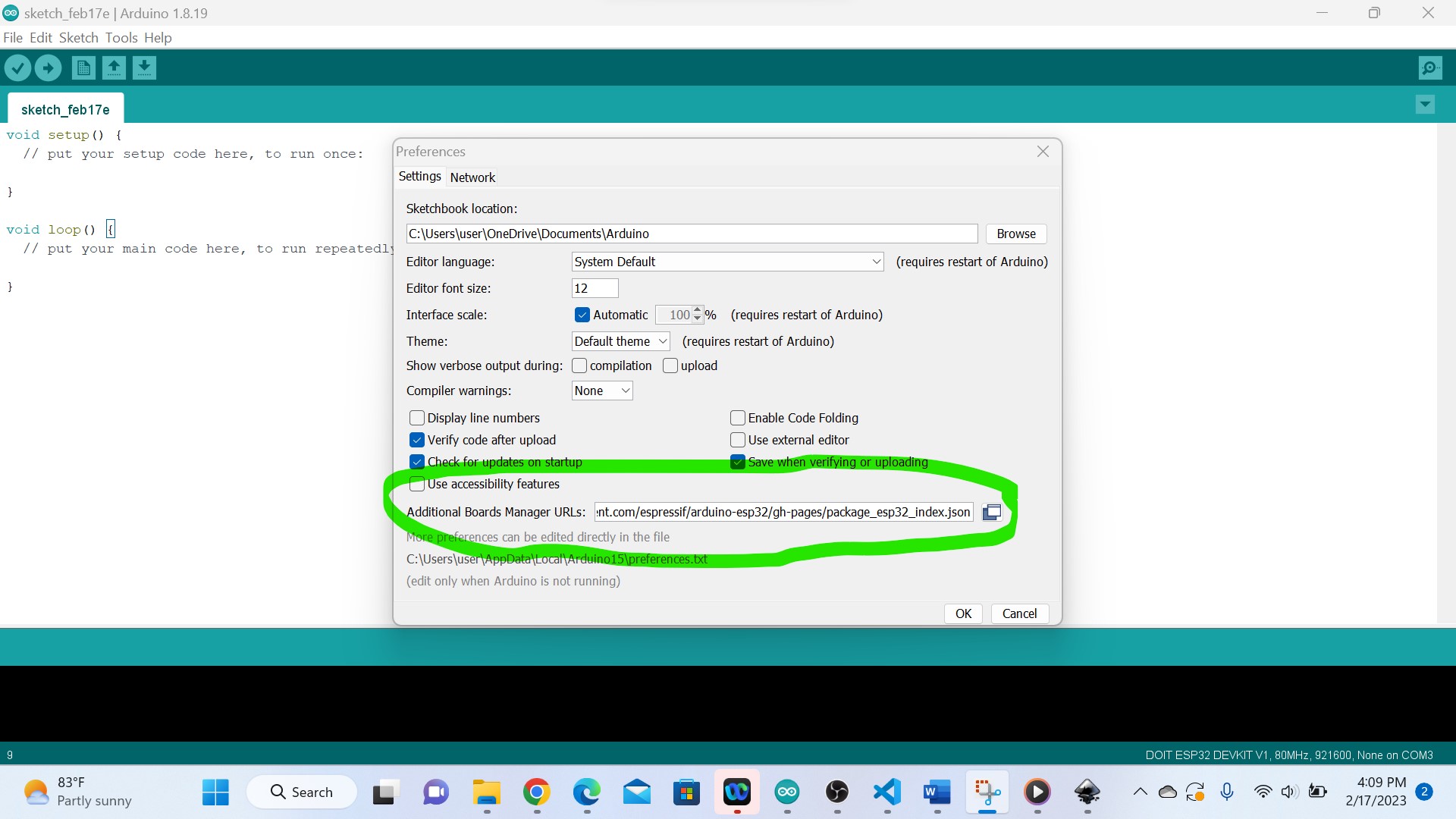
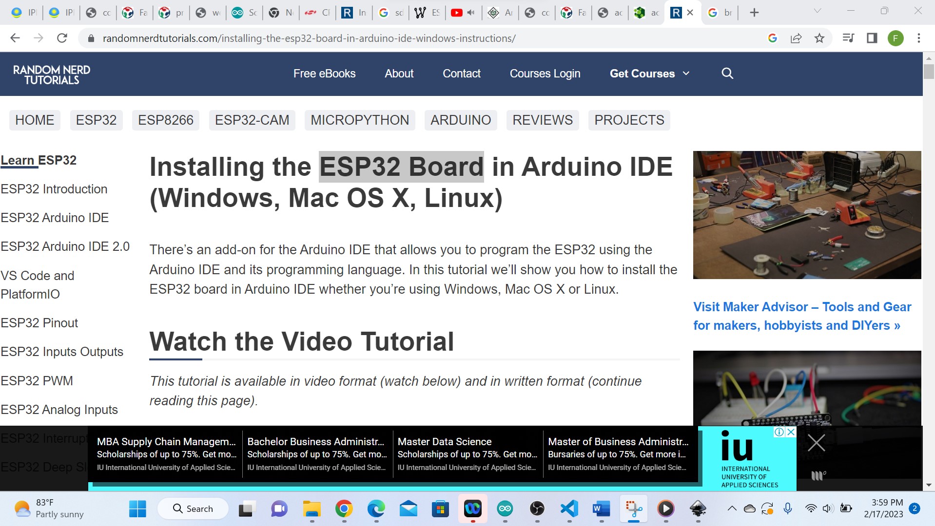 As I was having an ESP32 Board in Lab, the next step was to install it in my arduino IDE by pasting the link from https://randomnerdtutorials.com/installing-the-esp32-board-in-arduino-ide-windows-instructions/ in additional boards manager via file,preferences
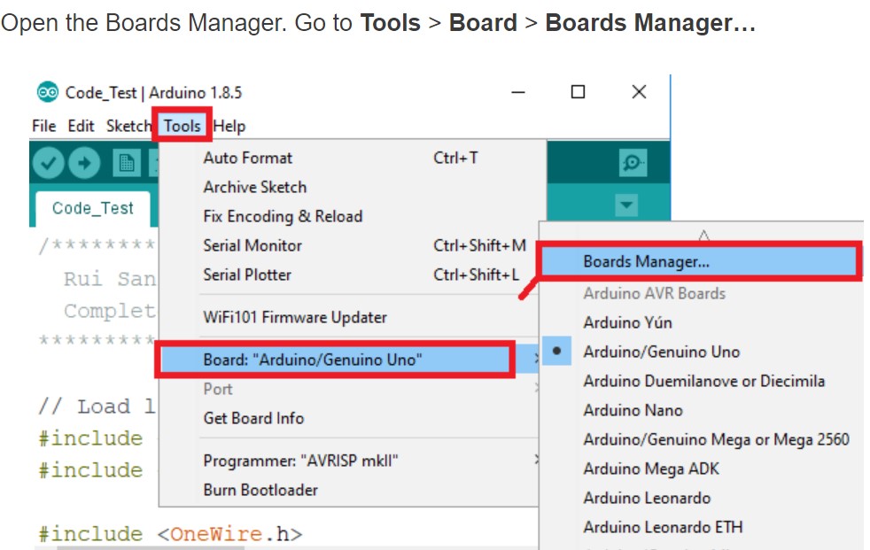 Search for ESP32 and press install button for the “ESP32 by Espressif Systems
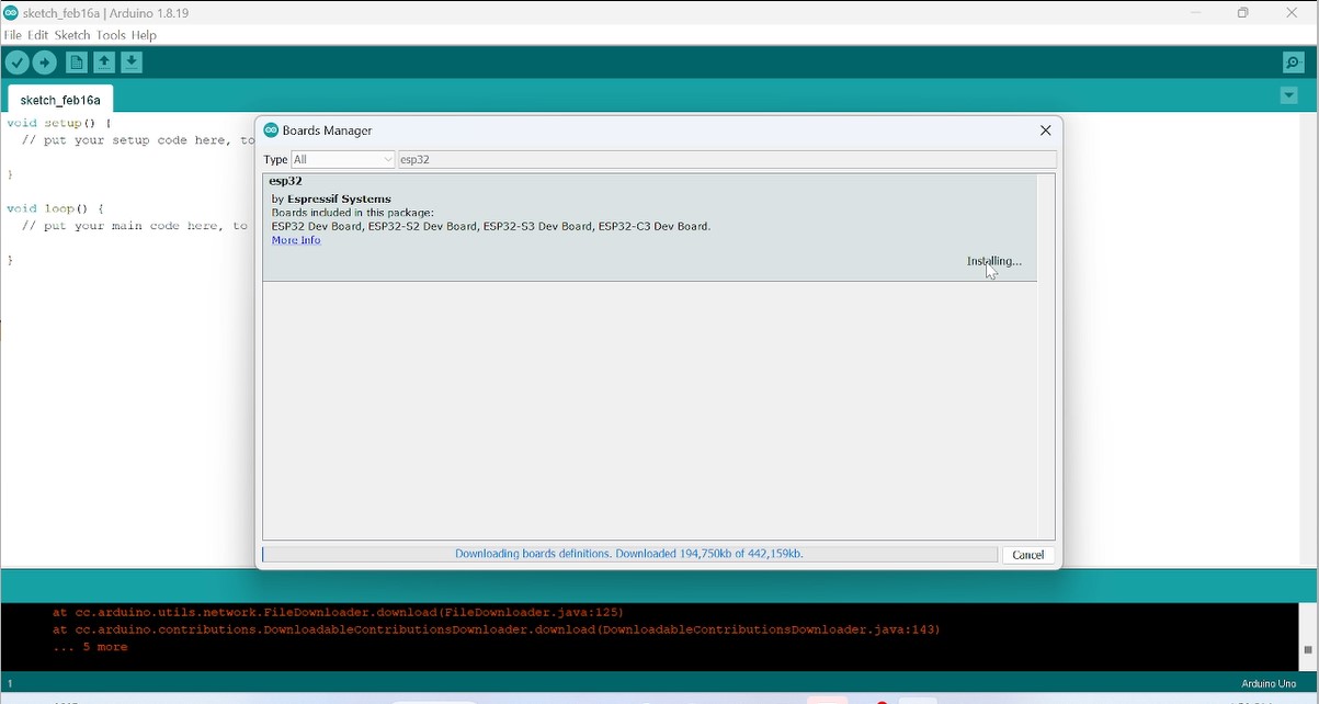 Here I have tried more version as I start from the current and it fails.
When it finished for installation, I juct clicked on close then the whole installation is over and the next is to select it from other many boards as shown in the following screenshot

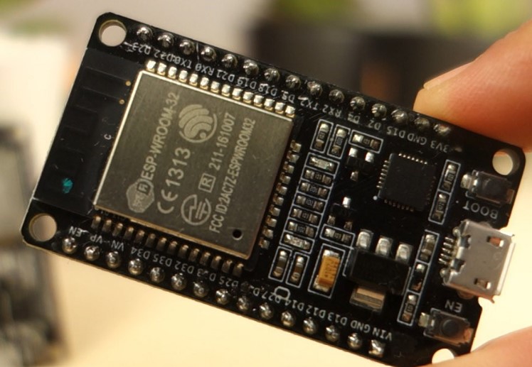
Note tha the used microcontroller is ESP32
Microcontroller is ESP32
According to here(link),ESP32 is the name of the chip that was developed by Espressif Systems. This provides Wi-Fi (and in some models) dual-mode Bluetooth connectivity to embedded devices. While ESP32 is technically just the chip, modules and development boards that contain this chip are often also referred to as “ESP32” by the manufacturer. ESP32 is a series of low-cost, low-power system on a chip microcontrollers with integrated Wi-Fi and dual-mode Bluetooth.
ESP32 Datasheet ESP32 Peripherals
The ESP32 peripherals include:
- 18 Analog-to-Digital Converter (ADC) channels
- 3 SPI interfaces
- 3 UART interfaces
- 2 I2C interfaces
- 16 PWM output channels
- 2 Digital-to-Analog Converters (DAC)
- 2 I2S interfaces
- 10 Capacitive sensing GPIOs
Reference from here
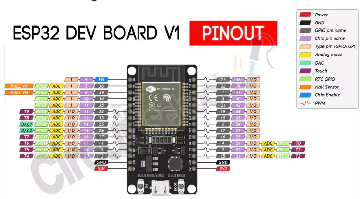
ESP32 Pinout
The ESP32 chip comes with 48 pins with multiple functions. Not all pins are exposed in all ESP32 development boards, and some pins cannot be used.
 For more about the details of ESP32 such as datasheet,its architecture etc, you can refer from here on this link
Additionally, there are pins with specific features that make them suitable or not for a particular project.
The following table shows what pins are best to use as inputs, outputs and which ones you need to be cautious. The pins highlighted in green are OK to use. The ones highlighted in yellow are OK to use, but you need to pay attention because they may have an unexpected behavior mainly at boot. The pins highlighted in red are not recommended to use as inputs or outputs.


 Electrical Characteristics
Absolute Maximum Ratings
Electrical Characteristics
Absolute Maximum Ratings 
Peripherals and Sensors
1. General Purpose Input/Output Interface (GPIO) : The ESP32 microcontroller features a General Purpose Input/Output Interface (GPIO), which provides a flexible and easy way to interface with external devices and circuits. GPIO pins can be used as inputs or outputs, and can be configured to perform a variety of functions depending on the requirements of the system.
2. AnalogtoDigital Converter (ADC) The ESP32 is a microcontroller that features built-in support for an Analog-to-Digital Converter (ADC) module, which allows it to measure analog signals and convert them to digital values that can be processed by the device's processor.
3. DigitaltoAnalog Converter (DAC) : The ESP32 microcontroller also features a built-in Digital-to-Analog Converter (DAC) module, which allows it to generate analog signals from digital values. The DAC module on the ESP32 consists of two channels, which can be used to generate two independent analog signals simultaneously.
4. Universal Asynchronous Receiver Transmitter (UART) : The ESP32 microcontroller features multiple Universal Asynchronous Receiver Transmitter (UART) modules, which provide a simple and flexible way to transmit and receive data between the ESP32 and other devices using only two wires, a transmit line (TX) and a receive line (RX).
5. Serial Peripheral Interface (SPI) : The ESP32 microcontroller features several Serial Peripheral Interface (SPI) modules, which provide a simple and efficient way to communicate with external devices using a synchronous serial protocol.
6. LED PWM: The ESP32 microcontroller includes a Pulse Width Modulation (PWM) module that can be used to generate PWM signals for controlling the brightness of LEDs, the speed of motors, and other applications. The ESP32 PWM module is capable of generating high-resolution PWM signals with up to 16 independent channels. All descrition and datasheet has been refered from here
Programming my board to interact and communicate
In microcontroller programming, it is important to understand the difference between input and output devices in order to correctly program the microcontroller to interact with these devices in the appropriate way.
After going through embedded programming concept and microcontroller in particular,I did some exercises of of programming for some outputs and inputs devices.
In microcontroller programming, input and output devices refer to the ways in which a microcontroller interacts with the external world.
Input device: An input device is a device that provides data or information to the microcontroller. This data could be in the form of sensor readings, user input, or other data that the microcontroller needs to process. Examples of input devices include switches, sensors, and keyboards.
Output device: On the other hand, an output device is a device that receives data or information from the microcontroller. This data could be in the form of instructions to perform a specific action, such as turning on an LED or sending a signal to a motor. Examples of output devices include LEDs, motors, and displays.
The main difference between input and output devices is the direction of the data flow. With input devices, data flows from the external world into the microcontroller, while with output devices, data flows from the microcontroller to the external world. Among exercises I did there is to control a light emetting diode
Exercise1: Blinking(controlling) a LED by using Microcontroller ESP32
By working practically with an electronic component, you need to first study its working principle such as its pins configuration, internal structure etc.
Programming process I used
Overall, programming the output of a microcontroller requires a good understanding of the specific hardware and software platform you are working with, as well as the requirements of the application you are developing. With careful attention to detail and thorough testing, you can develop a program that effectively controls the output of your microcontroller, enabling it to perform a wide range of functions and tasks.
1. Blinking a LED using the ESP32 microcontroller involves the following programming process:
- . As I used ESP32, the first step was to know its pins configuration
- . Open the downloaded arduino IDE where the codes will be developed
- . Initialize the output pin: Next, you need to initialize the output pin that will be used to control the LED. This involves setting the direction of the pin as an output pin using the pinMode function.
- . Write a value to the output pin: Once the output pin is initialized, you can write a value to it using the digitalWrite function to turn the LED on or off
- . Writing a HIGH value to the output pin will turn the LED on, while writing a LOW value will turn it off
- . Add a delay: Depending on the requirements of your application, you may want to add a delay after writing the value to the output pin to ensure that the LED remains on or off for a certain amount of time. This can be done using the delay function, which will pause the program for a specified amount of time.
- . Repeat the process: Finally, the above steps can be repeated in a loop or other iterative process, allowing the LED to be turned on and off in a repeating pattern.
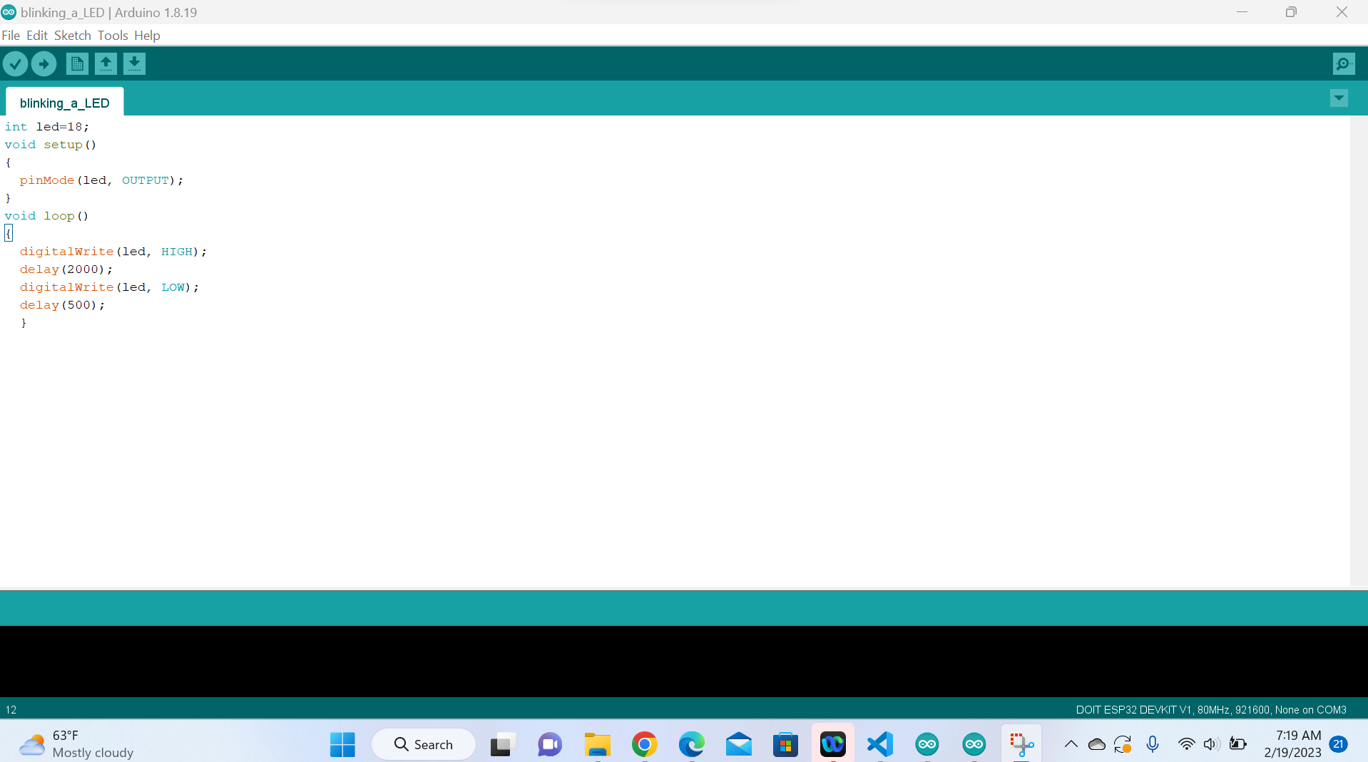
The following are the source codes used:
                                                               int led=18;
                                                               void setup()
                                                               {
                                                                 pinMode(led, OUTPUT);
                                                               }
                                                               void loop()
                                                               {
                                                                 digitalWrite(led, HIGH);
                                                                 delay(2000);
                                                                 digitalWrite(led, LOW);
                                                                 delay(500);
                                                                 }
Hardware implementation
Afeter programming in arduino IDE, you verify by compiling your code, if there are errors you debug them.If no error, you connect your microcontroller board
to your computer through its dedicated USB and upload the codes in its memory.Then after, connect a LED via a protective resistor to limit
the current that can destroy a LED to the chosen
pin of esp32 here is pin18 as it is the one I chose and declared in my codes.
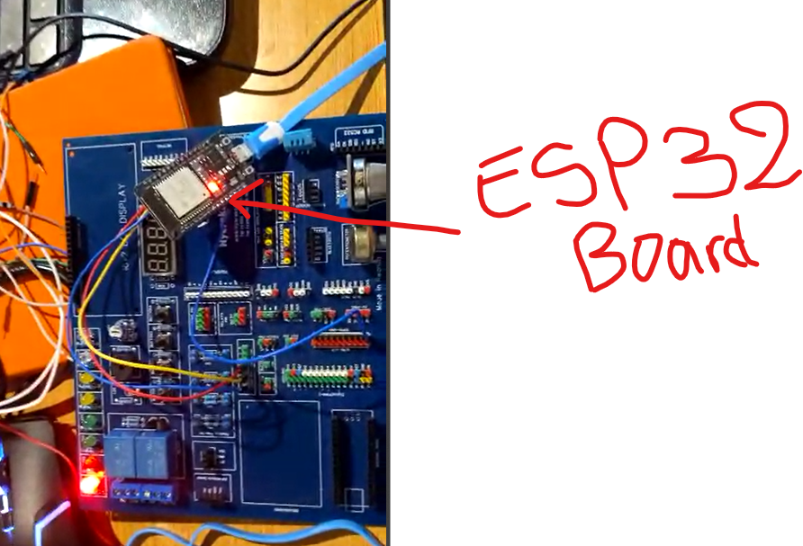
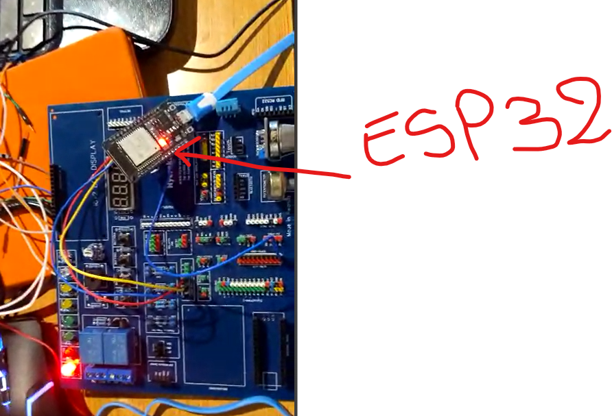
Image above shows hardware implementation of a Blinking a LED using the ESP32 microcontroller
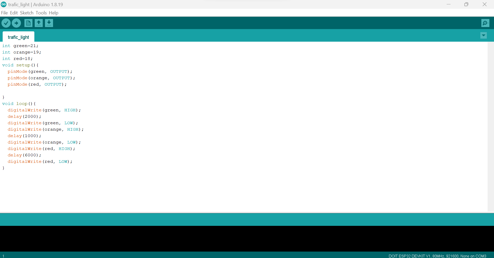
Programming of a Traffic Light using EsP32
Programming a traffic light using ESP32 has been done using the following steps:
- 1. Set up the hardware: Connect the ESP32 board to the traffic light controller circuit, which consists of LEDs and resistors. The LEDs have been used to simulate the traffic lights, and the resistors used to limit the current flowing through them.
- 2. Create a new sketch: Open a new sketch in the IDE.
- 3. Define the pin assignments: Define the pin numbers of the ESP32 that are connected to the traffic light controller circuit.
- 4. Set the pin modes: Set the pin modes to OUTPUT so that the ESP32 can control the LEDs
- 5. Define the traffic light states: Define the different states of the traffic lights as green, yellow, and red and the delay() function to set the duration of each state.
- 6. Write the main program: Write the main program to control the traffic lights
- 7. Test the program: Upload the program to the ESP32 and test it with the traffic light controller circuit. Check that the traffic lights are changing according to the programmed sequence.
The following are the source codes used:
                                                               int green=21;
                                                               int orange=19;
                                                               int red=18;
                                                               void setup(){
                                                               pinMode(green, OUTPUT);
                                                               pinMode(orange, OUTPUT);
                                                               pinMode(red, OUTPUT);

                                                               }
                                                               void loop(){
                                                               digitalWrite(green, HIGH);
                                                               delay(2000);
                                                               digitalWrite(green, LOW);
                                                               digitalWrite(orange, HIGH);
                                                               delay(1000);
                                                               digitalWrite(orange, LOW);
                                                               digitalWrite(red, HIGH);
                                                               delay(6000);
                                                               digitalWrite(red, LOW);
                                                               }
Below video uploaded on youtube is of traffic light using ESP32.
The above works were about programming the outputs devices.
Programming input devices
Programming input devices in a microcontroller is important because it enables the microcontroller to receive and respond
to input signals from various devices such as sensors, switches, and buttons. The input signals can provide valuable
information about the state of the external environment or user interaction, which can be used to control the behavior of the microcontroller and perform various tasks.
They are many reasons why programming input devices in a microcontroller is important such as:
Sensing and measurement: Many microcontroller-based systems use sensors to measure physical parameters such as temperature,
pressure, and light intensity. The microcontroller can read the sensor data and use it to control other parts of the system, such as turning on a fan to cool down a device if the temperature is too high.
User interaction: Microcontrollers are often used in devices that require user input, such as remote controls, game controllers, and keypads. The microcontroller can read the user input and perform the appropriate action, such as changing the channel on a TV or moving a character in a game.
Automation and control: Microcontrollers are widely used in industrial and automation systems to control various processes and machines. Inputs from sensors and switches can be used to monitor the state of the system and adjust the control parameters accordingly.
Security and safety: Input devices can also be used for security and safety purposes. For example, a microcontroller-based security system can use inputs from sensors and switches to detect intrusion or fire and trigger an alarm or activate a sprinkler system.
In summary, programming input devices in a microcontroller is essential for enabling the microcontroller to interact with the external environment, perform various tasks, and ensure the safety and security of the system.
Steps for Programming a push button using EsP32 to control a LED:
- Connect the push button and LED to the ESP32 board: Connect one pin of the push button to a digital pin of the ESP32 and the other pin to the ground pin of the ESP32.
- Connect one pin of the LED to another digital pin of the ESP32 and the other pin to a resistor and then to the ground pin of the ESP32.
- Create a new sketch: Open a new sketch in the IDE and give it a suitable name.
- Define the pin assignments: Define the pin numbers of the ESP32 that are connected to the push button and LED.
- Set the pin modes: Set the pin modes to INPUT_PULLUP for the push button and OUTPUT for the LED.
- Write the main program: Write the main program to read the state of the push button using the digitalRead() function. If the button is pressed, turn on the LED using the digitalWrite() function. If the button is not pressed, turn off the LED.
Here are source codes for programming a push button using ESP32 to control a LED:
                                                                  int led = 19;
                                                                  int button = 18;
                                                                  int button_bit;
                                                                  void setup() {
                                                                  Serial.begin(9600);
                                                                  pinMode(led,OUTPUT);
                                                                  pinMode(button,INPUT);

                                                                  }

                                                                  void loop() {
                                                                   button_bit=digitalRead(button);
                                                                   Serial.print(button_bit);
                                                                   delay(100);
                                                                   if(button_bit ==1)
                                                                   {
                                                                  digitalWrite(led, HIGH);
                                                                   }
                                                                   else
                                                                   {
                                                                  digitalWrite(led, LOW);
                                                                   }
                                                                   }

Image below shows hardware implementation of a push button to control a LED using EsP32 microcontroller
Control of LEDS Via Bluetooth by using EsP32
Steps:
- 1. Set up the hardware: Connect the LEDs to the appropriate pins(here I used pin 19 and GND) on the ESP32 board. Connect a Bluetooth module to the ESP32 board(here for esp32 Bluetooth is embedded).
- 2. Initialize the Bluetooth module: Use the BluetoothSerial library to initialize the Bluetooth module and set the device name and PIN code for pairing.
- 3. Initialize the LEDs: Use the pinMode() function to set the LED pins as outputs in the setup() function(here is pin 19).
- 4. Set up the loop() function: Use the Serial.available() function to check for incoming data from the Bluetooth module. If data is available, read it and convert it to an integer value using the Serial.parseInt() function.
- 5. Control the LEDs: Use the digitalWrite() function to set the LED pins HIGH or LOW based on the incoming integer value.
- 6. Upload the code: Compile and upload the code to the ESP32 board using the Arduino IDE.
- 7. Download a serial Bluetooth terminal app on smartphone
- 8. Pair the devices: Pair your mobile device with the ESP32 board using the device name
- 9. Control the LEDs: Use a Bluetooth terminal app on your mobile device to send integer values to the ESP32 board. The board will receive the values and use them to turn the LEDs on or off.
      #include "BluetoothSerial.h"
#if !defined(CONFIG_BT_ENABLED) || !defined(CONFIG_BLUEDROID_ENABLED)
#error Bluetooth is not enabled! Please run `make menuconfig` to and enable it
#endif
byte light;
BluetoothSerial SerialBT;

    void setup() {
     Serial.begin(115200);
     SerialBT.begin("espCHRIS"); //Bluetooth device name
     Serial.println("The device started, now you can pair it with bluetooth!");
     pinMode(19, OUTPUT);
                }

        void loop() {
       if (SerialBT.available()) {
       light = SerialBT.read();
        delay(20);
           }

      if (light == '1'){
      digitalWrite(19, HIGH);
              }
        else if (light == '0'){
        digitalWrite(19, LOW);
                                         }

                                        }
Below video uploaded on youtube is of controlling LEDs trough bluetooth using ESP32 . NAVIGATION
USEFUL LINKS FOR MORE KNOWLEDGE
https://randomnerdtutorials.com/ https://www.w3schools.com/java/java_intro.asp https://www.w3schools.com/html/default.asp https://developer.mozilla.org/en-US/docs/Web/HTML/Element/brAddress
2023 All Rights Reserved. Designed by Felix NYIRIGIRA