Week 11: Input Devices
Input Devices
Assignment activities: Group assignment: Probe an input device's analog levels and digital signals Individual assignment: Measure something: add a sensor to a microcontroller board that you have designed and read ItI.Group Assignment:
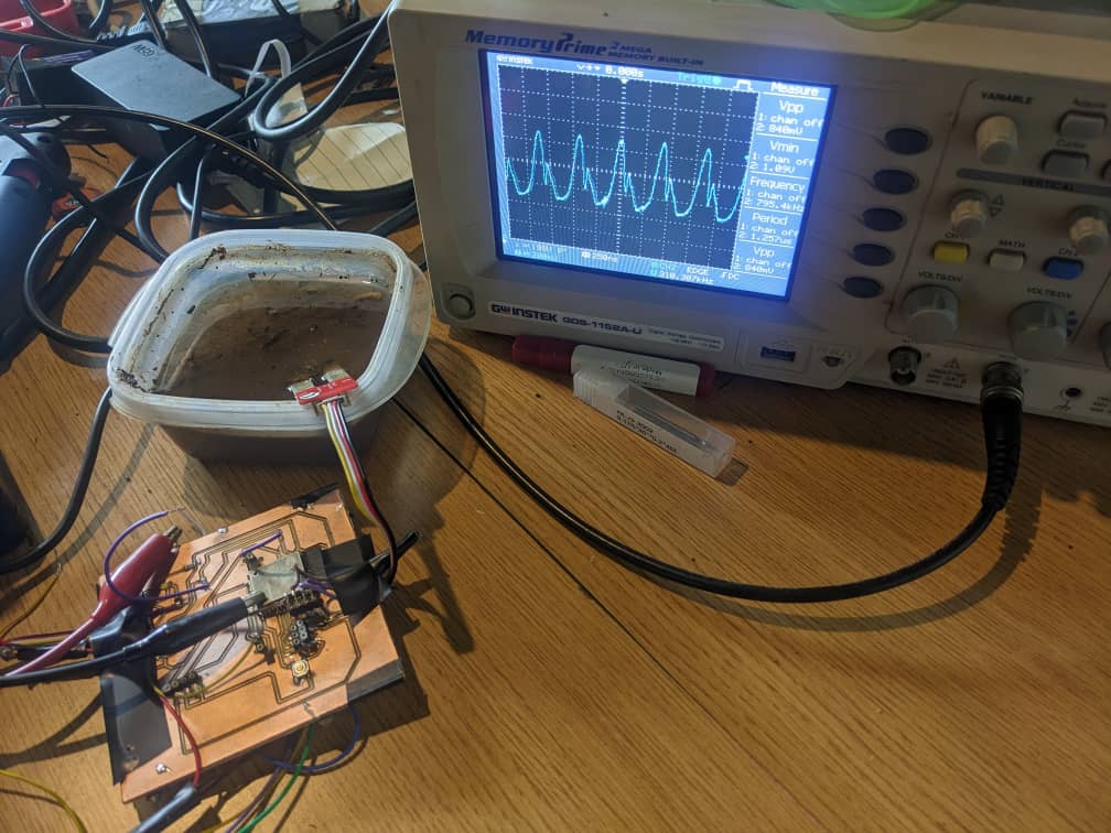
Probe an input device's analog levels and digital signals If you want to explore the group Assignment Click Here In group assignment we probe a moisture sensor as the input device and measure its output voltage using a multimeter and visualize the signal on an oscilloscope Gather the necessary equipment: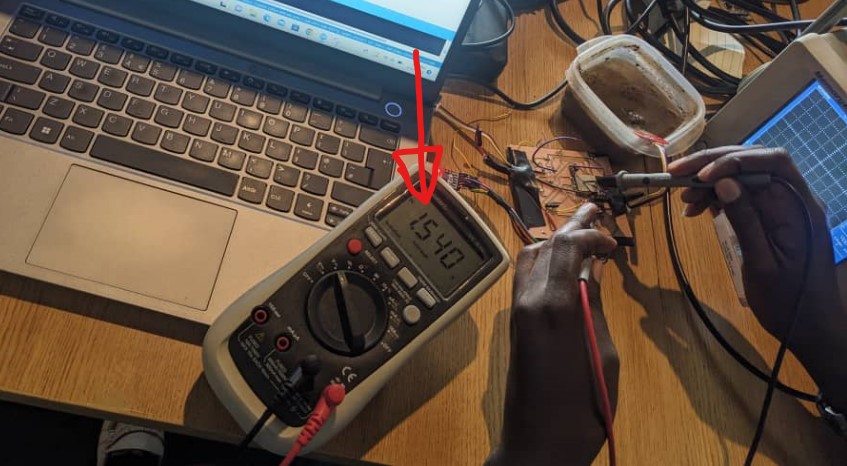
II.Individual assignment:
In this Assignment we will use DHT11 Sensor for measuring Temperature and Humidity. 1. DHT11 Temperature and Umidity Sensor The DHT11 is a digital temperature and humidity sensor that uses a capacitive humidity sensor and a thermistor to measure the surrounding air. It provides reliable readings of temperature ranging from 0 to 50°C with an accuracy of ±2°C and relative humidity ranging from 20 to 80% RH with an accuracy of ±5%. The sensor is connected via a single-wire serial interface and can be easily interfaced with most microcontrollers. Click Here for Reference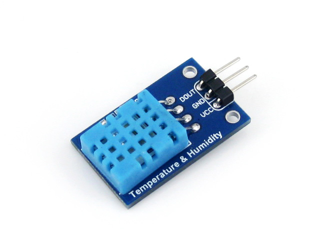 1. Datasheet for DHT11 Temperature and Umidity Sensor
- 2. Operating voltage: 3V to 5.5V DC
- 2. Current Consumption: 2.5mA max
- 3. Humidity measurement range: 20% to 90% RH
- 4. Temperature measurement range: 0°C to 50°C
- 5. Accuracy: ±5% RH, ±2°C
- 6. Sampling rate: once every 2 seconds
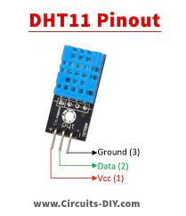
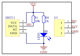 2. Pin Description for DHT11 Temperature and Umidity Sensor
- 2. Pin 1: VCC: Power supply (3.3V to 5.5V)
- 2. Pin 2: Data: Serial data output
- 3. Pin 3: NC: Not connected
- 4. Pin 4: GND: Ground
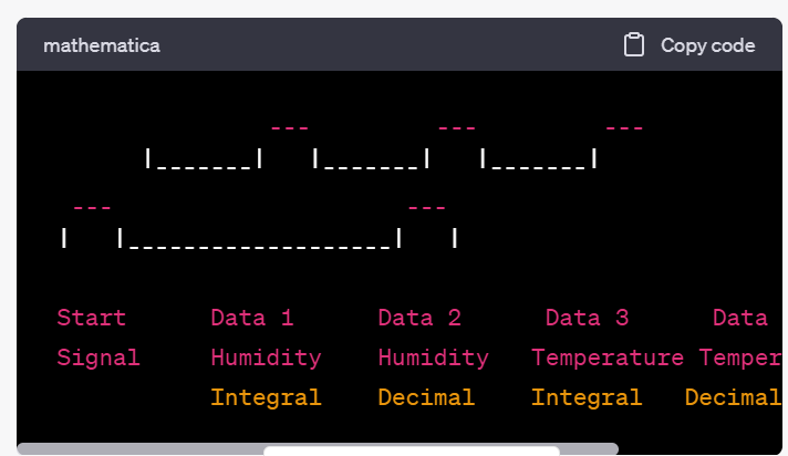
 3. Timing Diagram for DHT11 Temperature and Umidity Sensor
The sensor transmits data by encoding it in 40 bits with a specific timing sequence. The following is the timing diagram for the DHT11 sensor, Note: Each bit is transmitted as a 50us low followed by either a 26-28us high (0) or a 70us high (1).
3. Timing Diagram for DHT11 Temperature and Umidity Sensor
The sensor transmits data by encoding it in 40 bits with a specific timing sequence. The following is the timing diagram for the DHT11 sensor, Note: Each bit is transmitted as a 50us low followed by either a 26-28us high (0) or a 70us high (1).
 By using a microcontroller board that you have designed in Week 9 Output_Devices We use DHT11 Temperature and Umidity Sensor as Input Device for measuring Temperature and Humidity and we use also ESP23 Microcontroller, ESP23 Datasheet
Here is Schematic Used
By using a microcontroller board that you have designed in Week 9 Output_Devices We use DHT11 Temperature and Umidity Sensor as Input Device for measuring Temperature and Humidity and we use also ESP23 Microcontroller, ESP23 Datasheet
Here is Schematic Used
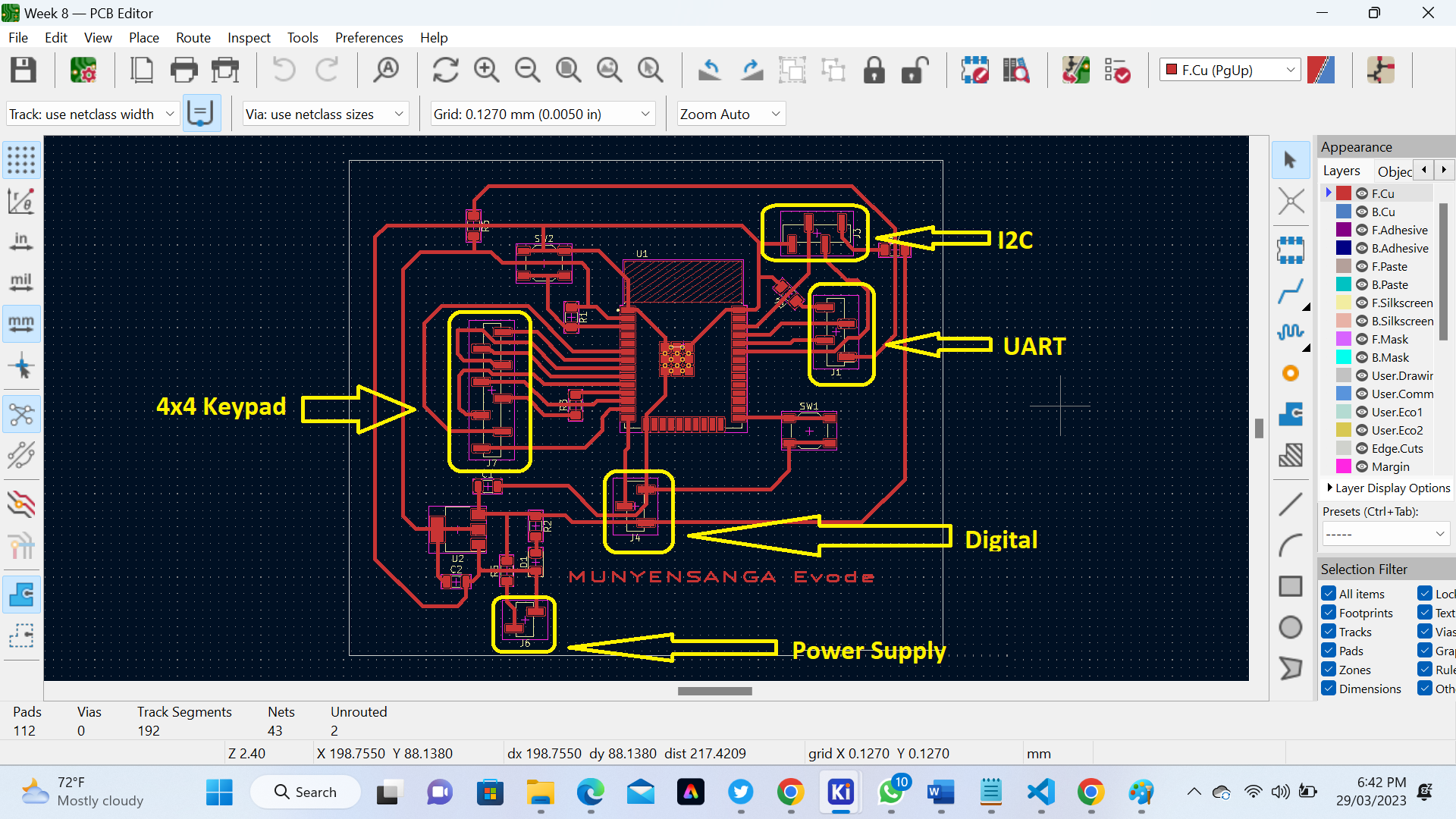
 Here is PCB Used
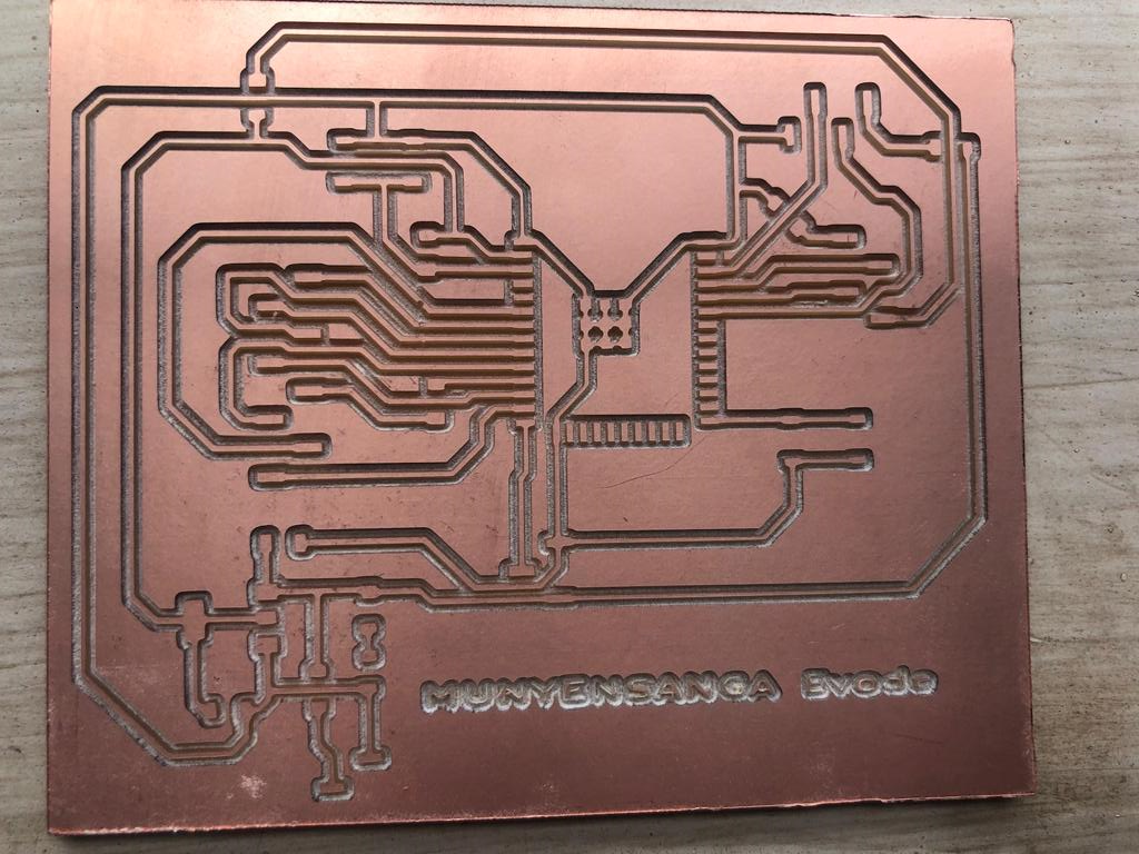
 Here is our PCB after Milling
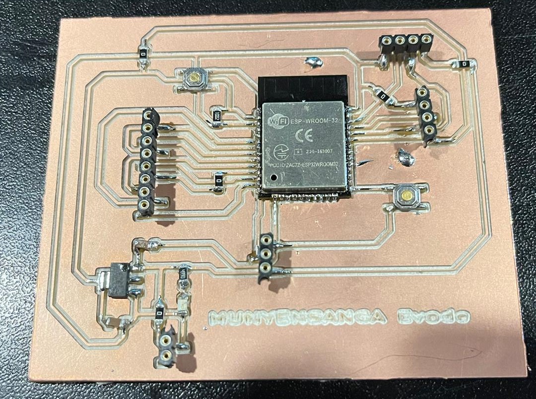
 Here is our PCB after soldering Componments
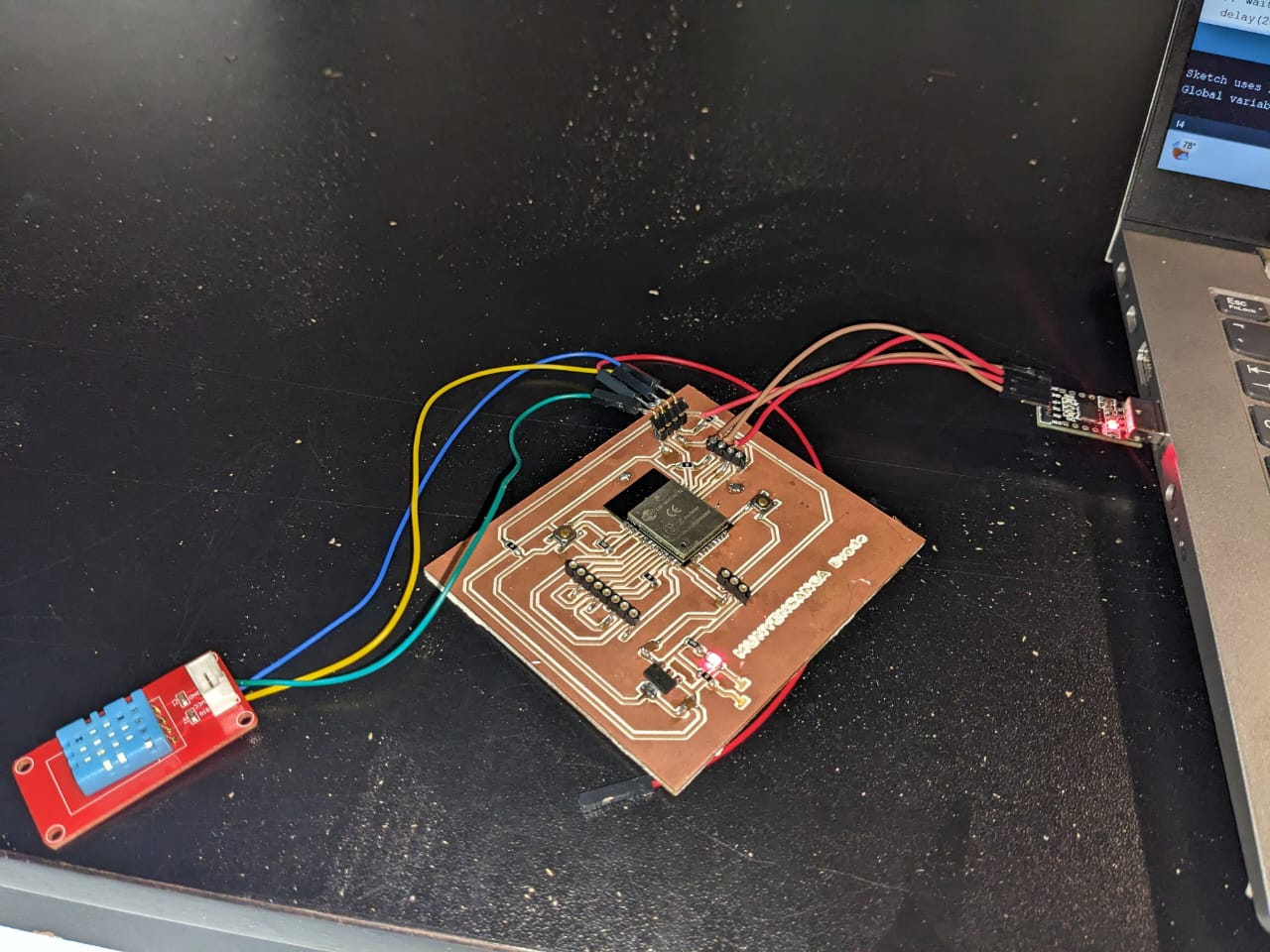
 Here we have connected our Input Sensor to the microcontroller Board
 Here are the code we run with Arduino for Input Device
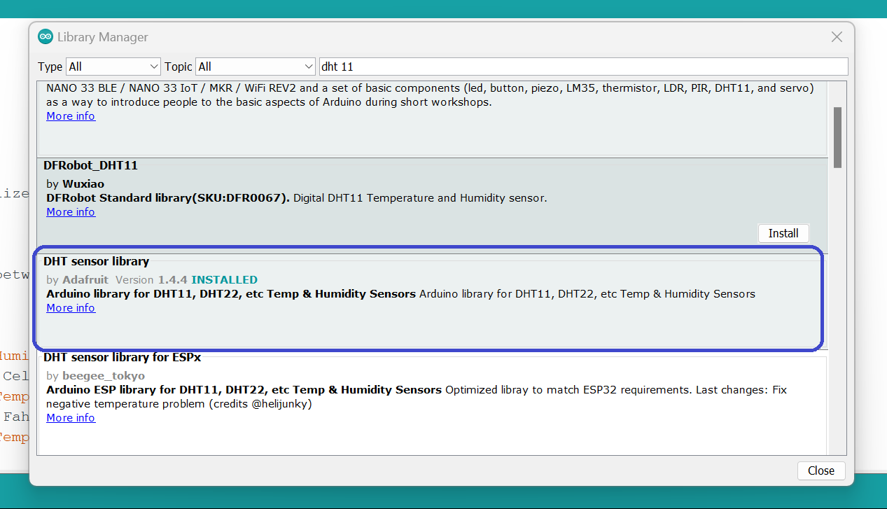
Here we Install DHT 11 Sensor libraries in Arduino for able to run our output Device
Here are the code we run with Arduino for Input Device
Here we Install DHT 11 Sensor libraries in Arduino for able to run our output Device
                            #include "DHT.h"
                            #define DHTPIN 21
                            #define DHTTYPE DHT11

                            DHT dht(DHTPIN, DHTTYPE);

                            void setup() {
                              Serial.begin(9600);
                              dht.begin(); // initialize the sensor
                            }

                            void loop() {
                              // wait a few seconds between measurements.
                              delay(2000);

                              // read humidity
                              float humi  = dht.readHumidity();
                              // read temperature as Celsius
                              float tempC = dht.readTemperature();
                              // read temperature as Fahrenheit
                              float tempF = dht.readTemperature(true);

                              // check if any reads failed
                              if (isnan(humi) || isnan(tempC) || isnan(tempF)) {
                                Serial.println("Failed to read from DHT sensor!");
                              } else {
                                Serial.print("Humidity: ");
                                Serial.print(humi);
                                Serial.print("%");

                                Serial.print("  |  ");

                                Serial.print("Temperature: ");
                                Serial.print(tempC);
                                Serial.print("°C ~ ");
                                Serial.print(tempF);
                                Serial.println("°F");
                              }
                            }
.png)
.png) For found my final results of input device watch the following Video
For found my final results of input device watch the following Video
If you want to learn about my code, kindly click here