Week 6: Electronics Design
Electronics Design
Assignment activities:
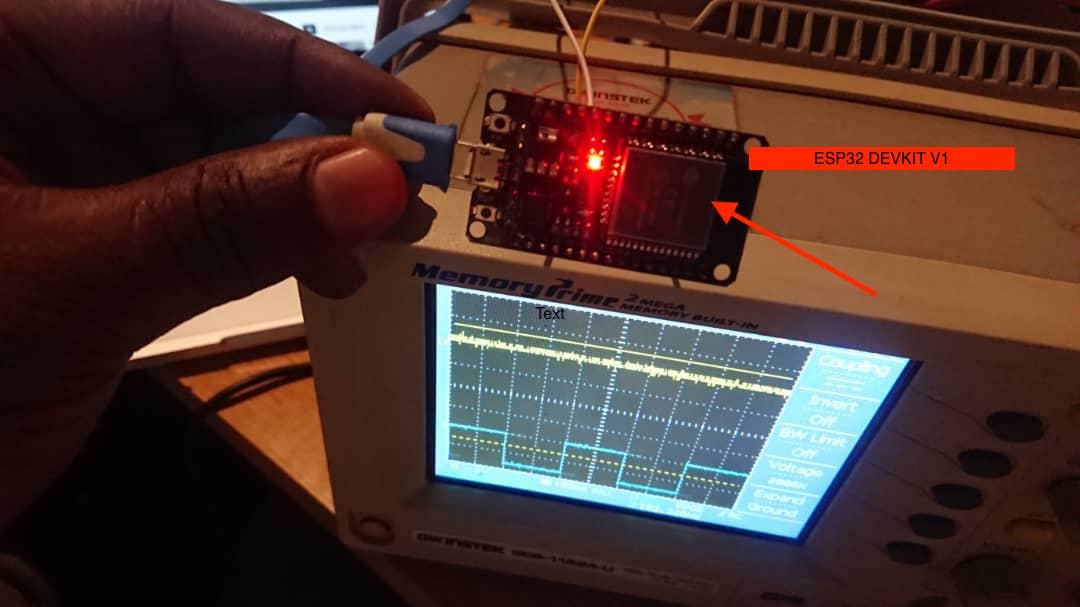
Group assignment:Use the test equipment in your lab to observe the operation of a microcontroller circuit board
I.Group Assignment:
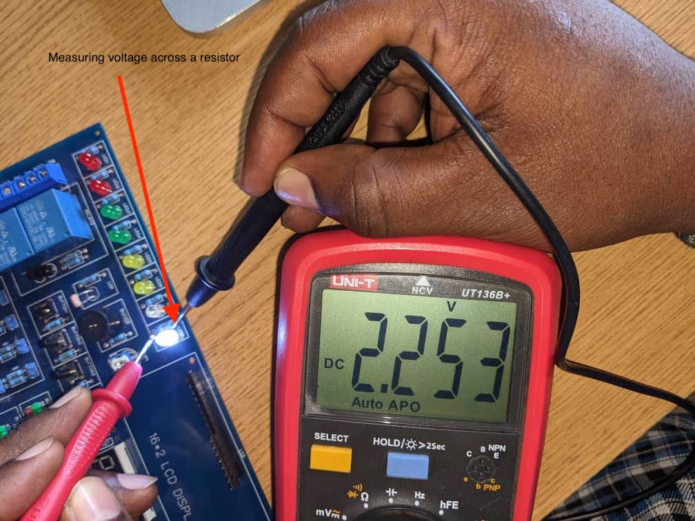
If you want to explore the group Assignment Click Here Lab Test Equipments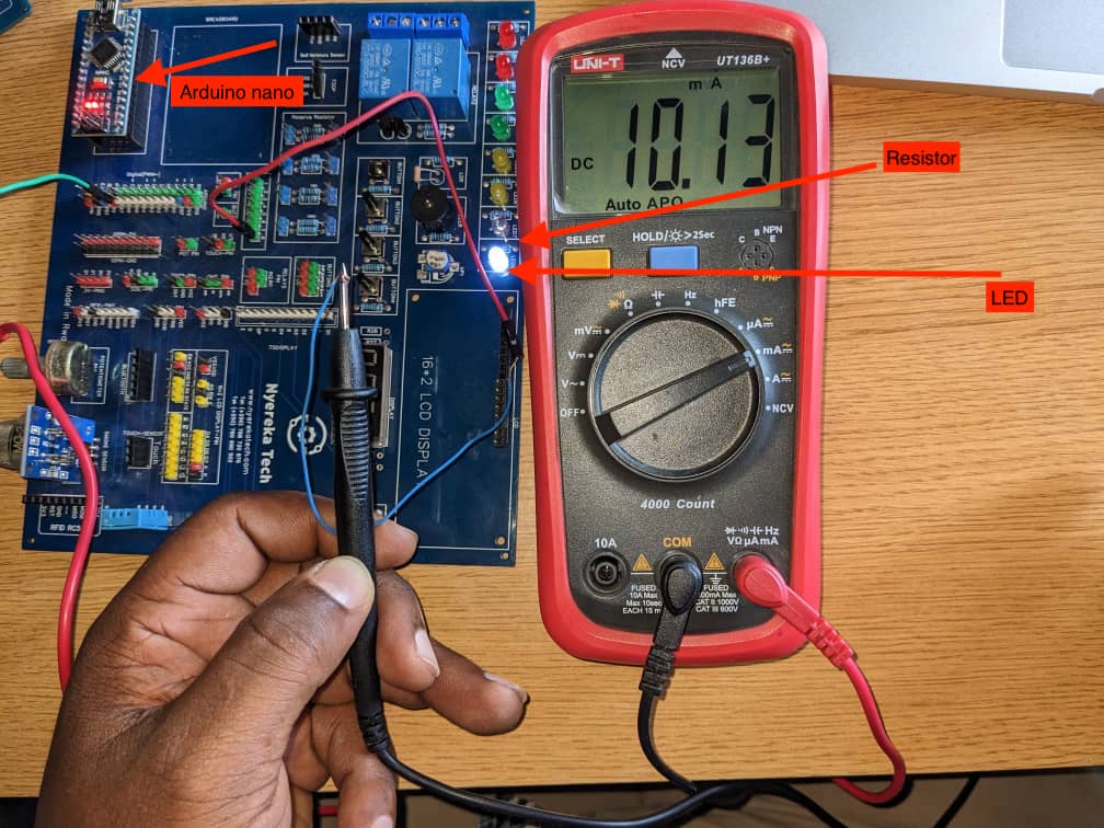 b. Measuring voltage with Multimeter
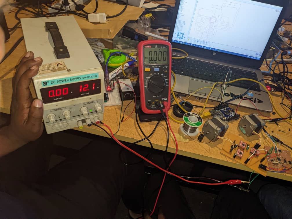
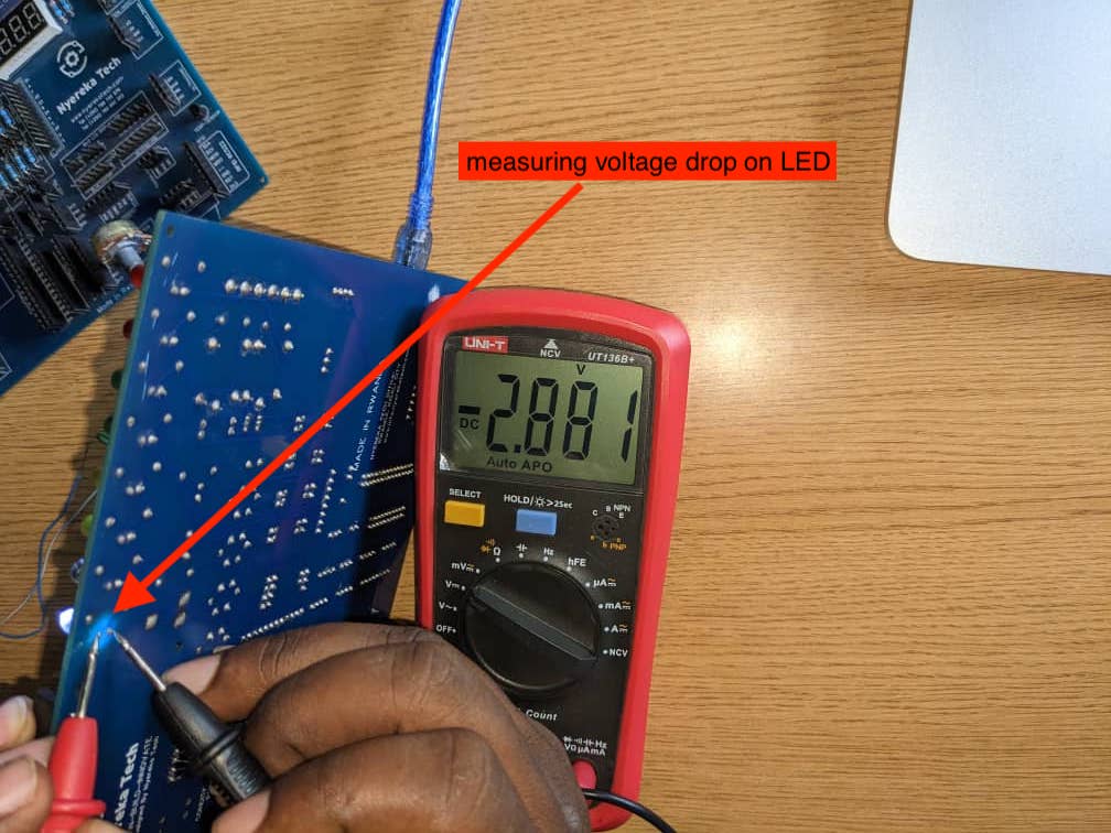
 c. Measuring Voltage droped on Led
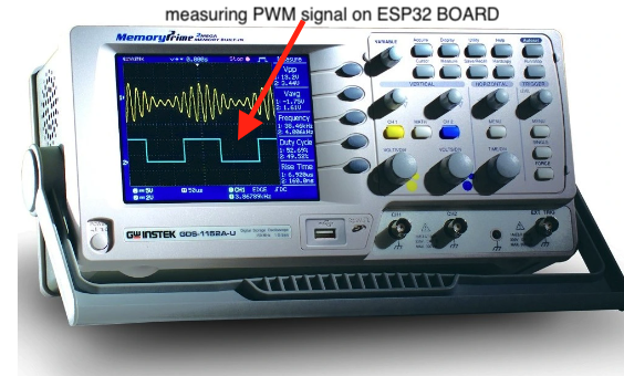
 And also we used Oscilloscopes which have a display screen that shows the waveform of the signal being measured. The horizontal axis represents time, while the vertical axis represents voltage.
 A DC power supply is an electronic device that converts an AC (alternating current) voltage from the wall outlet into a stable DC (direct current)
II.Individual assignment:
design a development board to interact and communicate with an embedded microcontroller
What is Electronics Design?
Electronics design is the process of creating circuit boards and electronic systems using various hardware and software tools. This process involves designing and testing circuits, selecting appropriate components, and creating schematics and layouts that can be used for manufacturing.
In this Assinment we used Kcard Software
Kicad is an open-source software suite used for electronic design automation (EDA) that facilitates the creation of schematic diagrams and printed circuit board (PCB) layouts. It is widely used in the electronics industry and by hobbyists to create complex electronic systems. Kicad is a cross-platform software, which means it can be used on different operating systems like Windows, Linux, and Mac. It has a user-friendly interface that enables users to easily navigate and use its different tools and features. For more about Kcard and if you want to download Kcard click here In this Assinment we learnt about PCBPCB stands for Printed Circuit Board, which is a fundamental component in electronic design. A PCB is a flat board made of insulating material (typically fiberglass or plastic) with conductive tracks etched onto its surface. The tracks are used to connect different components of an electronic circuit together. The process of creating a PCB involves several steps. First, a schematic diagram of the circuit is created using EDA software like Kicad. This schematic is then used to create a physical layout of the PCB using specialized software. The layout includes the placement of components, routing of tracks, and the positioning of mounting holes. For more about PCB click here
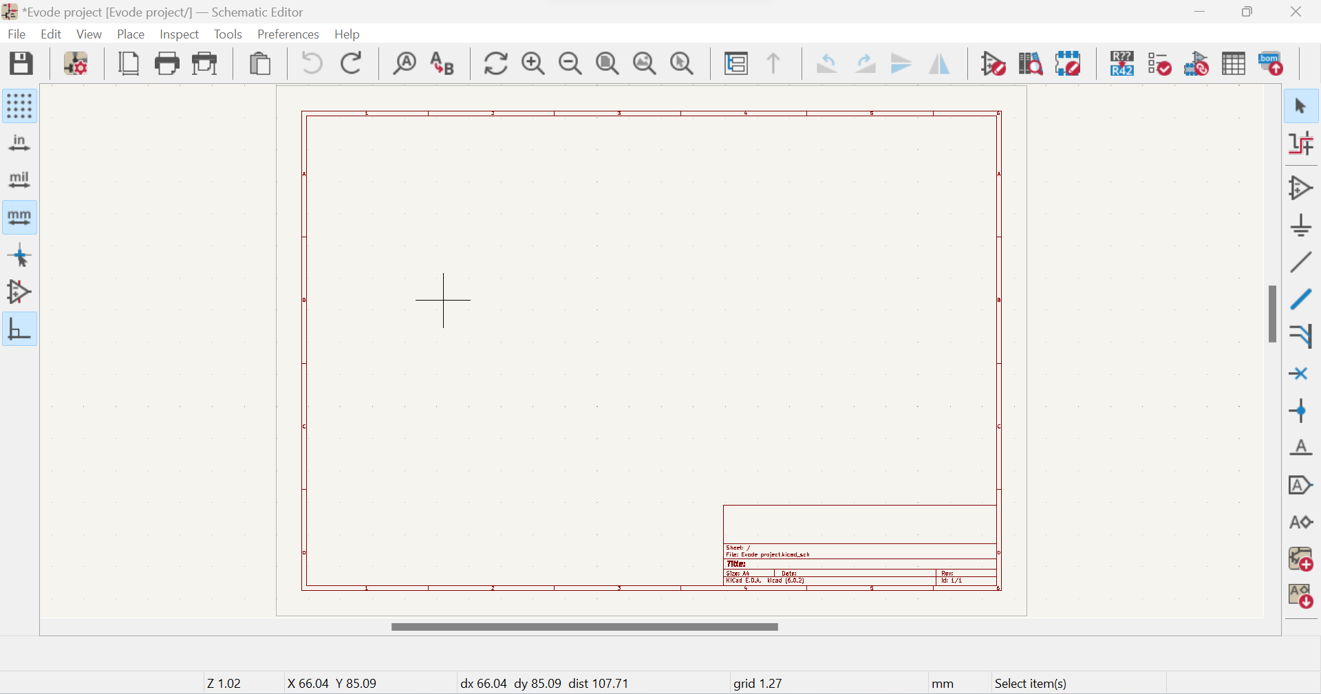
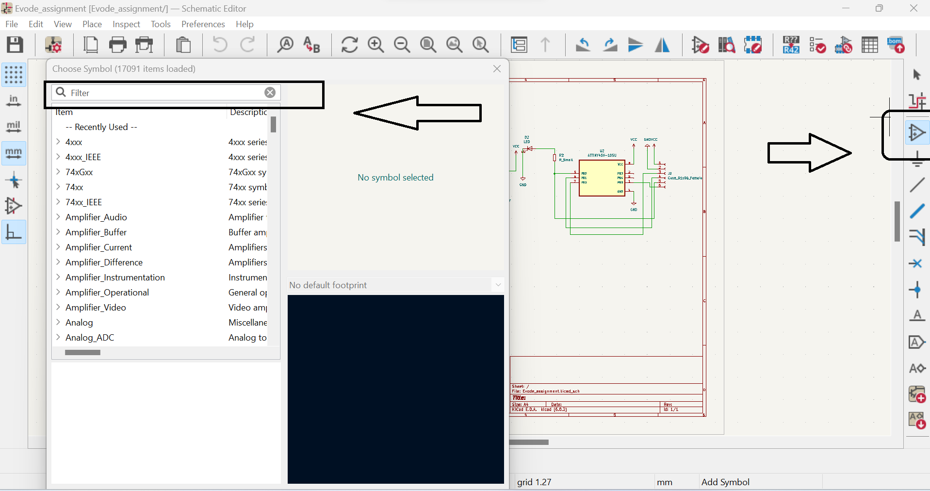
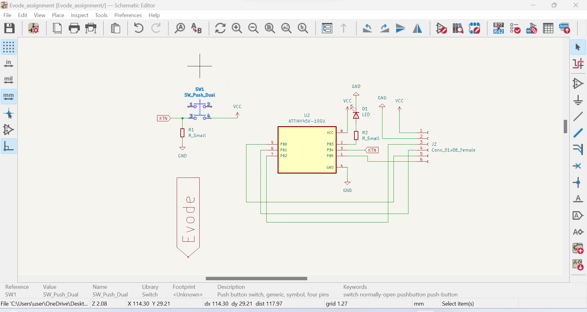
Here are the steps to design a PCB using Kcard:1.Create a new PCB project: Open Kcard and create a new PCB project. Set the board size and other properties such as the number of layers, board thickness, and trace width:
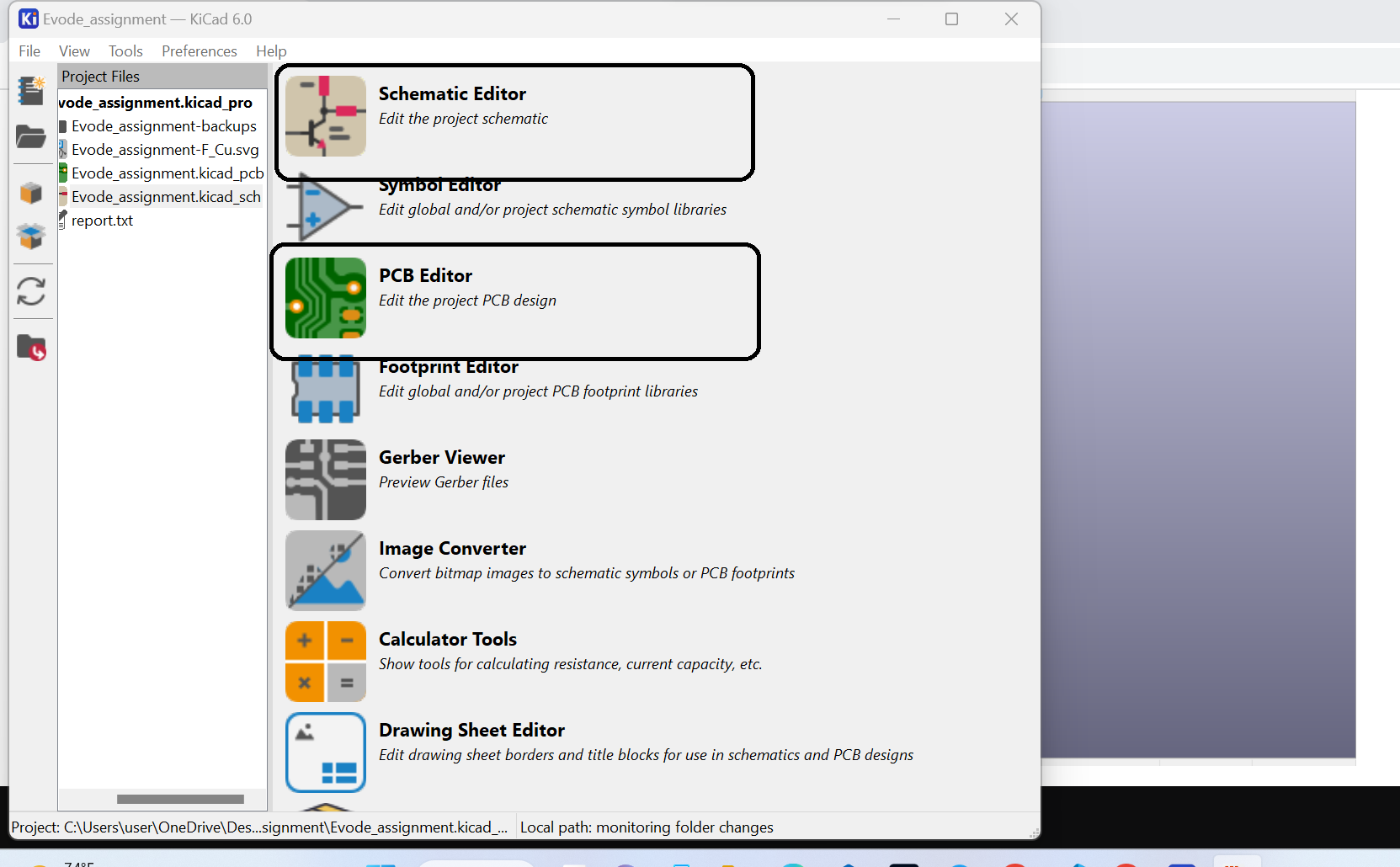 a. Open Kcard and create a new PCB project
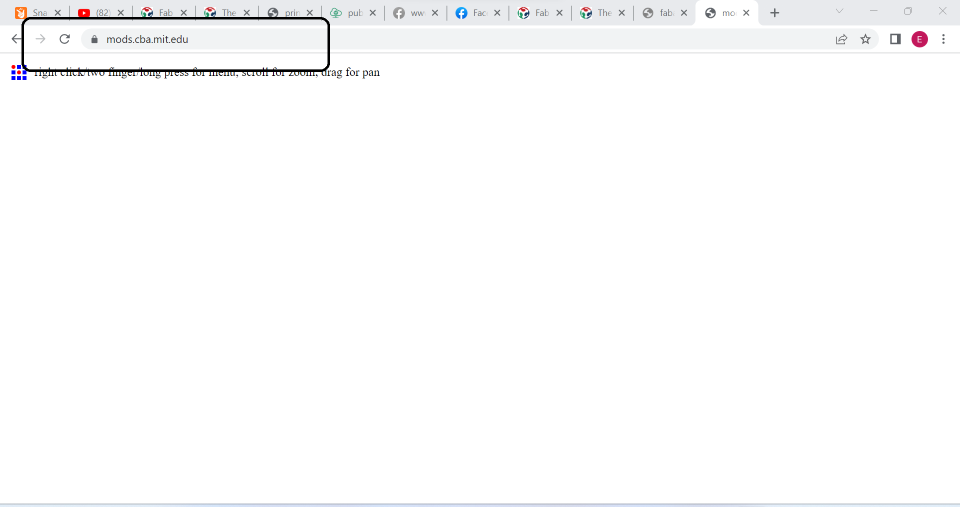
a. Open mods.cba.mit.edu: Once your design file is ready, go to mods.cba.mit.edu in your web browser.
b.Select "Mill" mode: Click the "Mill" button in the top left corner of the mods.cba.mit.edu interface to switch to mill mode.
b.1 Selcet program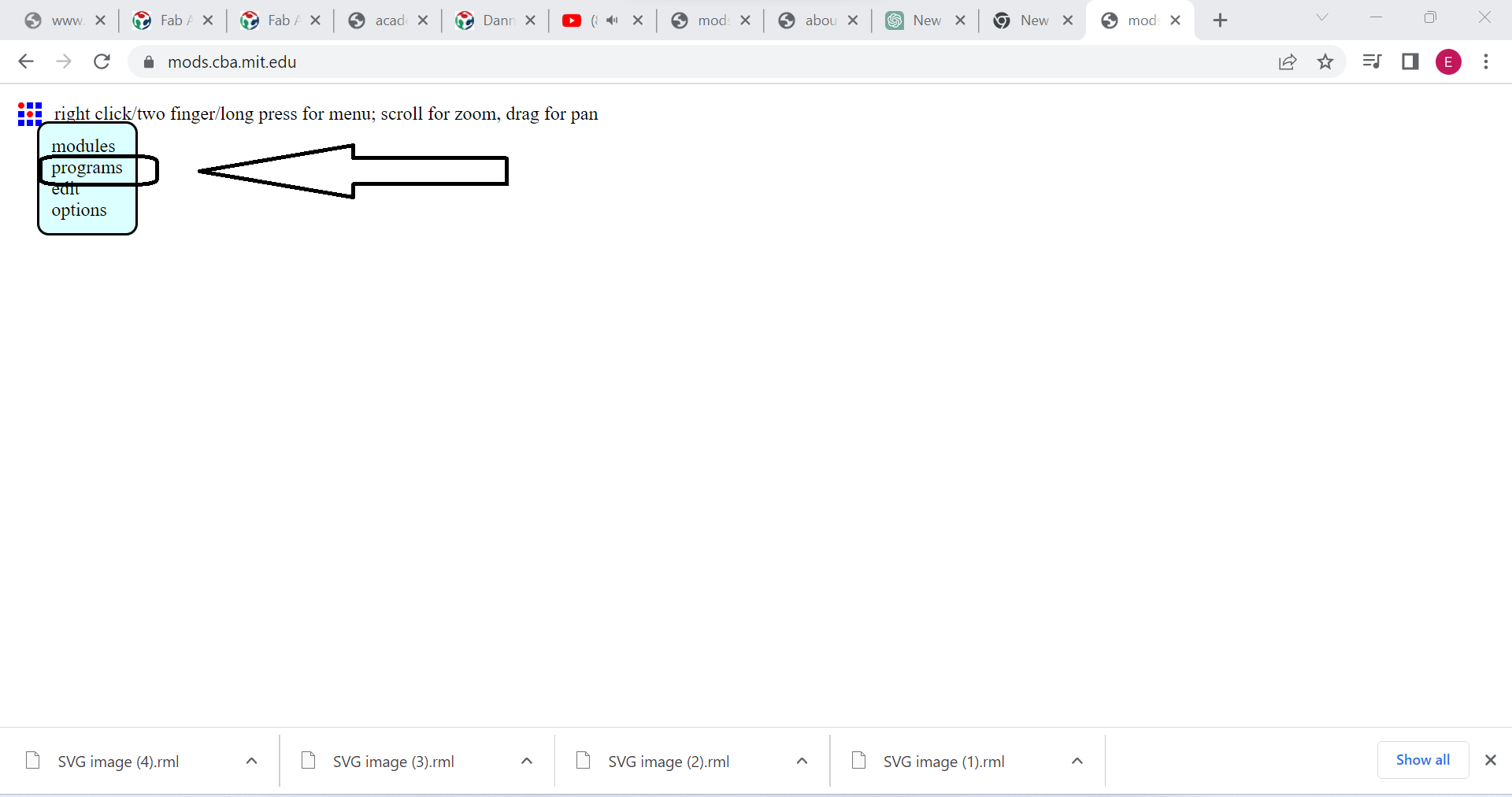
b.2 Selcet program server
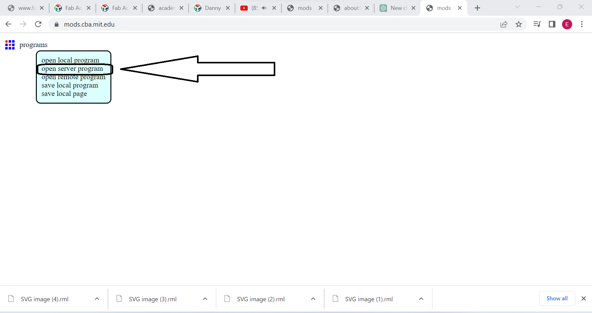
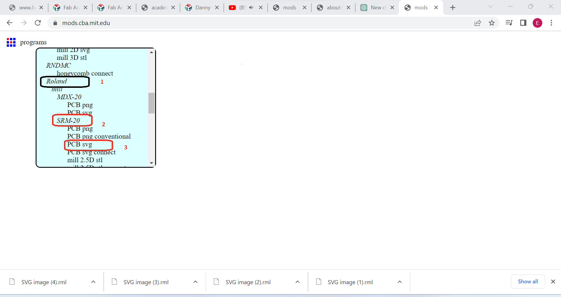
b.3 Selcet Roland,srm,and format svg
4.Import your design file: Click on the "Import" button in the top left corner of the interface and select the design file that you prepared earlier. The design will then be displayed in the mods.cba.mit.edu interface.
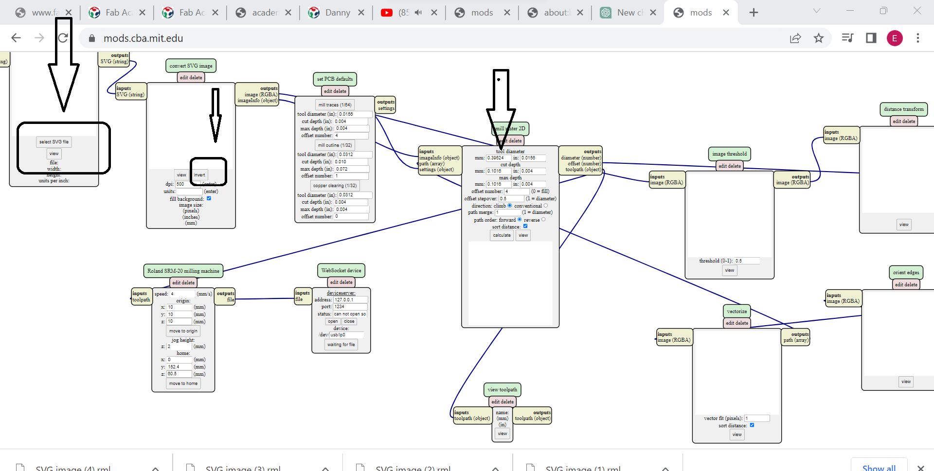
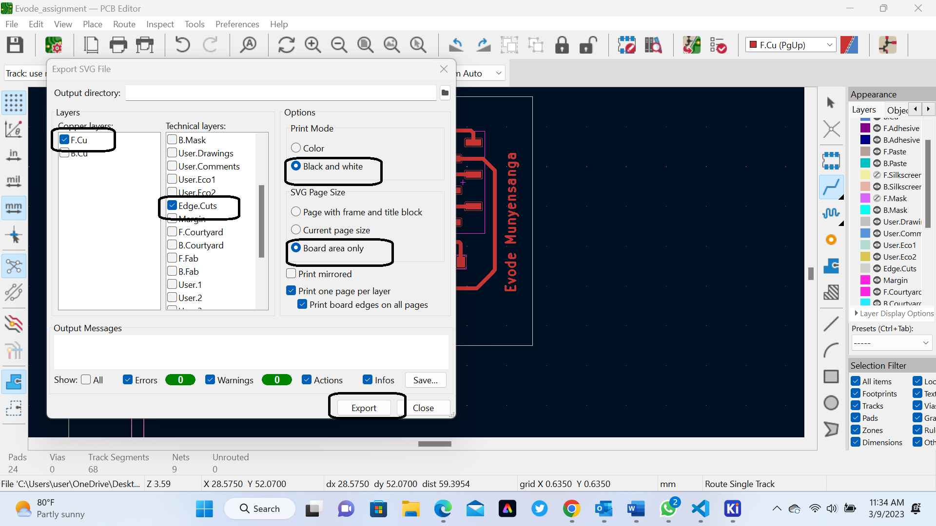
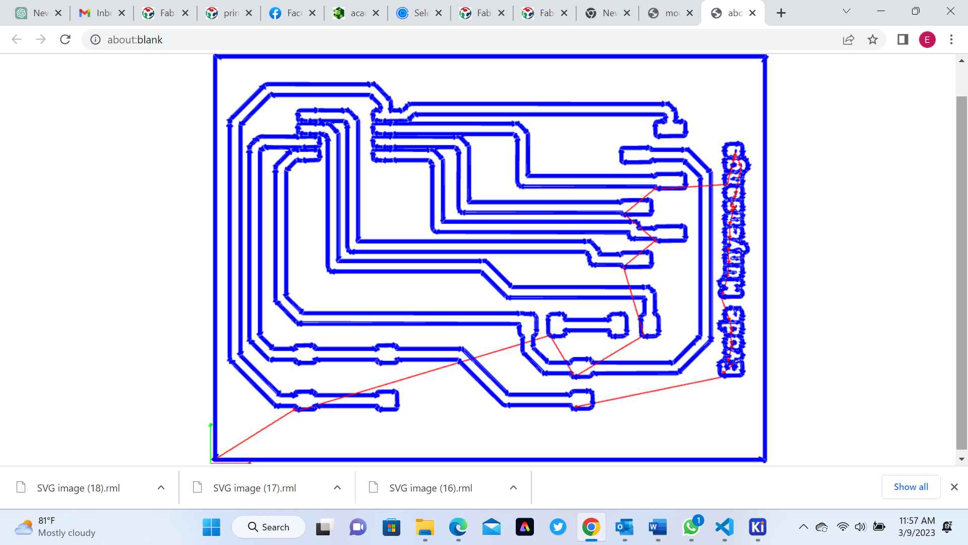
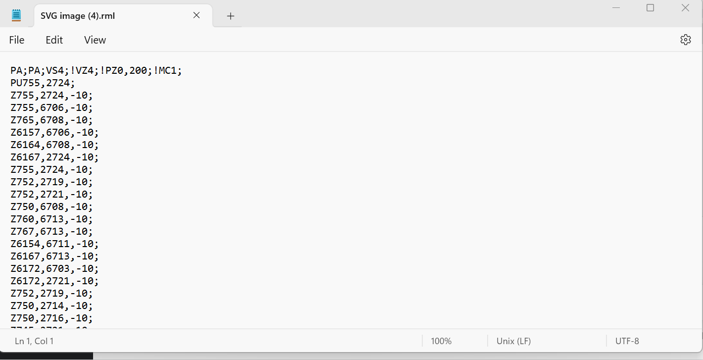
5. Generate G-code: Once your milling parameters are set up, click the Calculate button in the bottom right corner of the interface. The mods.cba.mit.edu software will then generate G-code instructions that can be used to control your milling machine. The following image are the output downloaded file
6.Save the G-code file: Save the G-code file to your computer by clicking the "Download" button in the bottom right corner of the interface.
7. Load the G-code file onto your milling machine: Finally, load the G-code file onto your milling machine using the instructions provided by the manufacturer. Your machine should then be ready to mill your design
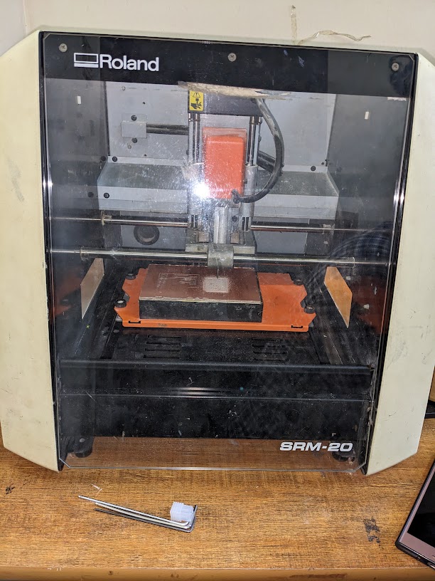
In our Assignment we use The Roland SRM-20
The Roland SRM-20 is a 3-axis desktop milling machine designed for rapid prototyping and production of small parts, including PCBs (Printed Circuit Boards). It is widely used in industries such as engineering, manufacturing, product design, and education.Here are some of the key features and specifications of the Roland SRM-20 milling machine:
- 1. Workspace: The milling machine has a 203 mm x 154 mm x 60 mm (X, Y, Z) workspace, which is sufficient for milling small parts.
- 2. Resolution: The SRM-20 has a resolution of 0.01 mm, which allows for precise milling of small details.
- 3. Spindle: The machine comes with a high-precision spindle capable of speeds up to 15,000 RPM.
- 4. Software: The SRM-20 comes with VPanel software, which allows for easy setup and operation of the machine. The software also includes features for toolpath generation, cutting simulation, and more.
- 5. Materials: The machine can mill a wide range of materials, including plastics, woods, metals, and PCBs.
- 7. Connectivity: The SRM-20 can be connected to a computer using a USB cable, making it easy to transfer files and control the machine.
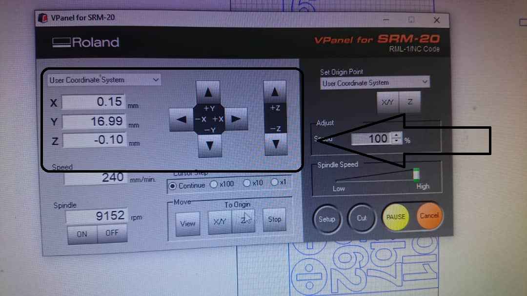
- 1. Open the Roland SRM-20 software, VPanel.
- 2. Load the Gerber files into VPanel by selecting "File" "Import" and selecting the relevant files.
- 3. Once the files are loaded, select "Layout" in the "Model" section of VPanel.
- 4. Place the end mill (milling bit) at the starting point for milling on the PCB.
- 5. Use the X, Y, and Z axes in VPanel to move the end mill to the exact position that you want to set as the origin point for milling.
- 7. The origin point is now set, and you can begin milling your PCB.
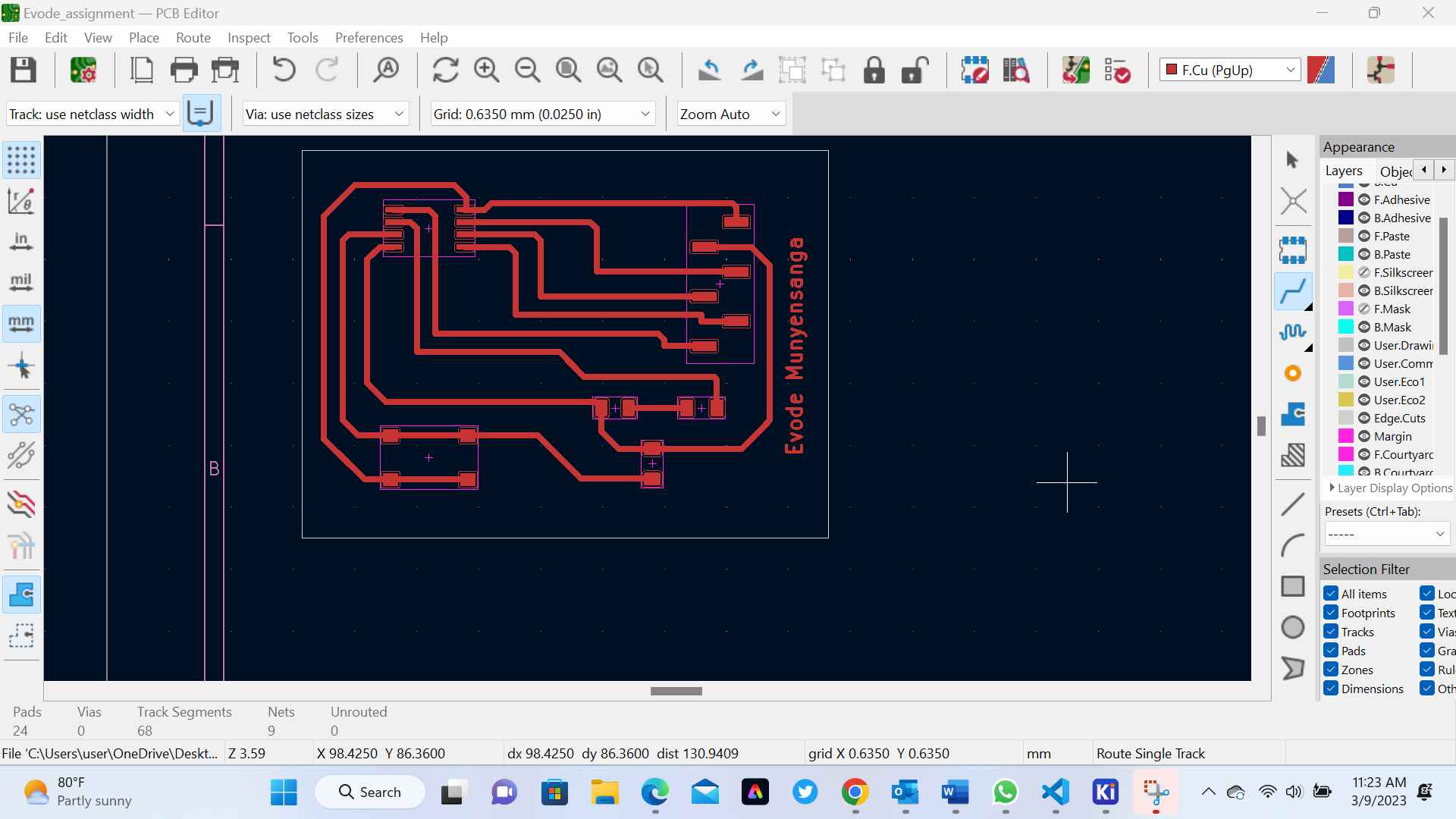
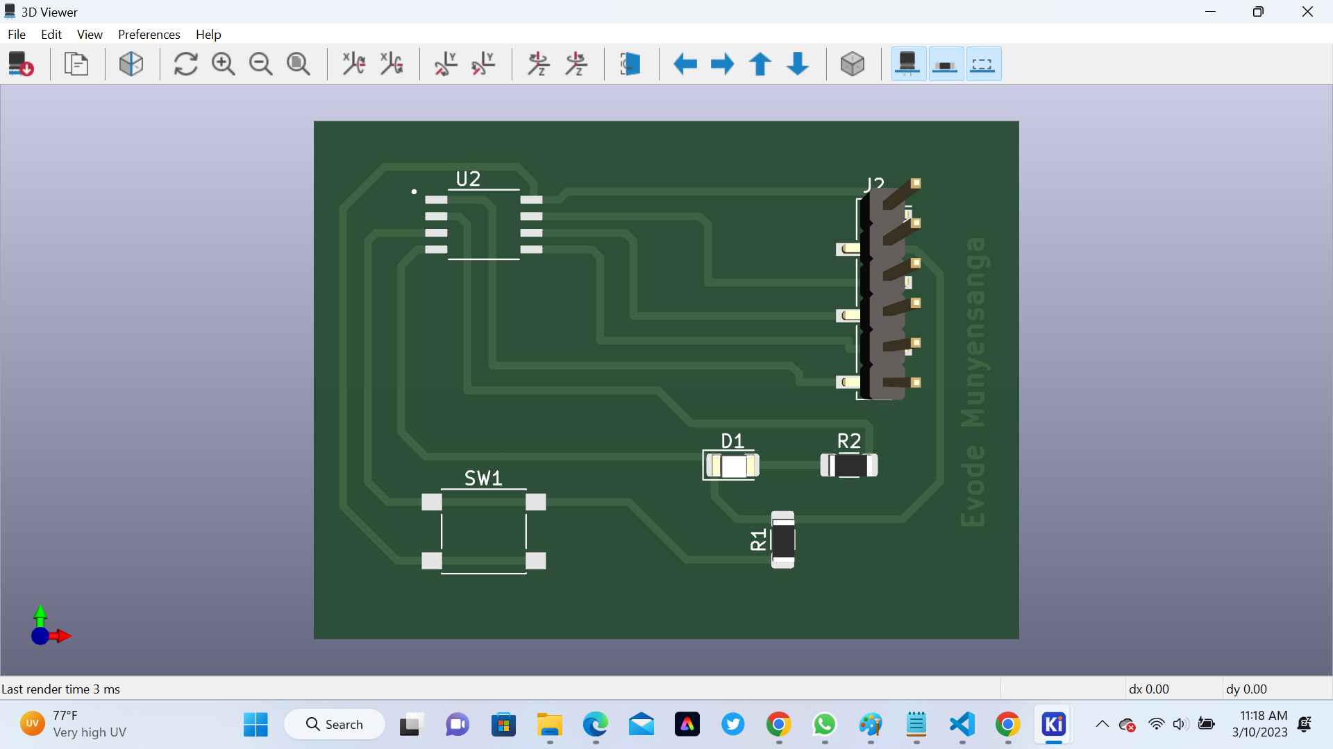
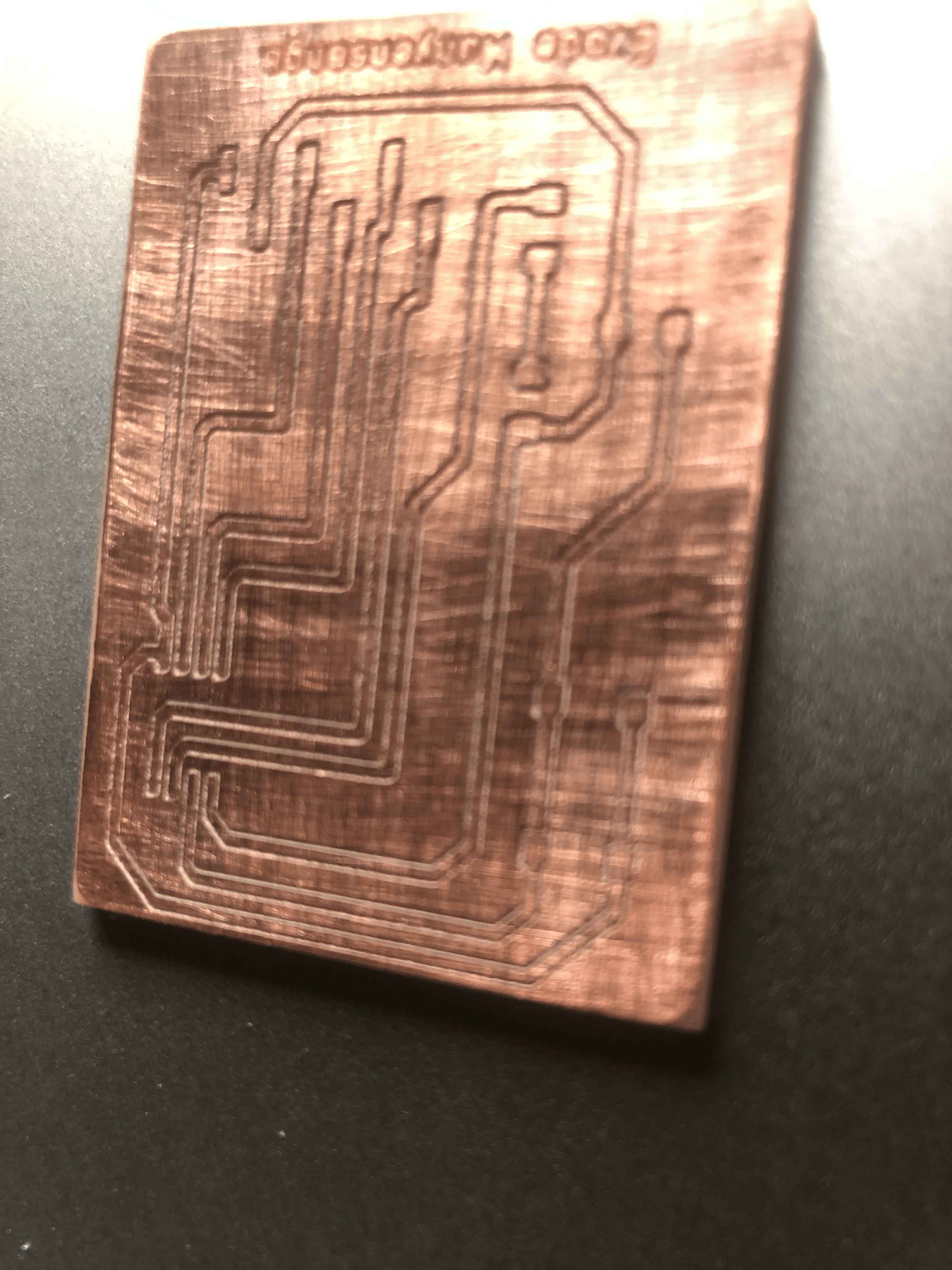
After Printing my PCB, the below immage is my output
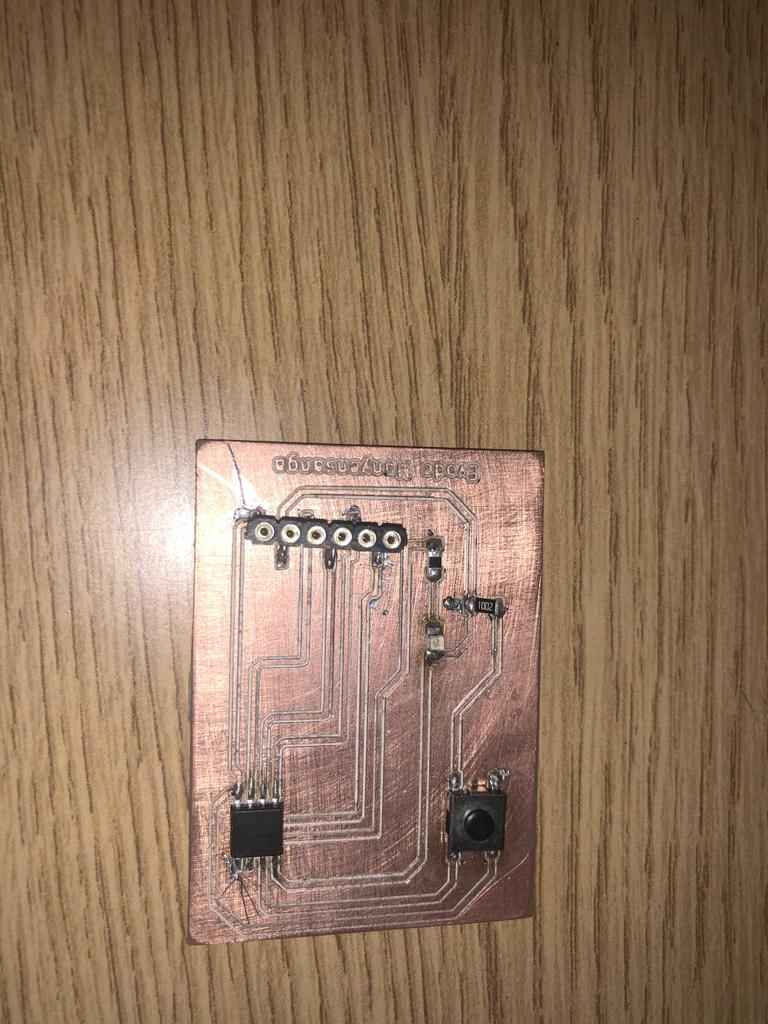
After I tried Soldering components on pcb

Final PCP Soldered
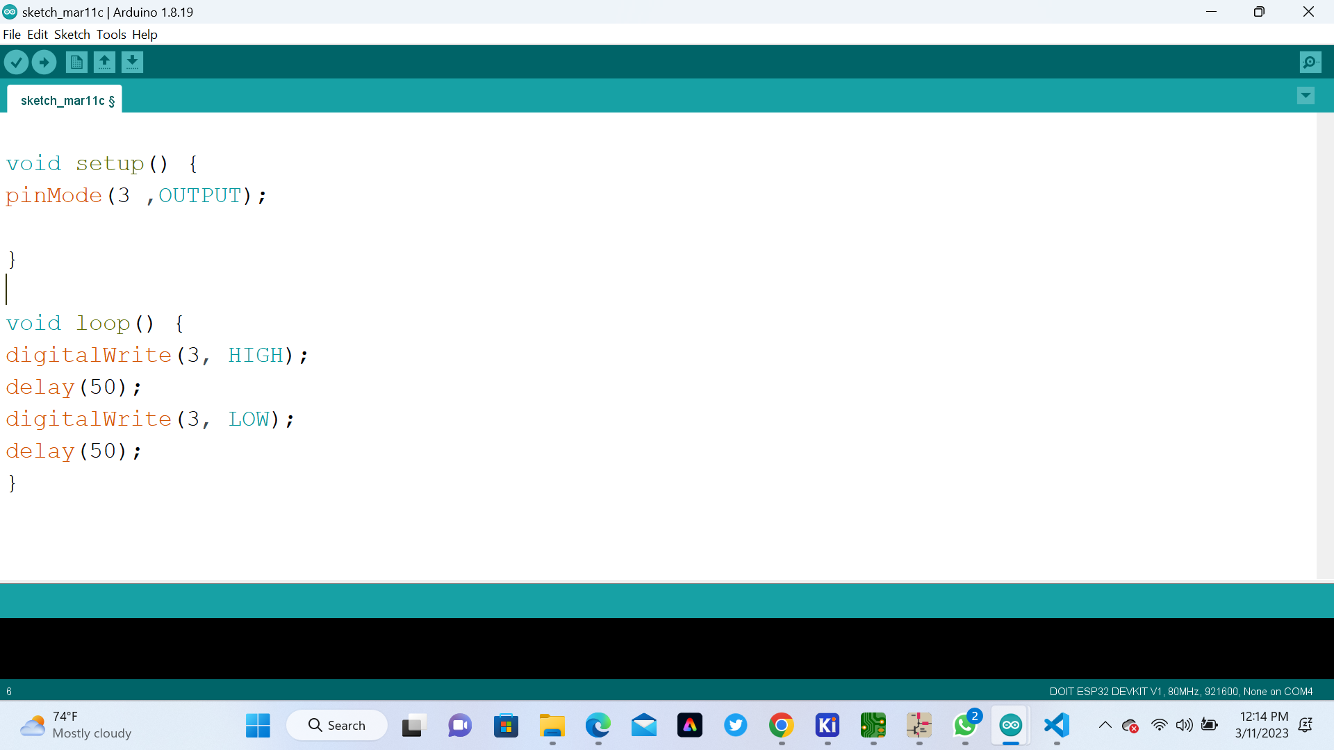
Here are the code we used to program our microcontroller in order to control how to blink LED
                                                void setup() {
                                                    pinMode(3 ,OUTPUT);

                                                    }

                                                    void loop() {
                                                    digitalWrite(3, HIGH);
                                                    delay(50);
                                                    digitalWrite(3, LOW);
                                                    delay(50);
                                                    }
This is the program I wrote.
To show if the Microcontroller ATtiny45 successful to blink the Led watch the below Video
If you want to learn about my designers, kindly click here for downloading my files