Week 11: Input Devices
Group assignment
-
* Probe an input device(s)'s analog and digital signals
-
* Document your work on the group work page and reflect on your individual page what you learned
The group assignment page is here on FabLab Rwanda web page
.Individual assignment
What exactly are input devices?
In an electronic circuit, an input device (sensor) reacts to changes in the environment by producing an electrical signal. There are many different ways to measure inputs using sensors, which also detect other types of energy that are later converted into electrical energy.-
Below here, I am going to add a motion sensor to a microcontroller board that I have designed and read it.
-
Therefore, I am going to use the same board I used in Week9 of Output Devices
This week, I chose to use A passive infrared sensor (PIR sensor) as the input device.
PIR sensors allow us to sense motion. They are used to detect whether a human has moved in or out of the sensor's range. They are commonly found in appliances and gadgets used at home or for businesses. They are often referred to as PIR, "Passive Infrared", "Pyroelectric", or "IR motion" sensors.
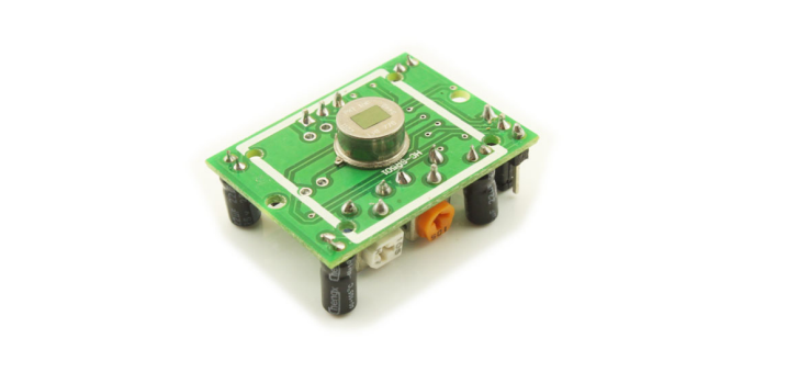
PIRs are basically made of a pyroelectric sensor (which you can see above as the round metal can with a rectangular crystal in the center), which can detect levels of infrared radiation. Everything emits some low level radiation, and the hotter something is, the more radiation is emitted. The sensor in a motion detector is actually split in two halves. The reason for that is that we are looking to detect motion (change) not average IR levels. The two halves are wired up so that they cancel each other out. If one half sees more or less IR radiation than the other, the output will swing high or low.
DYP-ME003 PIR Sensor Module
This module is based on BISS0001 PIR motion detector IC, which processes the output of the analog sensor and transforms it in a digital signal. This modules allows you to detect motion, and it's most frequent use is to determine when a human has moved into the sensing range. The PIR sensor is covered by Fresnel Lens, which increase the range and define the sensing pattern of the module.| DYP-ME003 PIR Sensor Module | |
|---|---|
|
|
-
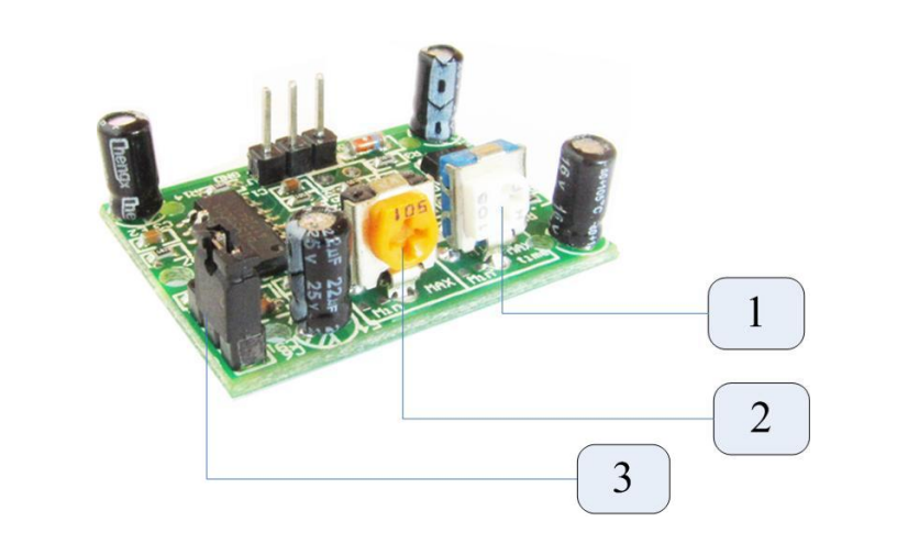
(1) Delay Time Potentiometer:
The delay time represents the duration of the output high signal. The minimum delay time is 5 s and the maximum delay time is 300 s. This parameter can be adjusted using potentiometer (1) -
(2) Distance Potentiometer:
The maximum detection range of this module is adjustable between 3 m and 7 m. It can be adjusted using potentiometer (2). -
(3) Trigger Mode Jumper:
This module also features a two trigger modes: single trigger and repeatable trigger. The trigger mode can be configured using jumper (3)
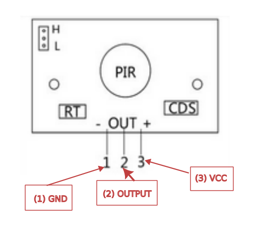
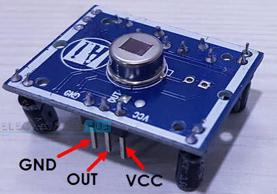
The Pinout
|
|
- When the trigger mode jumper is connected to “L”, the module is configured to use a single trigger. Setting the jumper in the “H” position configures the module to use a repeatable trigger. The default trigger is the repeatable one.
Below here are used code to run the above connected PIR Motion Sensor
         int motionPin = 3;
         int ledPin = 4;

         void setup(){
              pinMode(motionPin, INPUT);
              pinMode(ledPin, OUTPUT);

         }

         void loop(){
              if (motionPin == HIGH){
                   digitalWrite(ledPin, HIGH);
              }
              else {
                   digitalWrite(ledPin, LOW);
              }
              delay(100);
         }
Below here is the taken 'hero shot'
- Used file can be found here
© 2023 | Eric NDAYISHIMIYE | All Rights Reserved