- microcontroller
- power supply
- stepper motors
- stepper motor driver
- wires and connectors
- cnc shield
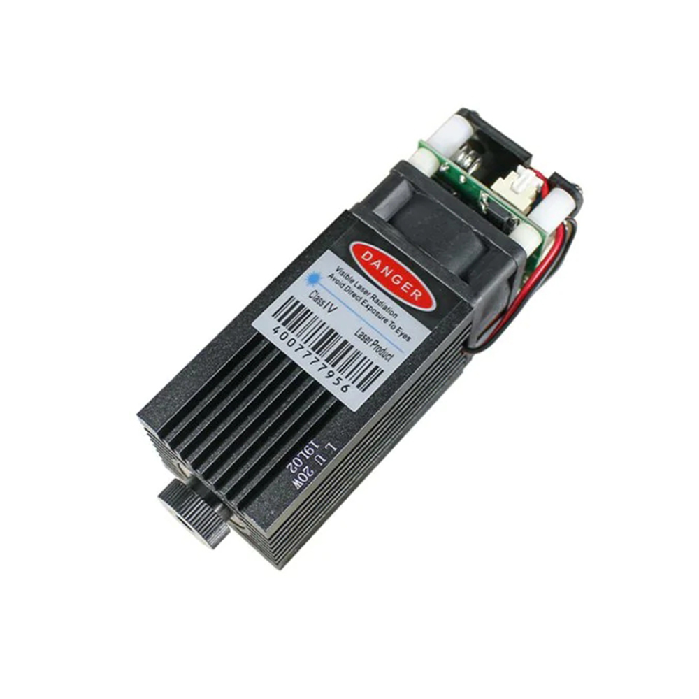
- laser head
machine design
this week focuses on machine design
we have made the machine in a group where we made a laser machine all work done can be found through this link LINK HERE Group_Assignmenteveryone in a group has done an individual work participation to be done so my work was all about electronics introduced on the machine
there's a requirements needed for the machine to works here's the list below of all used components and devices
microcontroller
microcontroller is is a small and low-cost microcomputer, which is designed to perform the specific tasks of embedded systems like displaying microwave’s information,receiving remote signals. this LINK HERE expalins deeply about microcontroller
for the machine to operate i we have decided to use ATMEGA328p which is commonly used microcontroller so used in arduino uno and nano
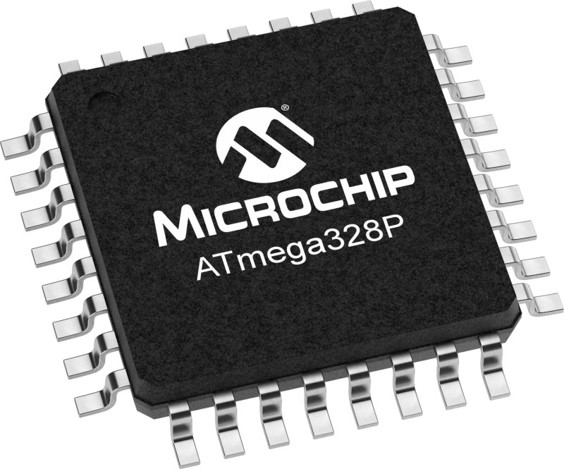

more about microcontroller download here datasheet
power supply
the second device or element i have used is power supply, is an electrical device that supplies electric power to an electrical load.for our project composed with more devices they all need to be powered, power supply mostly has different power output that is provided
it can be aither fixed power Power_supply or variable power output depending on power load read about power supply here download datasheet here
stepper motors
as we have made a laser cutter machine, so the movement of the axis is supported by stepper motorsso we have used 2 neema 23 motors and 1 neema 17 stepper motor for different axis
neema 17
we have used neema 17 to drive Y-axis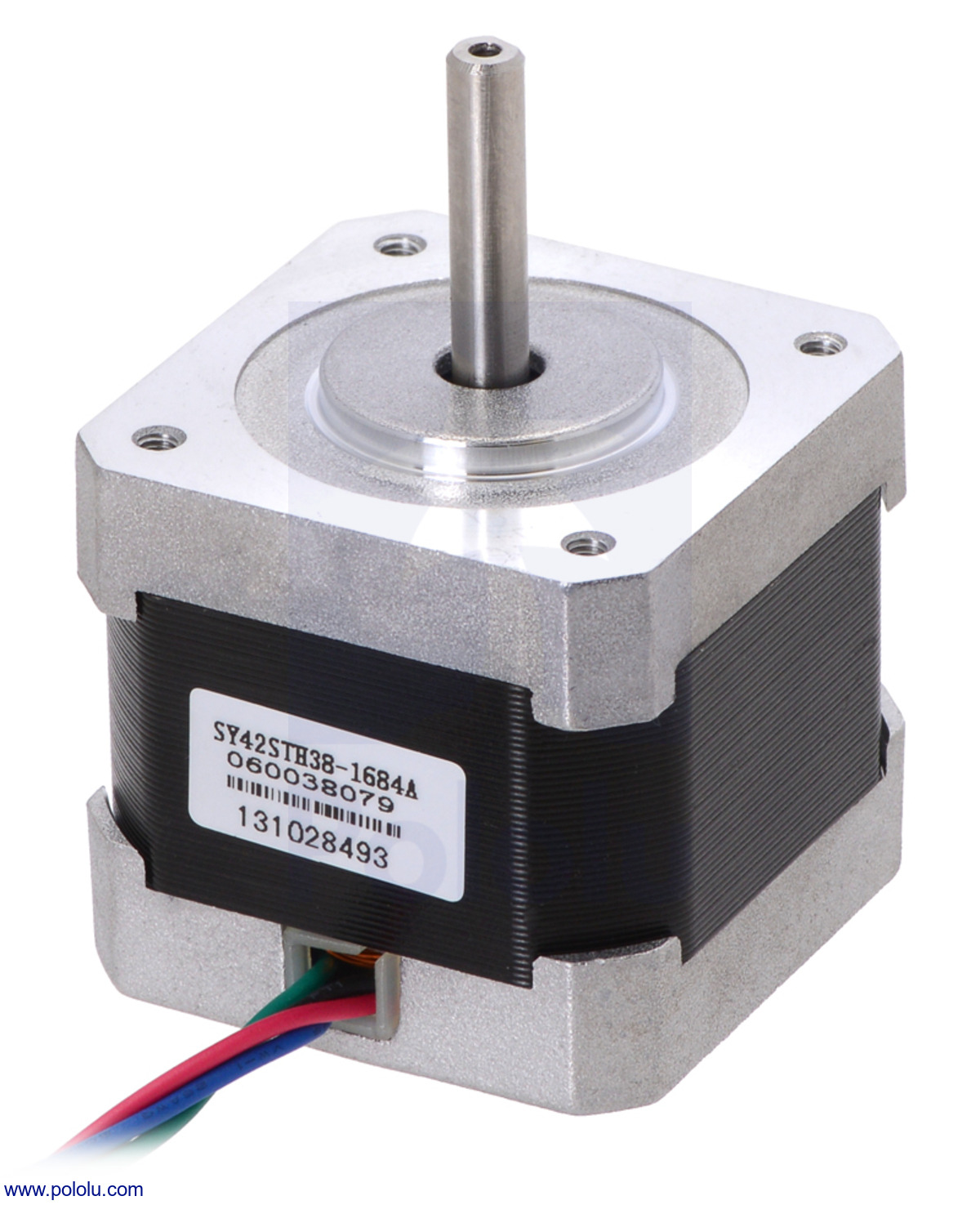
https://reprap.org/wiki/NEMA_17_Stepper_motor
neema 23
we have used neema 23 to drive x-axis
https://reprap.org/wiki/NEMA_23_Stepper_motor
stepper motor driver
Stepper motor drivers are specifically designed to drive stepper motors, which are capable of continuous rotationwith precise position control, even without a feedback system.
TB6600
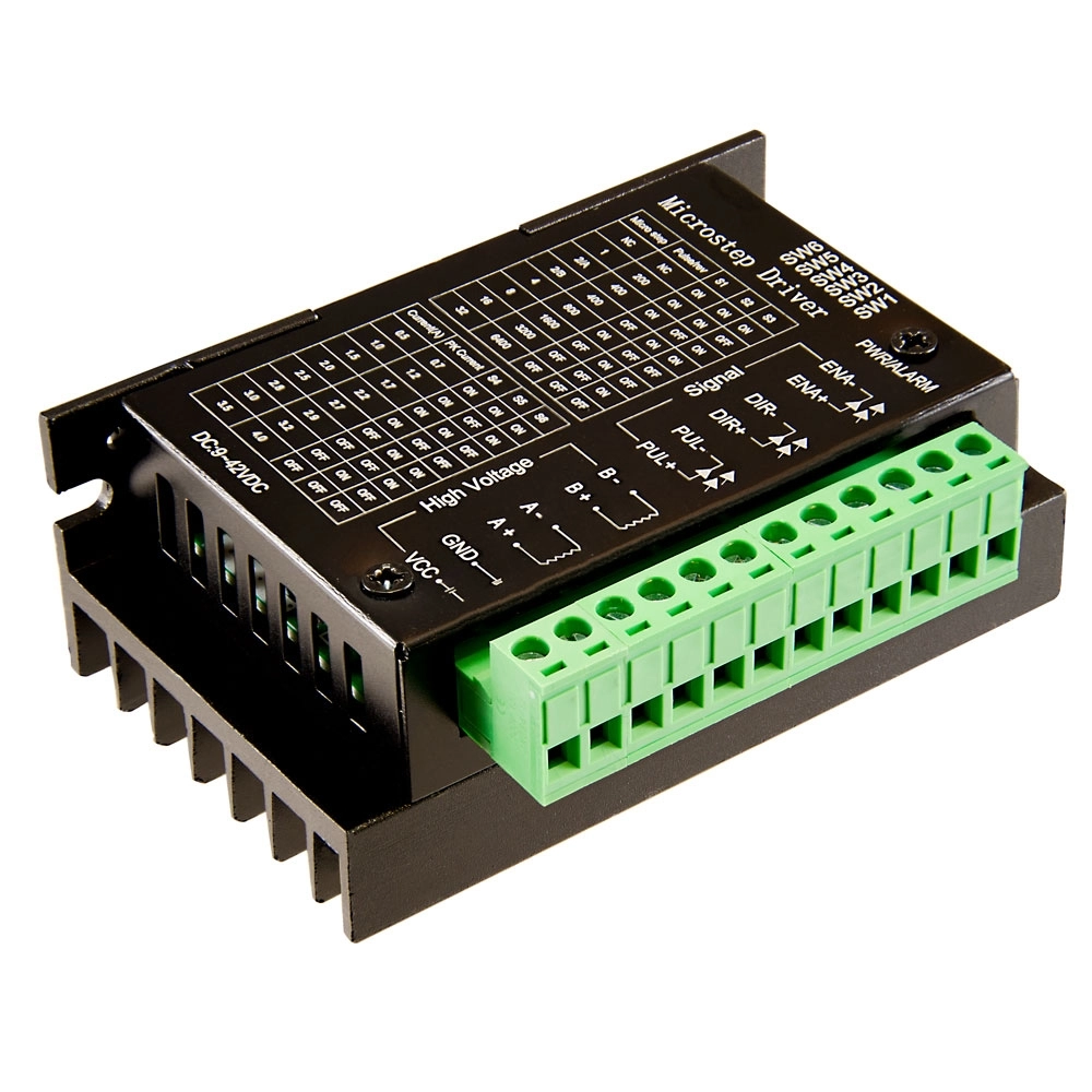
https://www.watelectronics.com/tb6600-stepper-motor-driver-module/
A4988
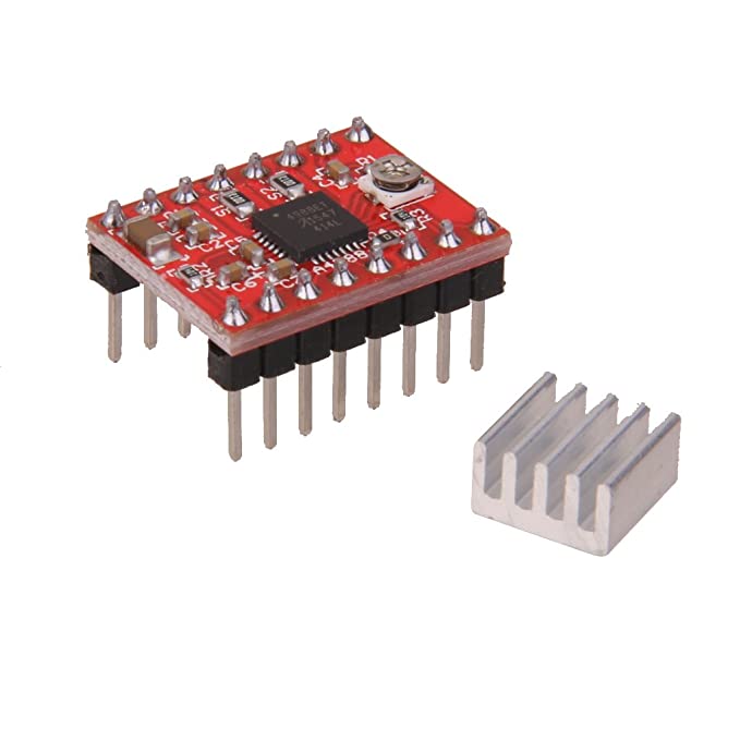
https://www.alldatasheet.com/view.jsp?Searchword=A4988&gclid=Cj0KCQjw3a2iBhCFARIsAD4jQB1l-mRHh2WlIHkcXCu6h99Y0aMXige4ydNAnp6D77Q1qFoXACkuDCUaAtDmEALw_wcB
cnc shield
is an open source hardware used to control stepper motors. Allows you to control 4 motors simultaneously. It uses removable A4988 stepper controls.Stepper motors are connected via 4-pin connectors. Its supply voltage is 12-36 V. The stepper motor is ideal for projects requiring controlled rotation. learn cnc shield
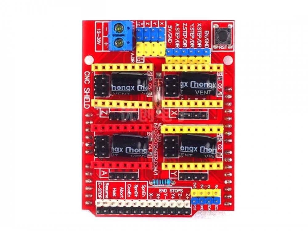
download datasheet here
connecting wires
when connecting wires it necessary to use them becouse they help to connect from one sine to another side of components and devices and make connections between them
https://learn.adafruit.com/wires-and-connections?view=all
laser head
A laser cutting head is a module of a laser cutting machine that focuses the laser beam onto the material being cut.It is typically made up of a nozzle and lens assembly that is mounted on a moving arm or gantry, which directs the laser
beam to the exact location where the cut is to be made
my cotribution to the group assignment
so my contribution to my group assignment is all about electronics softwarei started making whole machine block diagram design as a plan for the project how they will be

the LaserGRBL software will generate gcode to the laser machine with the help of the GRBL firmware and the output is laser machine
for the software to be used are
for the firnmware of the project i have used GRBL firmware it is a premade firmware that is made for controlling
machine axis control.
from this link HERE there's more about this firmware and how to use it
direct link to download the firmware from their github is https://github.com/grbl/grbl
so in my group i was assigned to install the controller firmware that is able to control the laser machine
from the above firmware i have directly downloaded it from there
.png)
then i have downloaded the file the following steps shows how to install and flash it in microcontroller
i opened arduino ide then fro tabs i clicked on sketch>> include library>> add .zip library
.png)
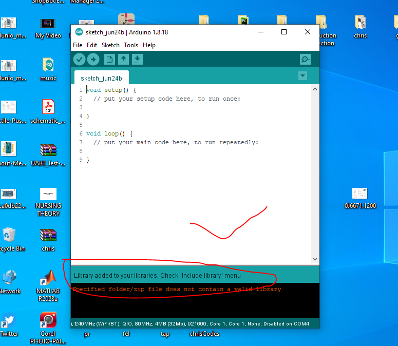
tried to relocate the file and selected it but it won’t work
.png)
giving an error
.png)
so to fix this issue i just ectraxted the whole zipped file and inside the folder i selected
the folder named grbl and then i compress it alone and select it for arduino
.png)
i opened to arduino again and then selected the file again and then it apeared to be working

after successfully done making the installing the firmware in arduino ide so nest is to flash it on arduino board
all i need is to open from tabs to file>> examples>> GRBL >> grblupload
.png)
new window apear to be like this
no modification in codes is needed i just select arduino board and select upload

next i have downloaded a controlling software that we used for laser work process
download direct from link HERE
more about the software visit page HERE
.png)
installing the software
.png)
i opened the software
on the picture i have marked different parts
1. it is rabelled as COM this is where i select communication port between hardware and software
2. this is the boudrate the port will operate on
3. that button is to connect or start the program after connecting usb port
4. this is the navigation bar to control the movement of all axis
5. this working space where design is placed
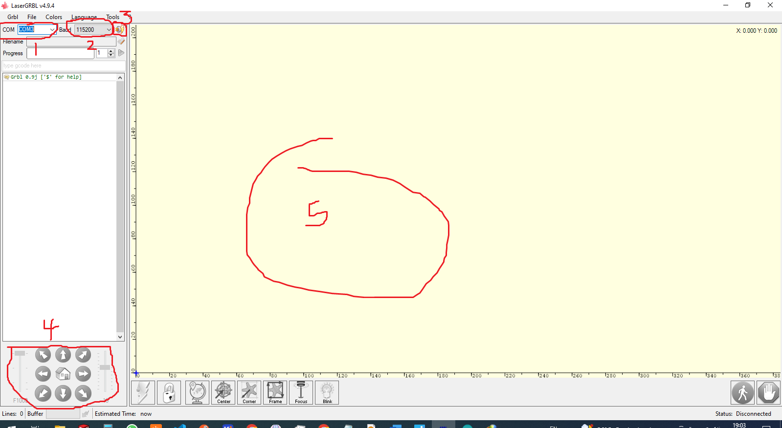
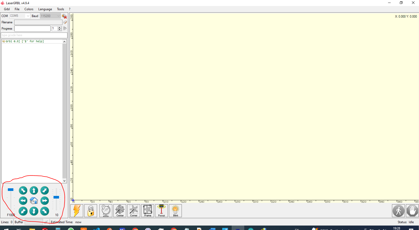
when the controller is not connected the nvigation bar stay grey and cannot be clicked
and when connected they change and can be able to click it
if the board is installed with the firmware the software will automatically recognise it
conclusion
in this assignment of mechanical machine design with my contribution of software and programm by flashing firmware to microcontrollerwhich is great opportunity for the machine by which it helps to integrate between the mechanics and electronics but also mechanics and user
where it can be read from user controller
what i ave learnt from this type of assignment
there's more to learn in this work mechanics automation software programming and electronics controller
so after finnishing the machine design i have gained more skills about cnc controller software from backend of the the controller
to the frontend of the controller,
backend controller as a firmware that handles all processes of the machine and also about frontend controller which is enduser side
it is all about controlling or manipulating all machine axis, and importing design and it generates g-code for the machine
Therefore as well as understood g-code program
that was about software but also i have learn how cnc mechanism works as well as electronics it is concerned
the following video shows how i imported random design and then we started designing and the followed the above mentioned processes