- Project description
- electronic design
- PCB designer and electronics production
- design description
- CAD and 2D&3D design and 3d printing
- programming
- preparing for assembling 3D structure
VENDING MACHINE
A vending machine is an automated machine that provides items such as snacks, beverages,cigarettes, and lottery tickets to consumers after cash, a credit card,
or other forms of payment are inserted into the machine or otherwise made.
The first modern vending machines were developed in England in the early 1880s and dispensed postcards.
Vending machines exist in many countries and, in more recent times, specialized vending machines that provide
less common products compared to traditional vending machine items have been created. more about follow here
FINAL PROJECT DESCRIPTION
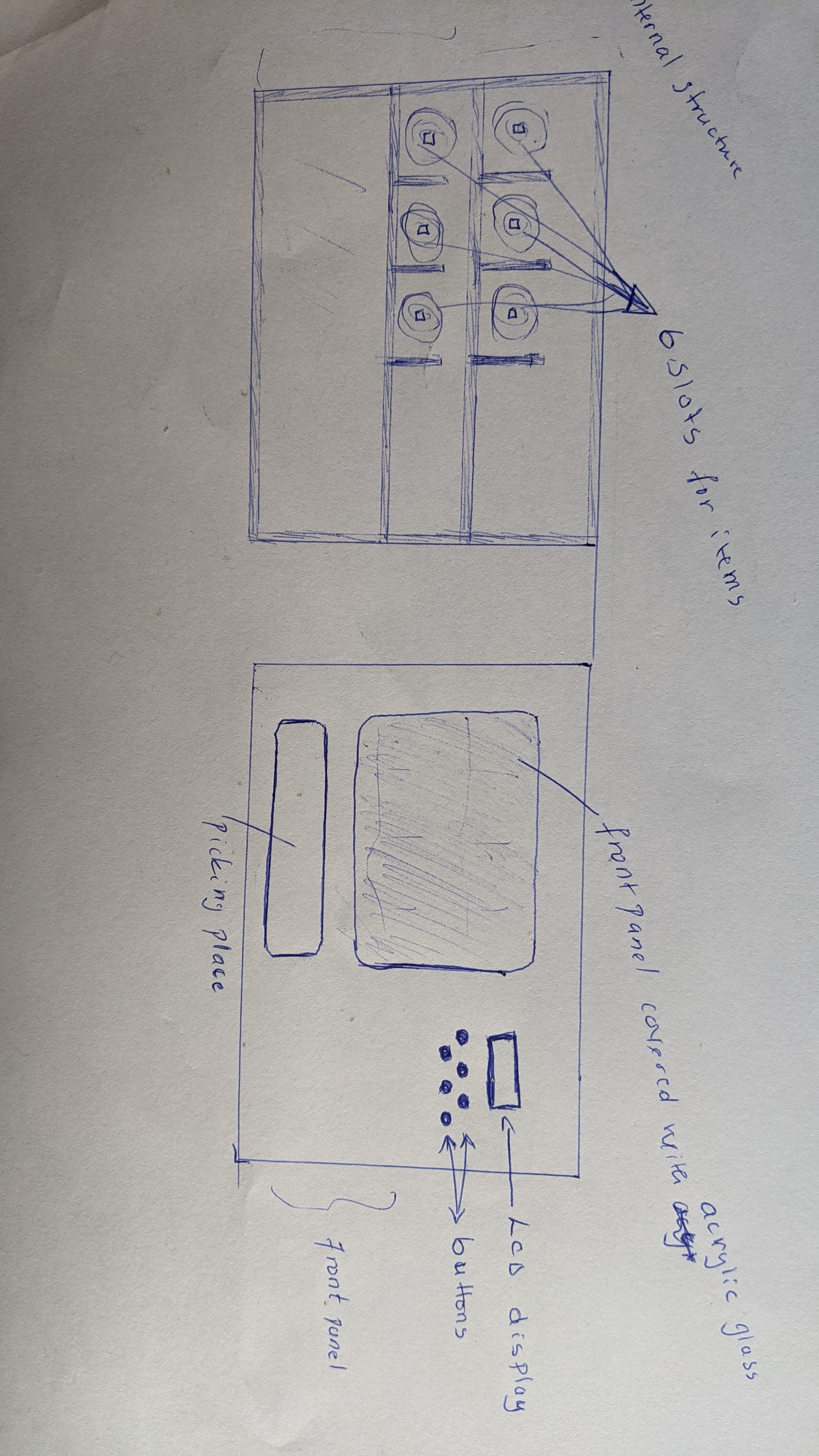
my project is vending machine which has six slot that will be containning different items for celling, the project is mechanicaland electronics it has it is furnitured, plastic, acrylic glass.
in electronics controls it is composed with microcontroller, motor controller(switching mosfet), lcd display, coin detector and power supply.
HOW IT WORKS
when a user needs something from vendor, lets say a snacks, they first push a button by calling an item and will be asked to tap a card to pay and push the button again to get an item,this button is designed and mapped with the place of the items in machine accordingly, though if this button is pressed the corresponding for example snack is going to be picked and come down by mechanism.
PROJECT PLAN AND SKETCH
for the first sketch it shows the front view of the proposed sketch designwhere it shows how everything is ready and aligned on the sketch
by the sketch and planning about the project i started design it in CAD software solidworks
electronic design
for the electronic design i have used kiCad designerand started in schematic designer
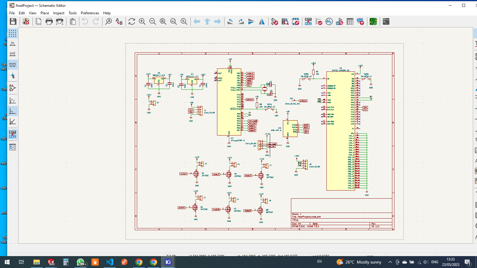
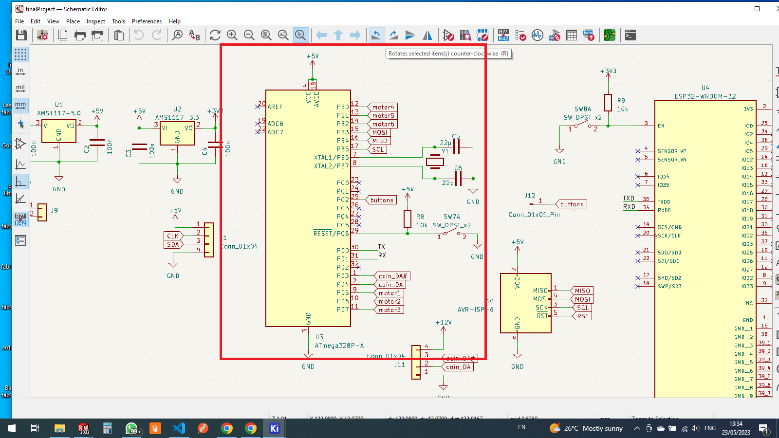
microcotroller atmega 328p section in schematic diagram
another microcontroller used as ESP32

for switching motors i have used mosfet to switch the motors

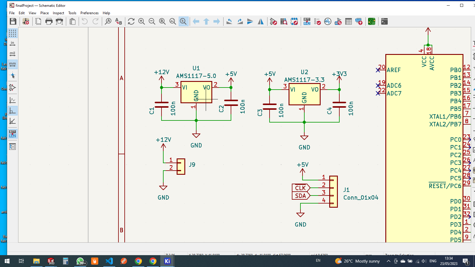
also for powering both microcontrollers there's 5v and 3.3v voltage regulators
ams1117 5 as 5v voltage regulator, and ams1117 3.3 for 3v voltage regulator
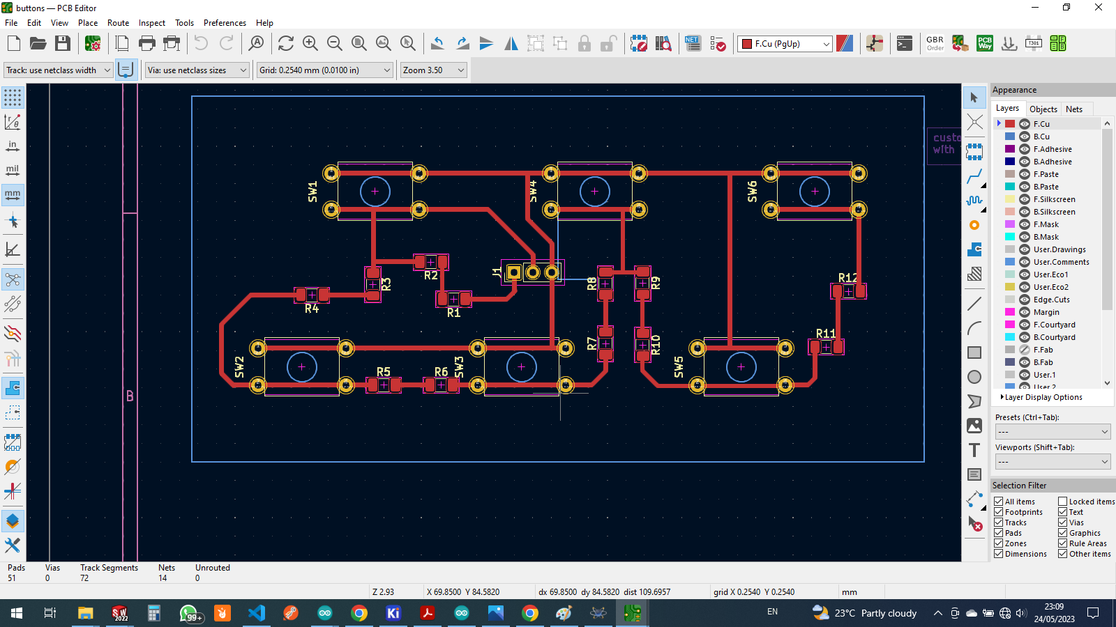
PCB designer and elctronics production
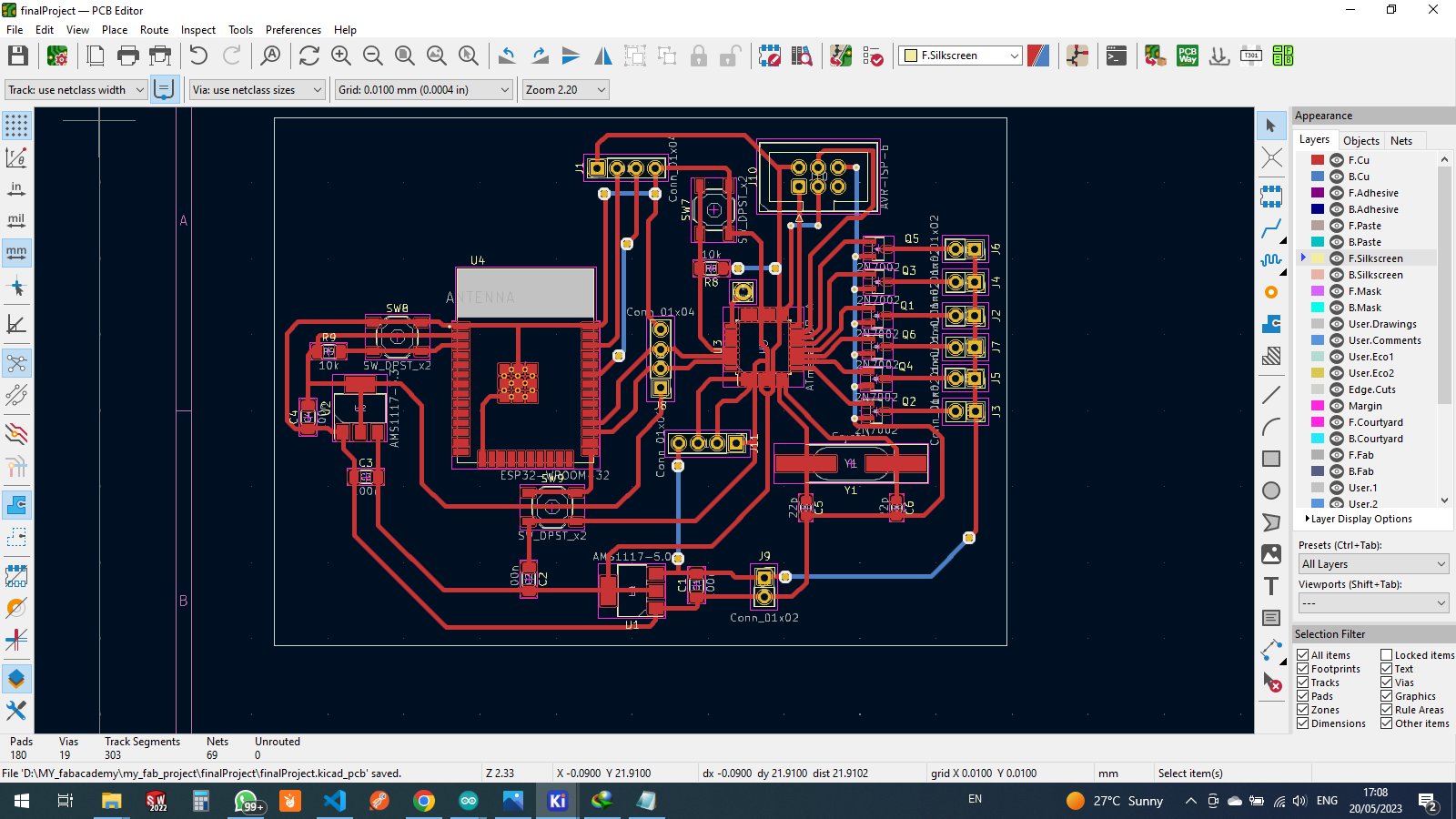
for the PCB i have opened pcb editor clicked on "update pcb button"
arranged all components on the right place and started tracing for signal and power lines
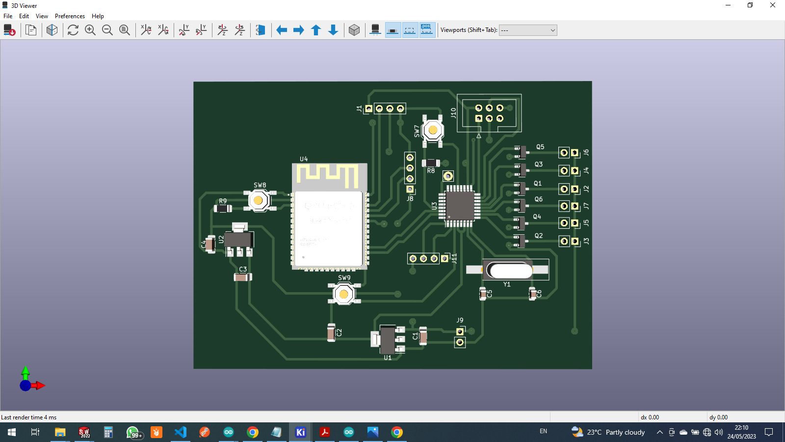
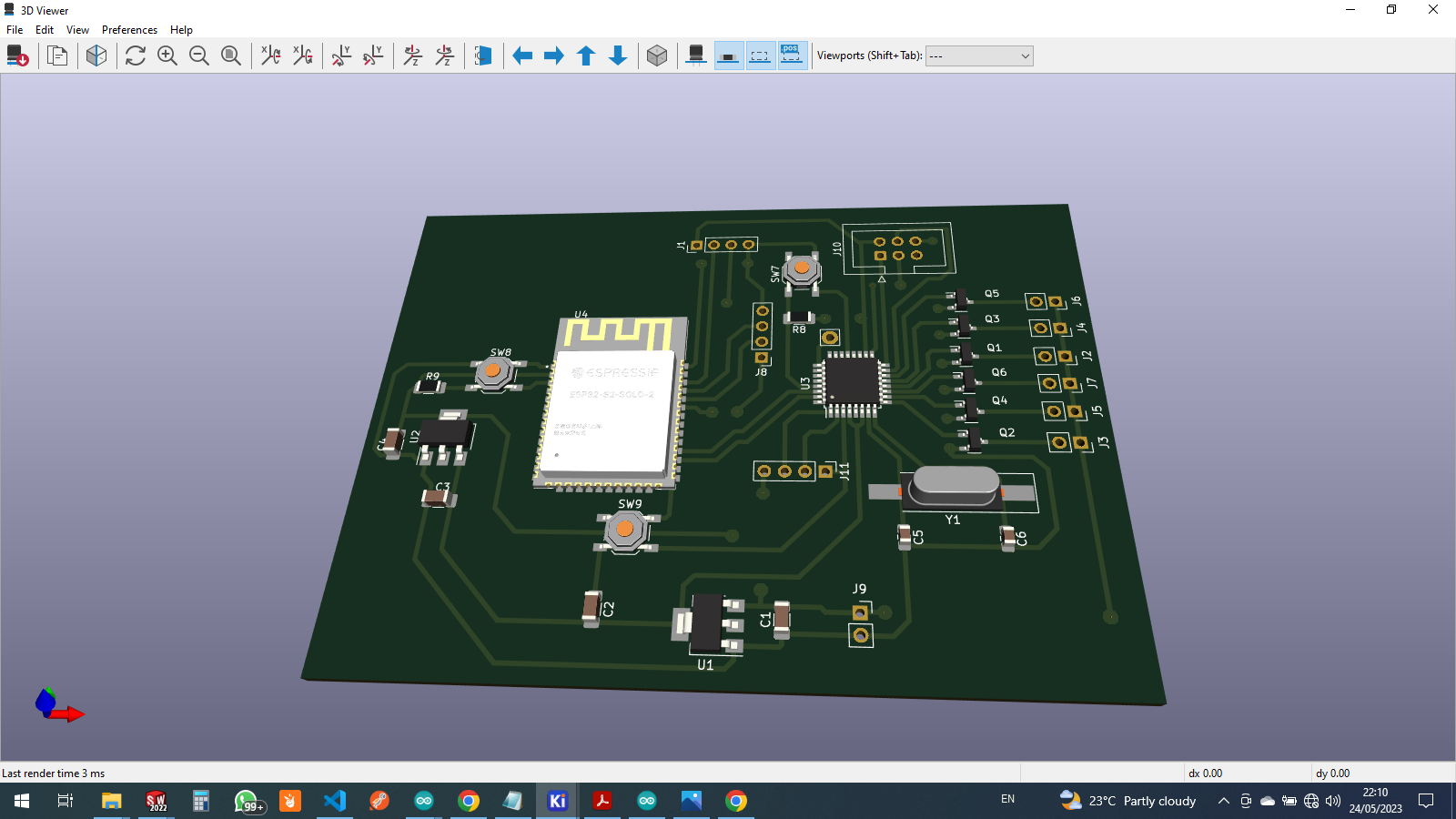
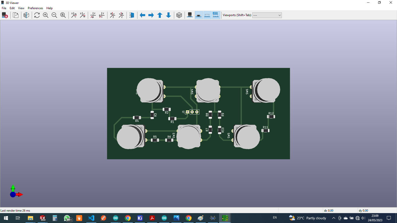
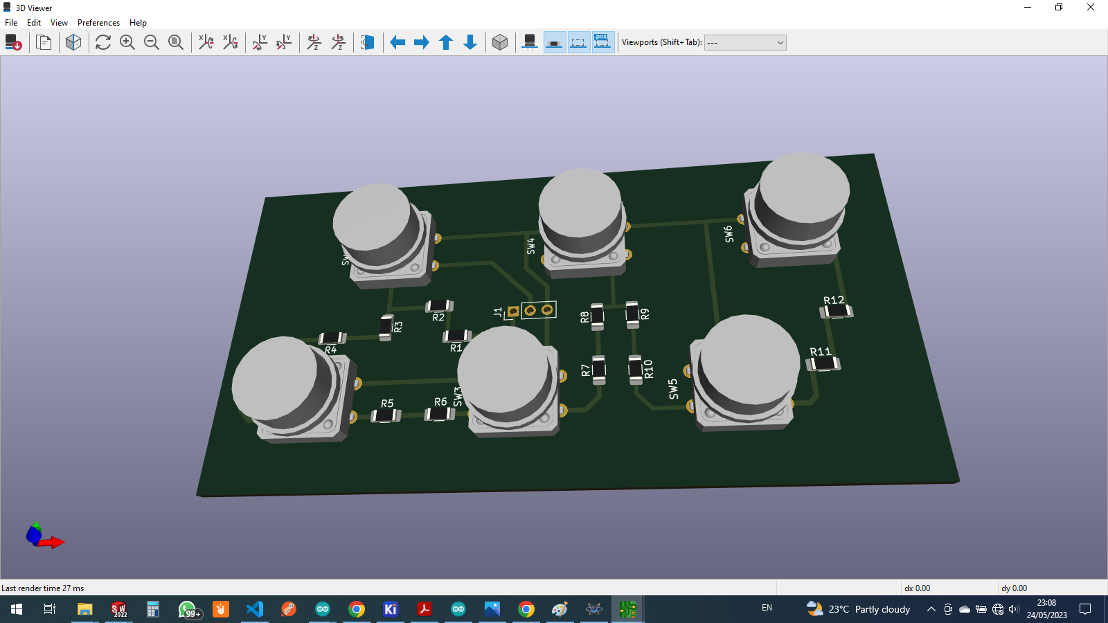
so as we expecting to see it in real world this is how 3d model looks like
for the electronics i has two parts of the projeect one is the one i introduced above as a body or controller
another one is keys or push buttons that will be used to select an items from the machine
at first i designed schematic and then the pcb
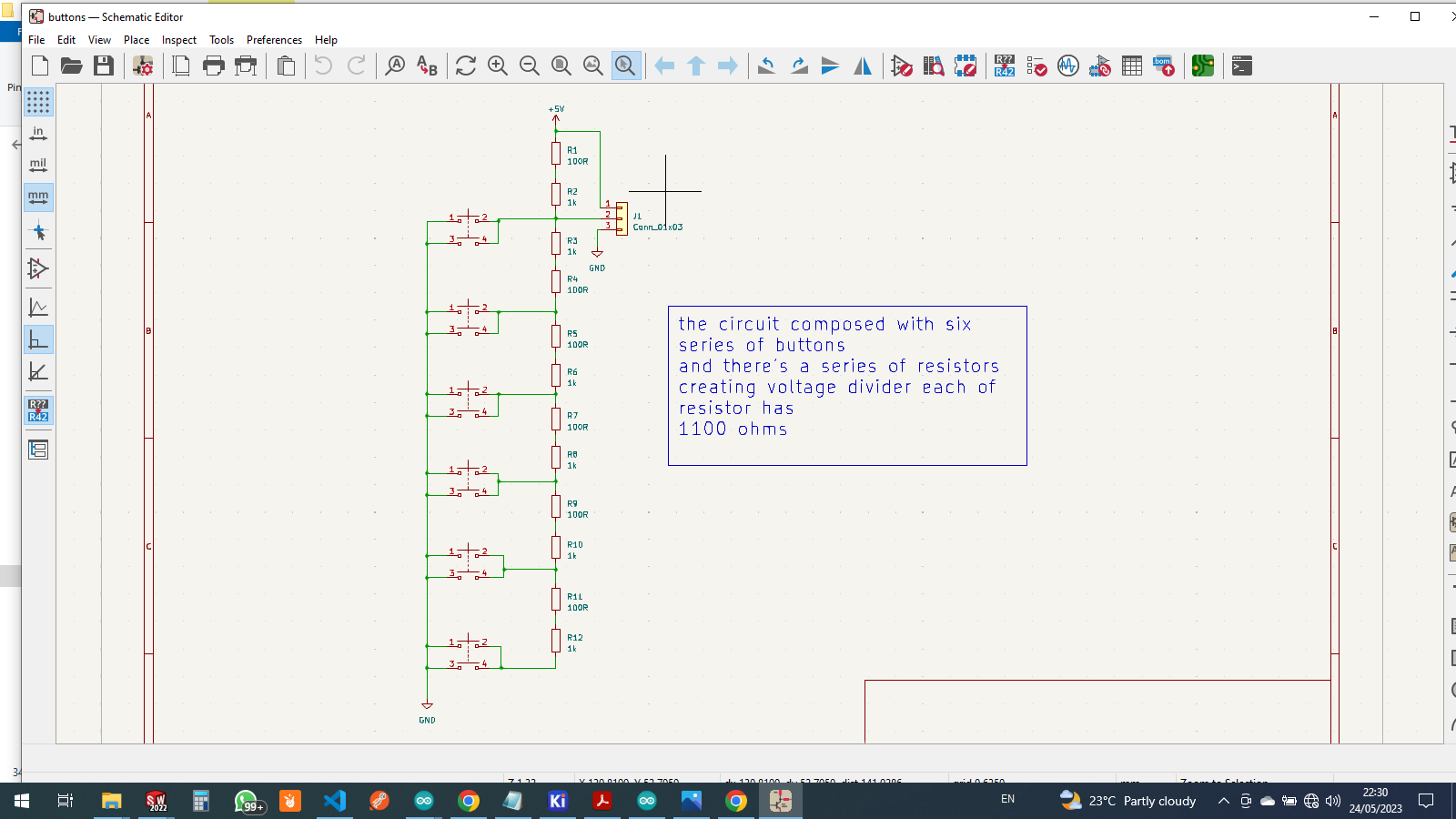
review for the circuit on the top i have vcc 5v on the low gnd so we can make the voltage divider
that may enable us to read different analog input
as it is shown in the image below the current moving as shown in the depending on pressed button

then i open pcb editor and started making arrangement of components and traces
preparing for milling
starting with saving pcb as SVG file from kicad designer so that we import SVG file as we make gcode fileopened the following to generates pcb milling file https://mods.cba.mit.edu/
then before generating the pcb g code file this is the SVG file
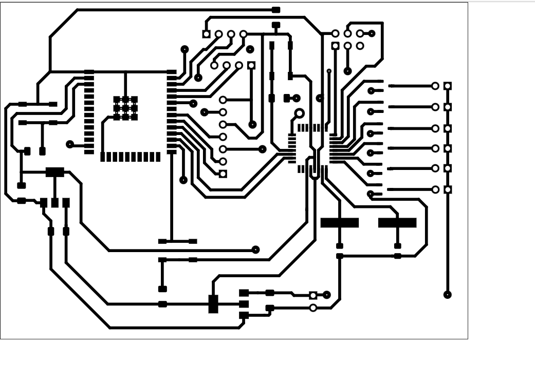
.png)
then to from mods right click i scroll down find SRM-20 (my printer) under PCB SVG

i imported the image i saved as SVG clicked on invert so that the copper trace remain on top
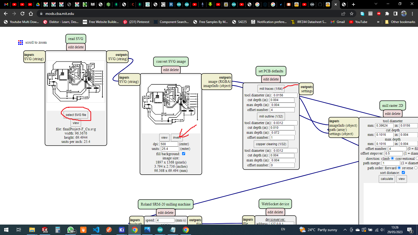
after inverting then i click on mil traces as i am going to mill the pcb
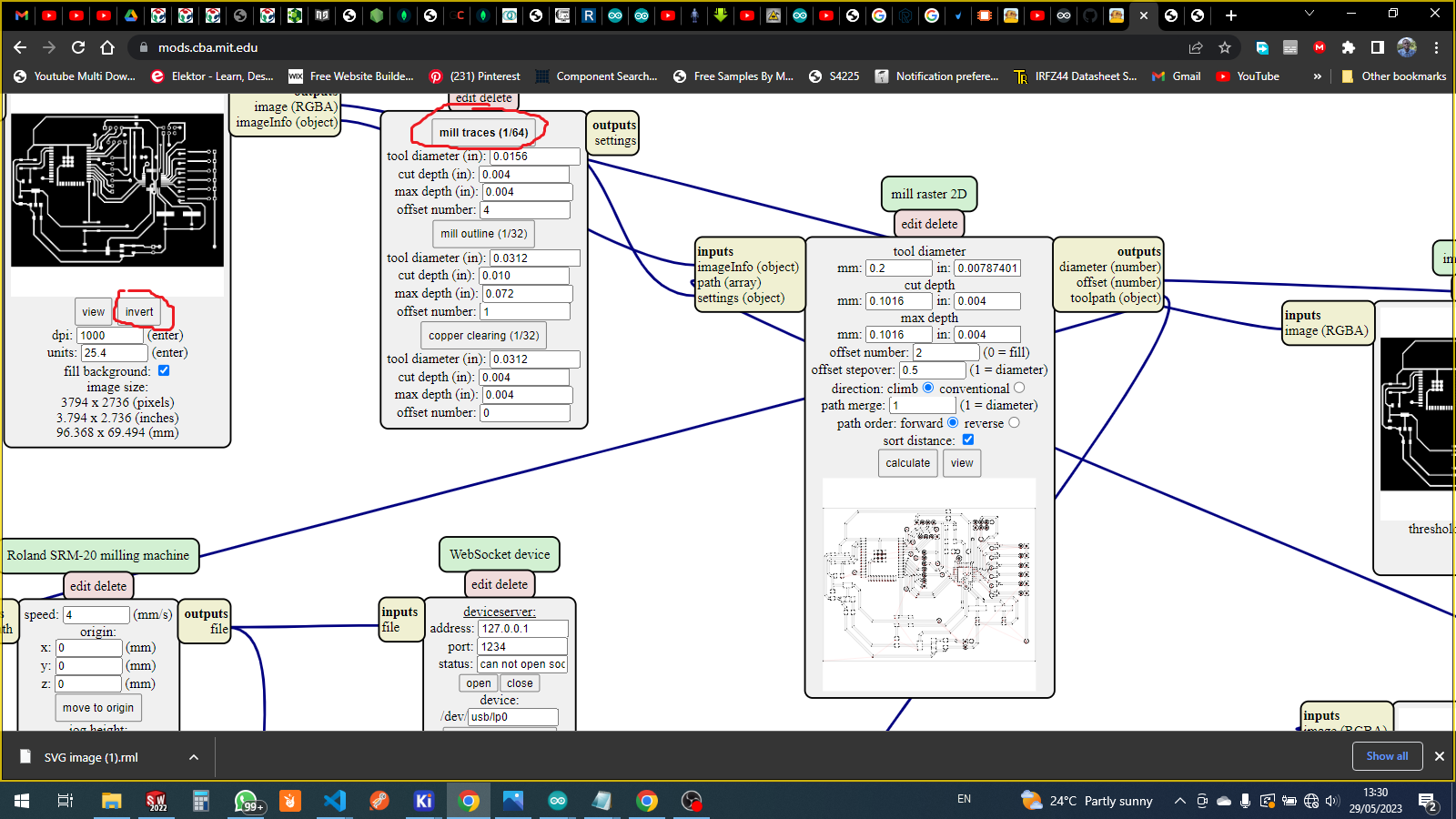
on top i insert the diameter of tool i am goint to use for milling
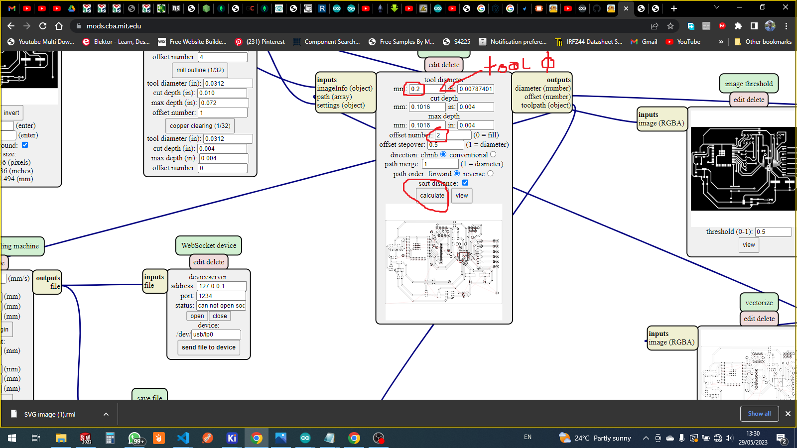
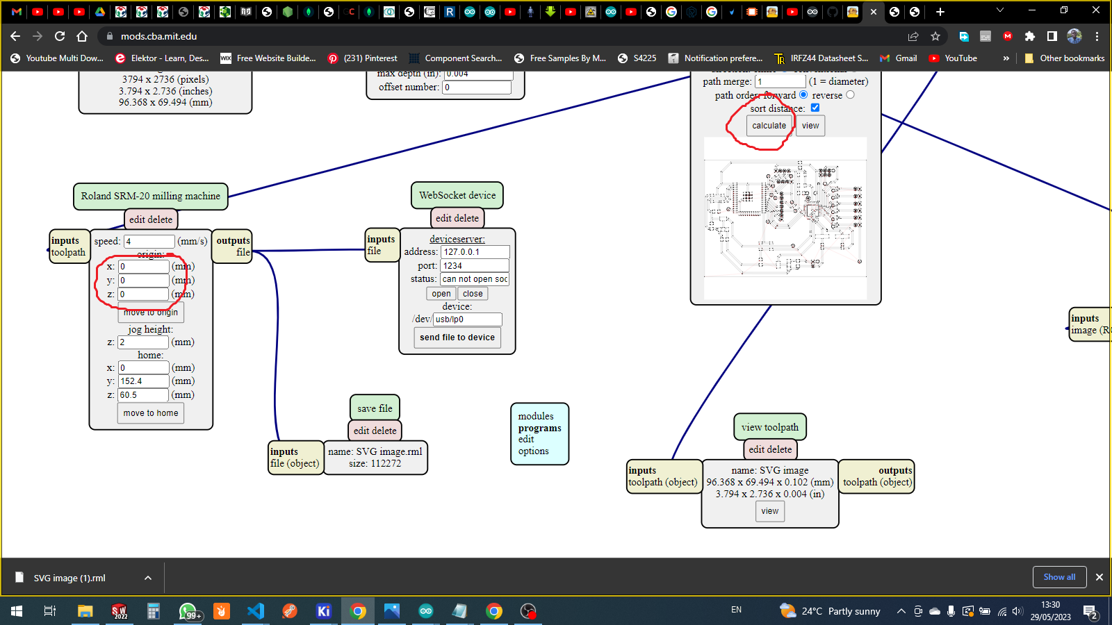
on this part i set the orgin to start from 0 then after setting all those paratmeters i click on calculate to download the g code file
for more about how i prepare for pcb milling LINK HERE from one of the recent Assignment
.png)
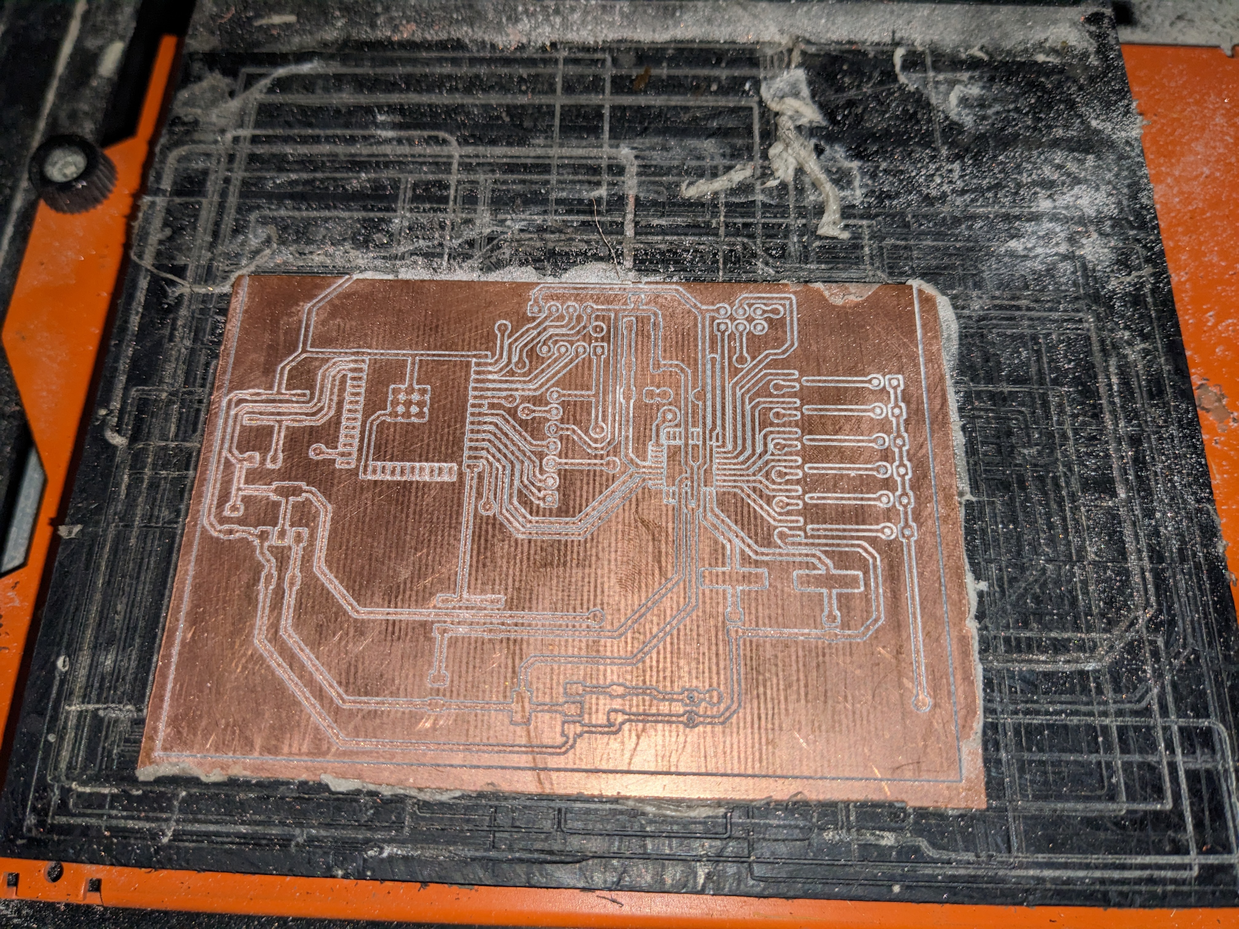
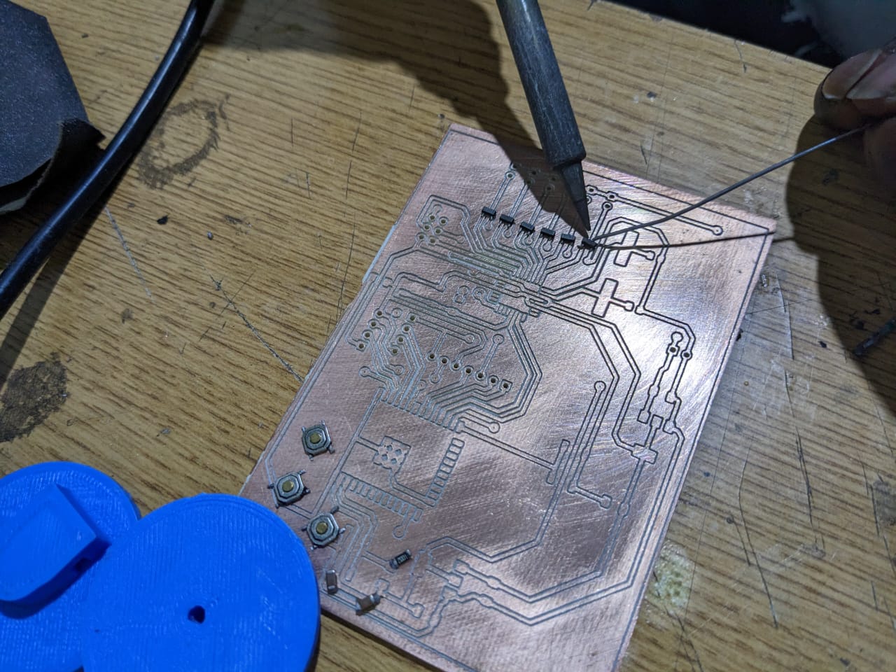
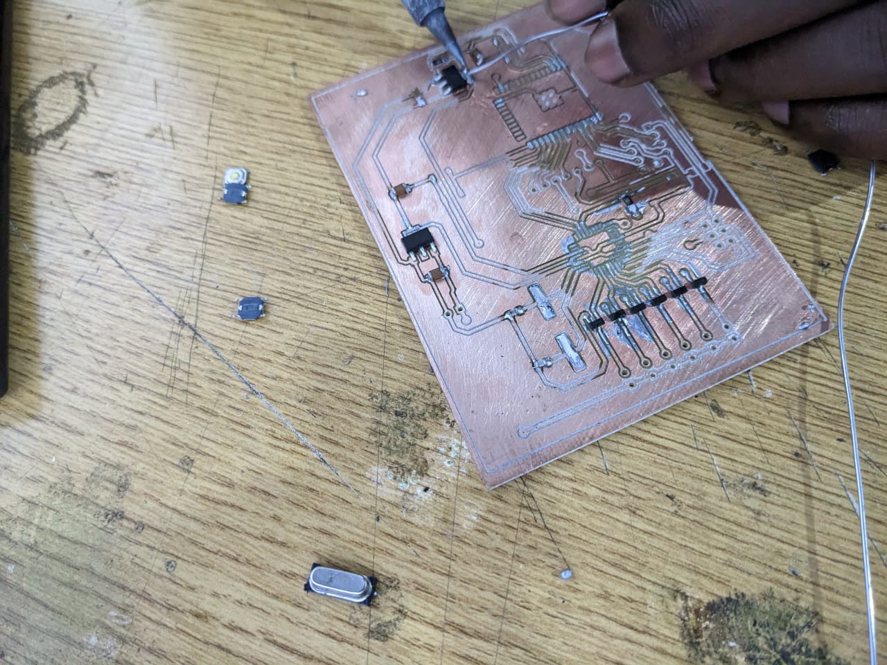
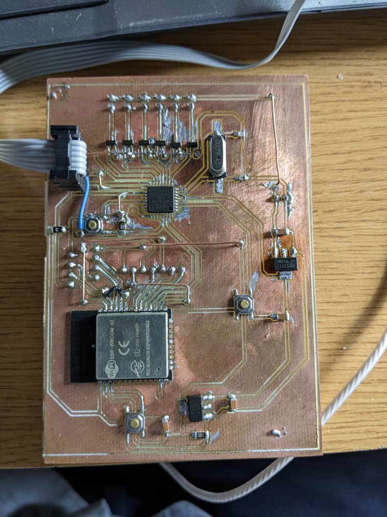
done soldering the whole pcb

design description
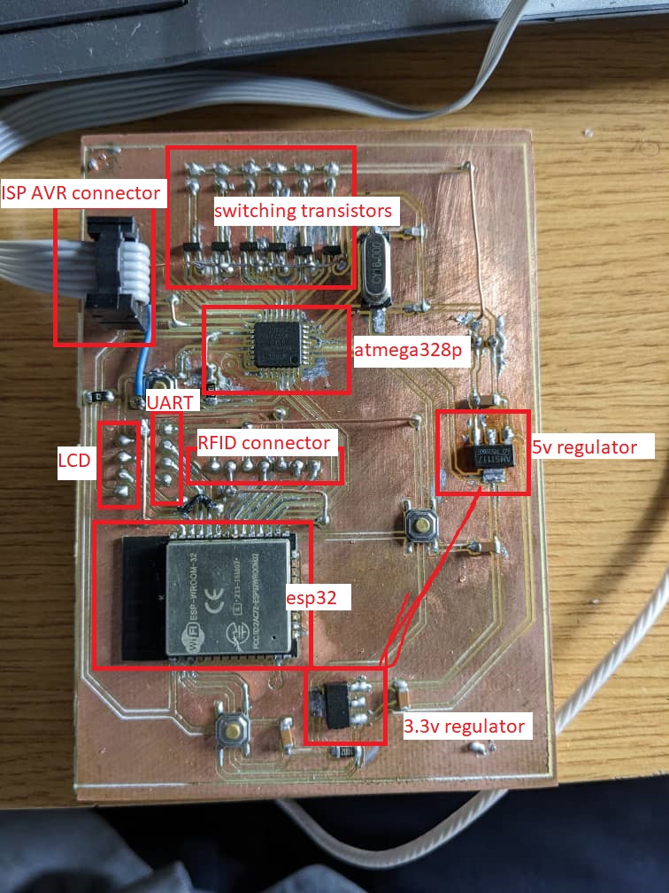
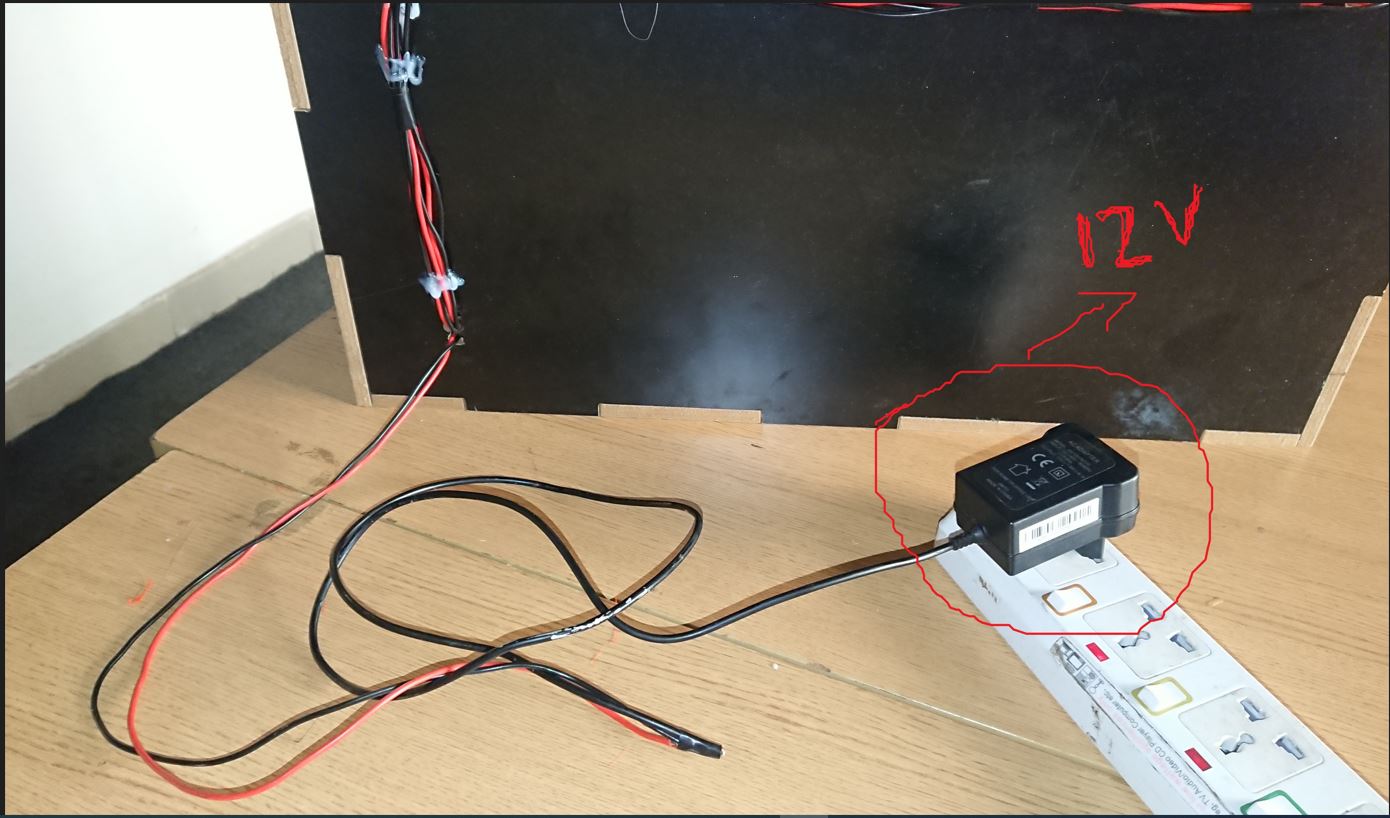
in my design i have power regulation of 5v and 3.3v with the supply voltage of 12v,
and also i have section of microcontroller where i have used two microcontrollers atmega328p and esp32
i also have switching section with six transistors that are used to switch six motors
why i chose 2 different microcontrollers
as it is seen in the project above i have six motors so to avoid conflicts in the design i have chose to use atmega328pto control all six motors and buttons and also the esp32 doesn't have many pins i would be out of pins for esp32 only which i chose use
in my project when i was making project plan because it is powerful
so esp32 is chosen to control lcd display and RFID reader,
and also this system integration would be more easy for me to troubleshoot if there's some issues found in project and easy to relocate the problem origin
here's the integration with RFID
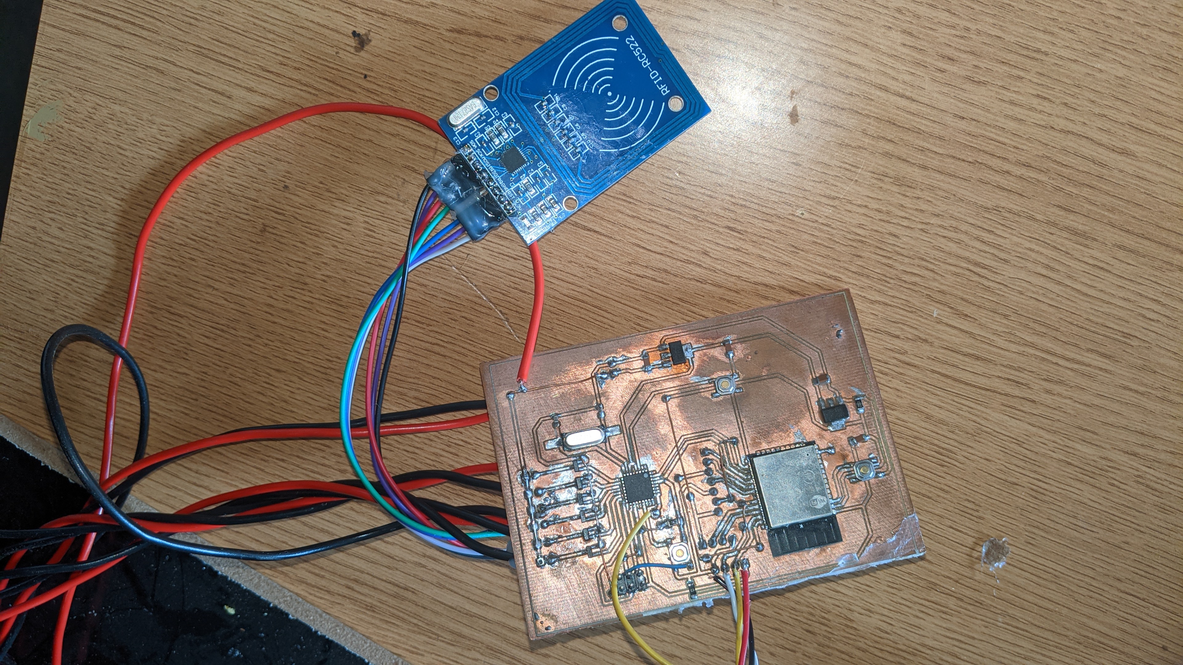
all circuit assembly with all devices are integrated together as shown following all system integration
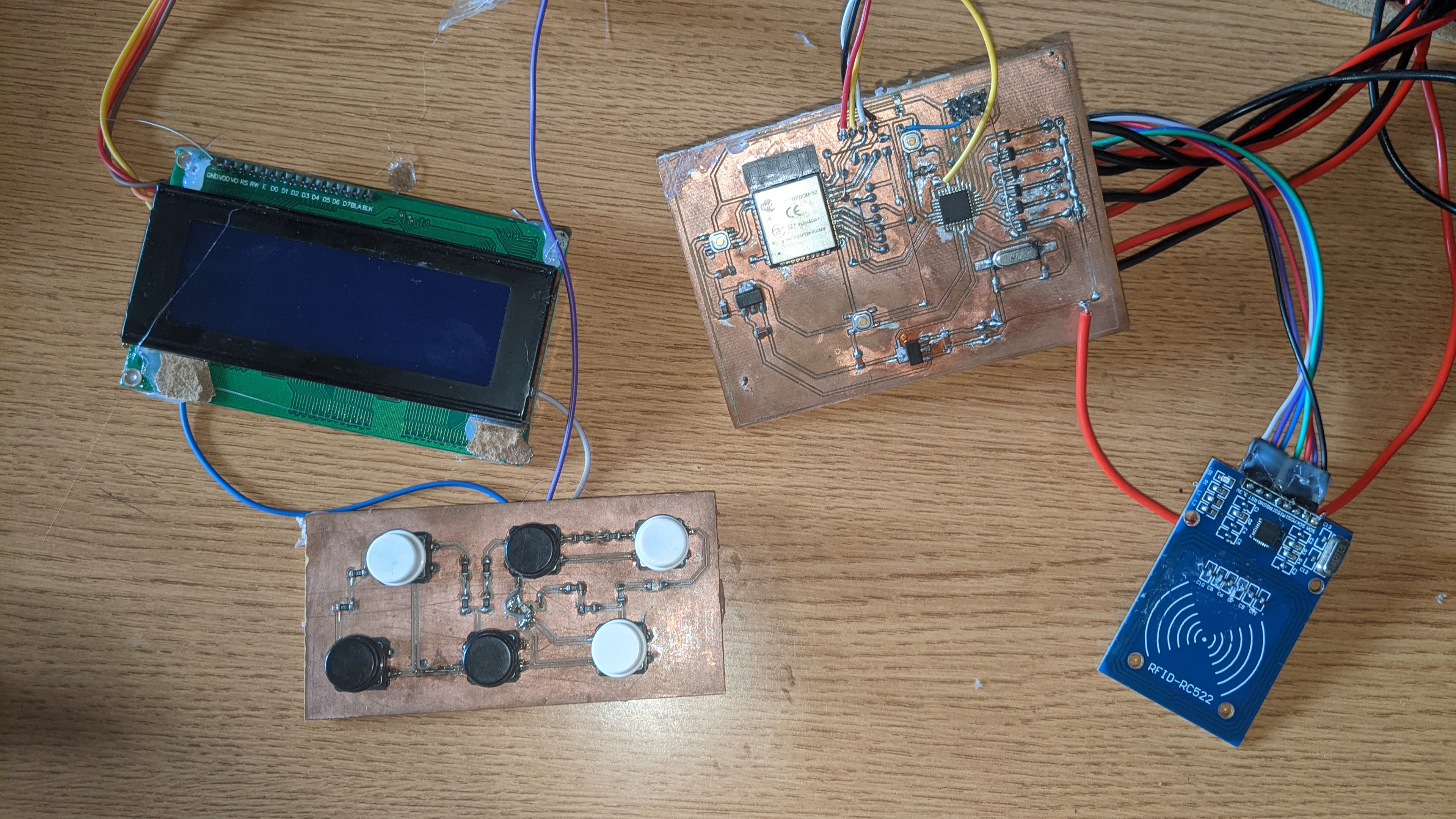
also the whole system is powered with 12v power supply
programming
for the programming codes i used arduino ide, as i have used two microcontrollers atmega328p and esp-wromm-32as the project implies with tasks inside the project processing
the atmega328p controls dc motors and read buttons then the esp32 handdle the rest
like lcd connecting to server and reading rfid tag
the following codes are for the atmega328p
              #include

                int dly = 2000;
                int motorStatus;
                int val;
                int rotdelay = 2000;
                int buttonStatus;
                int dl = 500;

                  ///////////////
                  int m1 = 5;
                  int m2 = 6;
                  int m3 = 7;
                  int m4 = 8;
                  int m5 = 9;
                  int m6 = 10;

                  //////////////
                void setup() {

                  pinMode(A0, INPUT);
                  pinMode(m1, OUTPUT);
                  pinMode(m2, OUTPUT);
                  pinMode(m3, OUTPUT);
                  pinMode(m4, OUTPUT);
                  pinMode(m5, OUTPUT);
                  pinMode(m6, OUTPUT);

                Serial.begin(112500);
                while (!Serial) continue;


                }

                void loop() {

                /////////////button selecting///////////////

                int val = analogRead(A0);


                if (val >= 580 && val<= 620){
                  buttonStatus = 1;
                  serialpush();
                  Serial.println("button1 selected");
                  delay(dl);
                }

                if (val >= 650 && val<= 680){
                   buttonStatus = 2;
                   serialpush();
                   Serial.println("button2 selected");
                   delay(dl);
                }

                if (val >= 700 && val<= 715){
                    buttonStatus = 3;
                    serialpush();
                    Serial.println("button3 selected");
                    delay(dl);
                }

                if (val >= 760 && val<= 775){
                    buttonStatus = 4;
                    serialpush();
                    Serial.println("button4 selected");
                  delay(dl);
                }

                if (val >= 830 && val<= 850){
                    buttonStatus = 5;
                    serialpush();
                    Serial.println("button5 selected");
                  delay(dl);
                }

                if (val >= 915 && val<= 935){
                    buttonStatus = 6;
                    serialpush();
                    Serial.println("button6 selected");
                  delay(dl);
                }

                ///////////////////////selecting and switching motors/////////////////////////////////////////

                 if (Serial.available()){
                  serialpull();
                    if (motorStatus== 1) {
                      void motor1();
                    }
                  }


                  if (Serial.available()){
                    if (motorStatus== 2) {
                      void motor2();
                    }
                  }


                  if (Serial.available()){
                    if (motorStatus== 3) {
                      void motor3();
                    }
                  }


                  if (Serial.available()){
                    if (motorStatus== 4) {
                      void motor4();
                    }
                  }

                  if (Serial.available()){
                    if (motorStatus== 5) {
                      void motor5();
                    }
                  }


                  if (Serial.available()){
                    if (motorStatus== 6) {
                      void motor6();
                    }
                  }


                ////////////////////////////////////////////////////////////////
                }


                void serialpush(){
                  StaticJsonDocument<200> doc;
                  doc["buttonStatus"] = buttonStatus;
                  // Send the JSON document over the "link" serial port
                  serializeJson(doc, Serial);
                  // Wait
                  delay(2000);

                }


                void serialpull(){
                  StaticJsonDocument<200> doc;
                  doc["motorStatus"] = motorStatus;
                  deserializeJson(doc, Serial);
                   delay(2000);
                }


                //////////////////////////////////////////

                void motor1(){
                   digitalWrite(m1, HIGH);
                   delay(rotdelay);
                    digitalWrite(m1, LOW);
                }

                void motor2(){
                     digitalWrite(m2, HIGH);
                   delay(rotdelay);
                   digitalWrite(m2, LOW);
                }
                void motor3(){
                     digitalWrite(m3, HIGH);
                   delay(rotdelay);
                    digitalWrite(m3, LOW);
                }
                void motor4(){
                     digitalWrite(m4, HIGH);
                   delay(rotdelay);
                    digitalWrite(m4, LOW);
                }
                void motor5(){
                     digitalWrite(m5, HIGH);
                   delay(rotdelay);
                    digitalWrite(m5, LOW);
                }
                void motor6(){
                     digitalWrite(m6, HIGH);
                   delay(rotdelay);
                    digitalWrite(m6, LOW);
                }
the following codes are for esp32
#include
#include
#include
LCD_I2C lcd(0x27, 20, 4);
#define RST_PIN 4 // Configurable, see typical pin layout above
#define SS_PIN 5 // Configurable, see typical pin layout above
MFRC522 mfrc522(SS_PIN, RST_PIN); // Create MFRC522 instance.
MFRC522::MIFARE_Key key;
#define RXp2 16
#define TXp2 17
uint32_t CardBalance = 0;
uint32_t total_cost=0;
String Card="";
uint32_t Card_Balance=0;
int progress=0, stage=0;
const unsigned long period = 1000;
float volume=0.0;
uint32_t unit_cost[]={200,300,400,500,600,700};
String item;
String prod1 = "choco";
String prod2 = "teabag";
String prod3 = "coffee";
String prod4 = "snack";
String prod5 = "candy";
String prod6 = "nut";
const char* ssid = "SOV36";
const char* password = "123456780";
String machine = "1A2B3C";
int cost;
String product;
int servstatus;
int buttonStatus;
int motorStatus;
int serdl = 60;
int32_t value;
void setup() {
// put your setup code here, to run once:
Serial.begin(115200);
Serial2.begin(115200, SERIAL_8N1, RXp2, TXp2);
WiFi.begin(ssid, password);
SPI.begin();
lcd.begin();
lcd.backlight();
mfrc522.PCD_Init(); // Init MFRC522 card
for (byte i = 0; i < 6; i++) {
key.keyByte[i] = 0xFF;
}
// Serial.println(F("tap your card"));
}
void loop() {
tap();
while (Serial2.available()){
serialpull();
while(buttonStatus!=0 || buttonStatus!=NULL){
stage=1;
Serial.println(buttonStatus);
total_cost= unit_cost[buttonStatus-1];
Serial.println("item cost= "+String(total_cost));
while(stage==1){
checkcardinfo();
}
if(CardBalance>=total_cost){
Serial.print("nice");}
else{DenielScreen();
}
buttonStatus=NULL;
motorStatus=NULL;
CardBalance=NULL;
total_cost=NULL;
}
}
}
void DenielScreen(){
Serial.println("insufficient balance");
lcd.clear();
lcd.setCursor(0,0);
lcd.print("insufficient bal");
}
void serialpush(){
Serial2.println(motorStatus);
// Wait
//delay(2000);
Serial.println("serial push stage end");
}
void serialpull(){
if (Serial2.available()){
StaticJsonDocument<300> doc;
DeserializationError err = deserializeJson(doc, Serial2);
if (err == DeserializationError::Ok)
{
buttonStatus = doc["buttonStatus"].as();
Serial.println(buttonStatus);
delay(2000);
}
}
}
void serialpull1(){
if (Serial2.available()){
Serial.println(Serial2.read());
}
}
//void cardRequest(){
//Serial.print("tap a card");
//
//
// lcd.clear();
// lcd.setCursor(2, 1);
// lcd.print("TAP CARD TO PAY");
// lcd.setCursor(5, 2);
// lcd.print(product);
//}
////////////////////////////////////////////////////////////////////////////////////
/* checking new card information and storing them */
///////////////////////////////////////////////////////////////////////////////////////
void checkcardinfo(){
// Reset the loop if no new card present on the sensor/reader. This saves the entire process when idle.
if ( ! mfrc522.PICC_IsNewCardPresent())
return;
// Select one of the cards
if ( ! mfrc522.PICC_ReadCardSerial())
return;
Card="";
for (byte i = 0; i < mfrc522.uid.size; i++)
{
Card+=String(mfrc522.uid.uidByte[i],HEX);
Card.toUpperCase();
}
Serial.println ("new card = "+String(Card));
// screen();
// In this sample we use the second sector,
// that is: sector #1, covering block #4 up to and including block #7
byte sector = 1;
byte valueBlockB = 6;
byte trailerBlock = 7;
MFRC522::StatusCode status;
byte buffer[18];
byte size = sizeof(buffer);
// Authenticate using key A
status = mfrc522.PCD_Authenticate(MFRC522::PICC_CMD_MF_AUTH_KEY_A, trailerBlock, &key, &(mfrc522.uid));
if (status != MFRC522::STATUS_OK) {
Serial.print(F("PCD_Authenticate() failed: "));
Serial.println(mfrc522.GetStatusCodeName(status));
return;
}
byte trailerBuffer[] = {
255, 255, 255, 255, 255, 255, // Keep default key A
0, 0, 0,
0,
255, 255, 255, 255, 255, 255}; // Keep default key B
mfrc522.MIFARE_SetAccessBits(&trailerBuffer[6], 0, 6, 6, 3);
status = mfrc522.MIFARE_Read(trailerBlock, buffer, &size);
if (status != MFRC522::STATUS_OK) {
Serial.print(F("MIFARE_Read() failed: "));
Serial.println(mfrc522.GetStatusCodeName(status));
return;
}
// Check if it matches the desired access pattern already;
// because if it does, we don't need to write it again...
if ( buffer[6] != trailerBuffer[6]
|| buffer[7] != trailerBuffer[7]
|| buffer[8] != trailerBuffer[8]) {
// They don't match (yet), so write it to the PICC
Serial.println(F("Writing new sector trailer..."));
status = mfrc522.MIFARE_Write(trailerBlock, trailerBuffer, 16);
if (status != MFRC522::STATUS_OK) {
Serial.print(F("MIFARE_Write() failed: "));
Serial.println(mfrc522.GetStatusCodeName(status));
return;
}
}
// Authenticate using key B
status = mfrc522.PCD_Authenticate(MFRC522::PICC_CMD_MF_AUTH_KEY_B, trailerBlock, &key, &(mfrc522.uid));
if (status != MFRC522::STATUS_OK) {
Serial.print(F("PCD_Authenticate() failed: "));
Serial.println(mfrc522.GetStatusCodeName(status));
return;
}
// Show the new value of valueBlockB
status = mfrc522.MIFARE_GetValue(valueBlockB, &value);
CardBalance=value;
if (status != MFRC522::STATUS_OK) {
Serial.print(F("mifare_GetValue() failed: "));
Serial.println(mfrc522.GetStatusCodeName(status));
return;
}
Serial.println("card balance = "+String(CardBalance));
Serial.println();
if(CardBalance>=total_cost){
/////////////////////////////////////////////////
status = mfrc522.MIFARE_Decrement(valueBlockB, total_cost);//rest cost
if (status != MFRC522::STATUS_OK) {
Serial.print(F("MIFARE_Decrement() failed: "));
Serial.println(mfrc522.GetStatusCodeName(status));
return;
}
status = mfrc522.MIFARE_Transfer(valueBlockB);
if (status != MFRC522::STATUS_OK) {
Serial.print(F("MIFARE_Transfer() failed: "));
Serial.println(mfrc522.GetStatusCodeName(status));
return;
}
// Show the new value of valueBlockB
status = mfrc522.MIFARE_GetValue(valueBlockB, &value);
Serial.println("new balance= "+String(value));
if (status != MFRC522::STATUS_OK) {
Serial.print(F("mifare_GetValue() failed: "));
Serial.println(mfrc522.GetStatusCodeName(status));
return;
}
////////////////////////////////
motorStatus=buttonStatus;
product = ("item"+String(buttonStatus));
Serial.println("motor "+String(motorStatus));
serialpush();
serialpull1();
// sendToserver();
balanceScreen();
delay(serdl);
}else{
DenielScreen();
}
mfrc522.PCD_StopCrypto1();
stage=0;
}
void tap(){
lcd.clear();
if (product == "1"){item = prod1;}
else if(product == "2"){item = prod2;}
else if(product == "3"){item = prod3;}
else if(product == "4"){item = prod4;}
else if(product == "5"){item = prod5;}
else if(product == "6"){item = prod6;}
// else {item = NULL;}
lcd.setCursor(4,1);
lcd.print("tap card");
lcd.setCursor(3,2);
lcd.print("pick a product");
lcd.setCursor(3,3);
lcd.print(item);
}
void balanceScreen(){
lcd.clear();
lcd.setCursor(0,0);
lcd.print("balance "+String(CardBalance));
lcd.setCursor(0,1);
lcd.print("new_bal "+String(value));
lcd.setCursor(0,2);
lcd.print("card "+String(Card));
lcd.setCursor(0,3);
lcd.print("price "+String(total_cost));
delay(3000);
}
problem rising while trying to upload my codes, shows an error over and over while trying upload to the atmega328p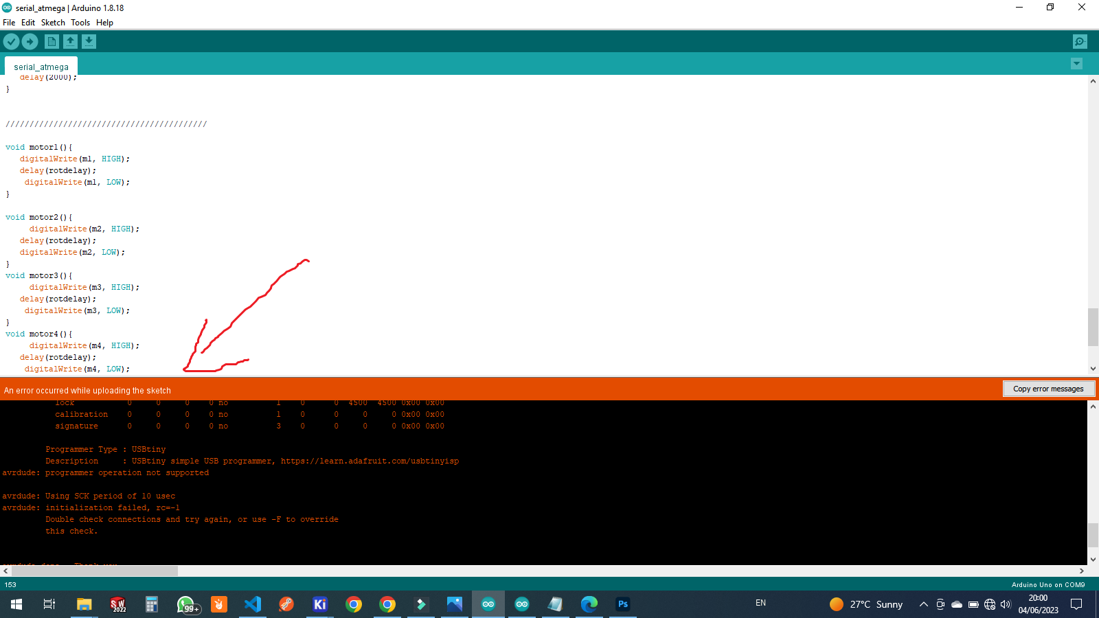 error
errortrying to look for an error i searched on internet different sites but can't find a solution
meanwhile i started checking my soldering on pcb and and connections checked but my connection was okay
so then after i realized that i forgot someting on my pcb while designing
if you noticed i forgot to connect reset pin from ISP header for programmer which is not connected from anywhere
 error
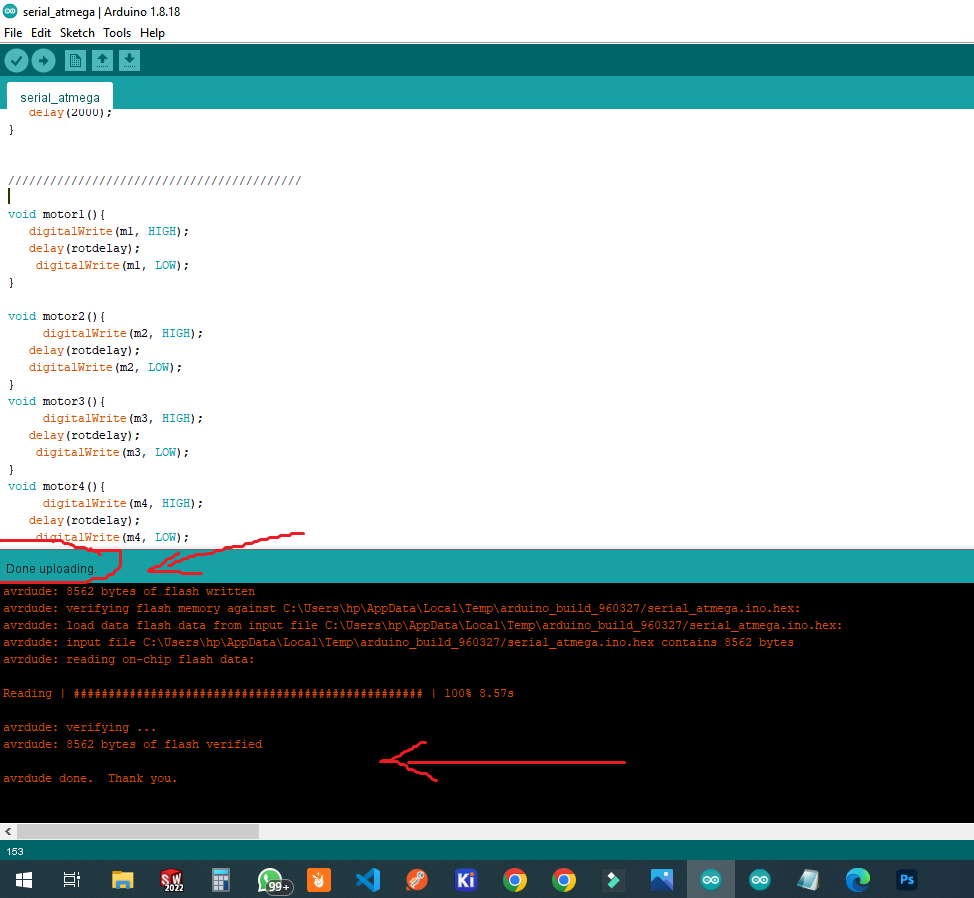
errori have fixed the problem and the codes uploaded successfull and also included original pcb files with fixed issues
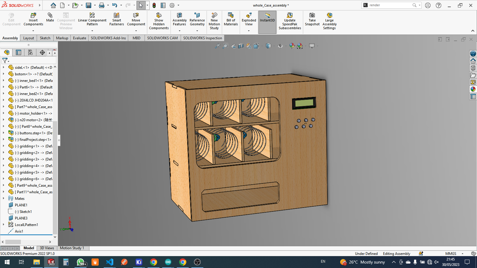
CAD and 2D&3D design and 3d printing
for this part of the project it is CAD design for 3d and 2d design and also modeling of whole designfor inspecting the design
so i also make the assembling here where i deal with machining (cnc)
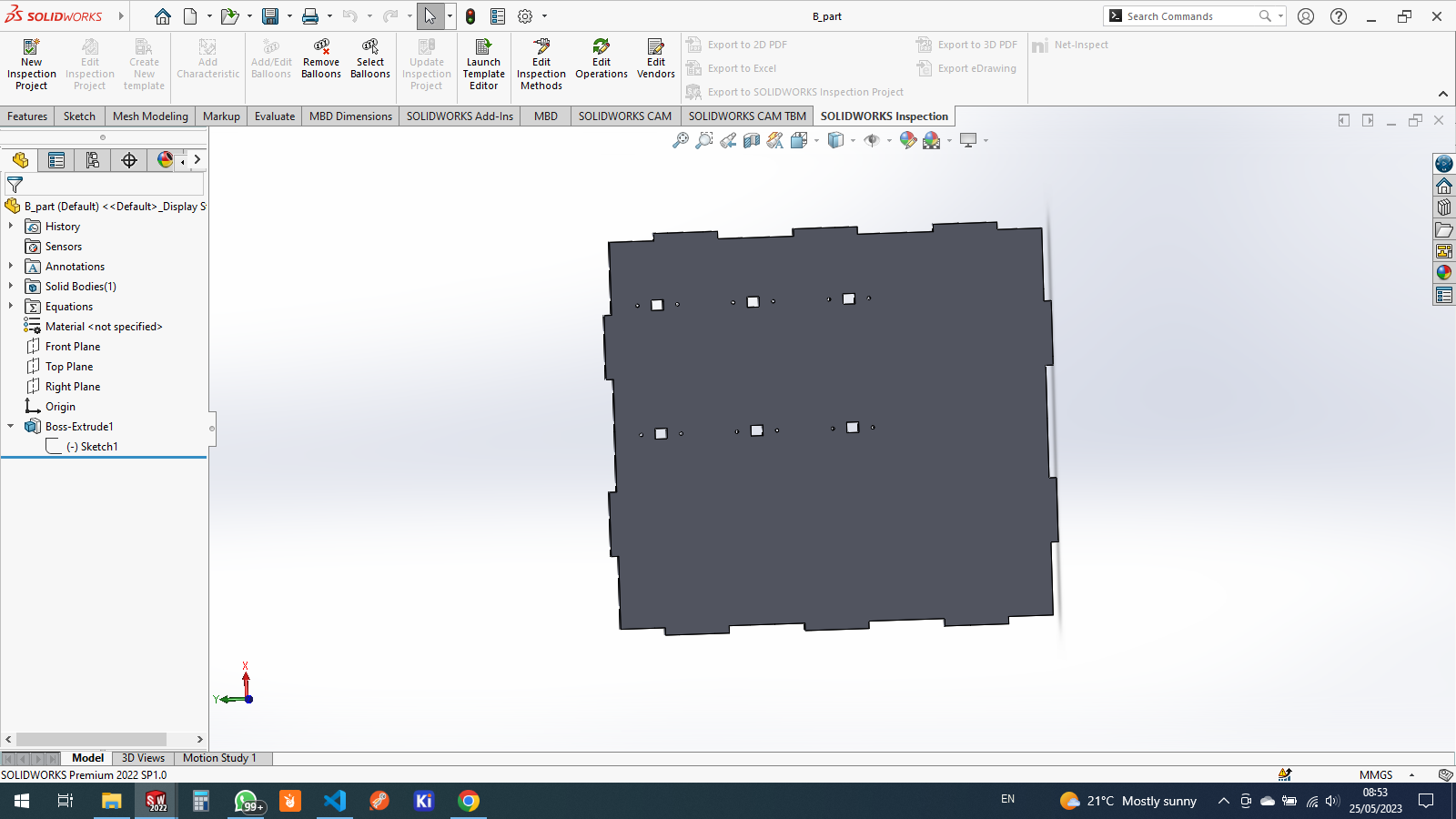
i started making 2d sketch of some parts of the case
this is the back side of the case and the holes in it is the slot of dc motors

the extruded and 3d design
and also this is the top side designed
this the 3d model if top side
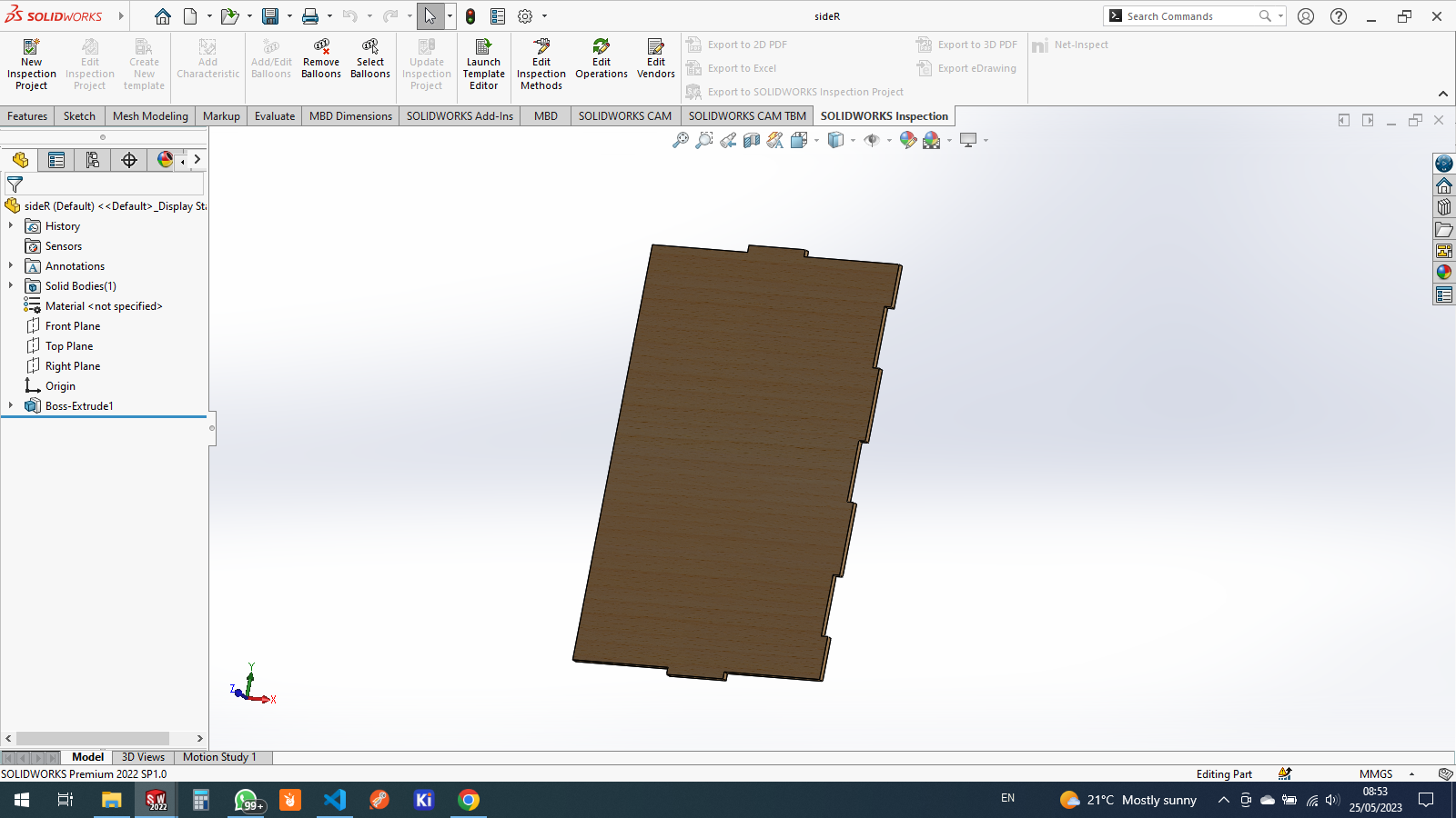
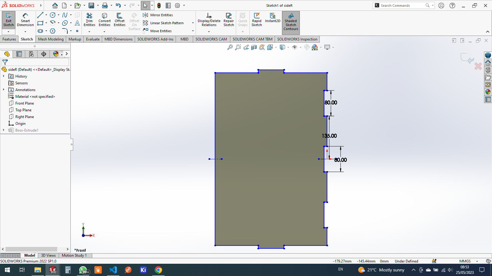
and this is the side part of the case and it is also similar to the other side

the 3d view model

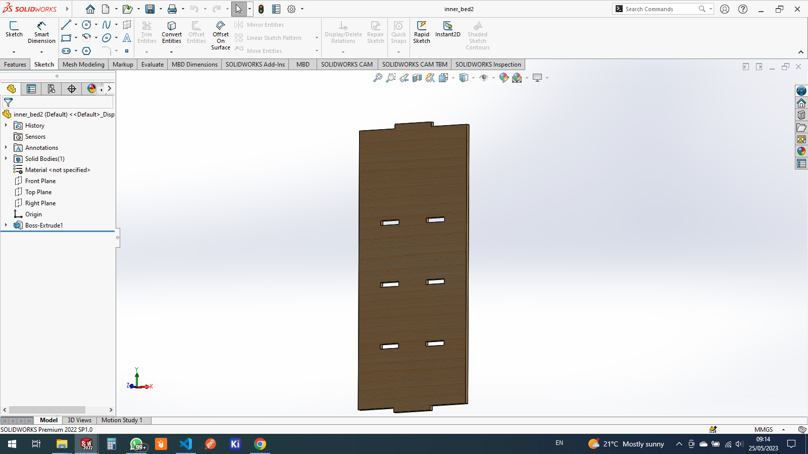
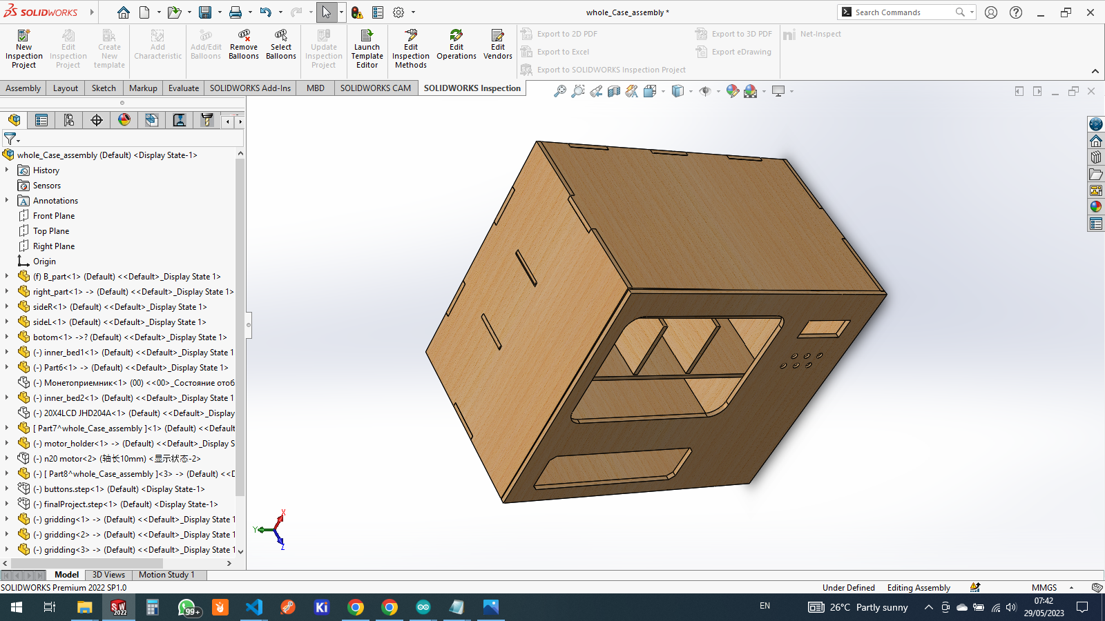
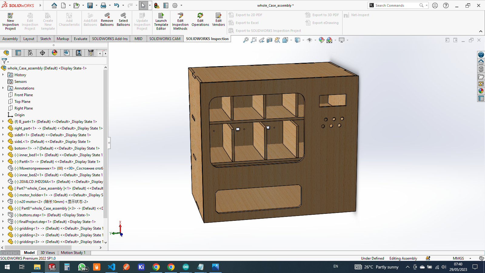
for the whole machine as it will be storing different items i designed the inside 2 parts to hold all items where they will be standing
so here is the sketch of it
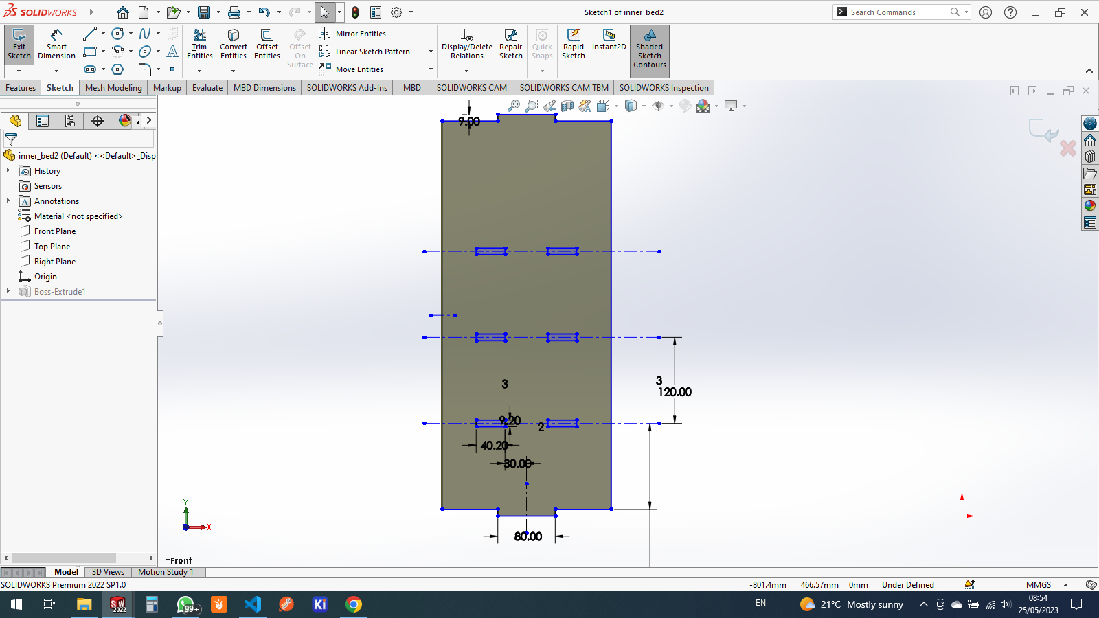
the 3d model of inside part
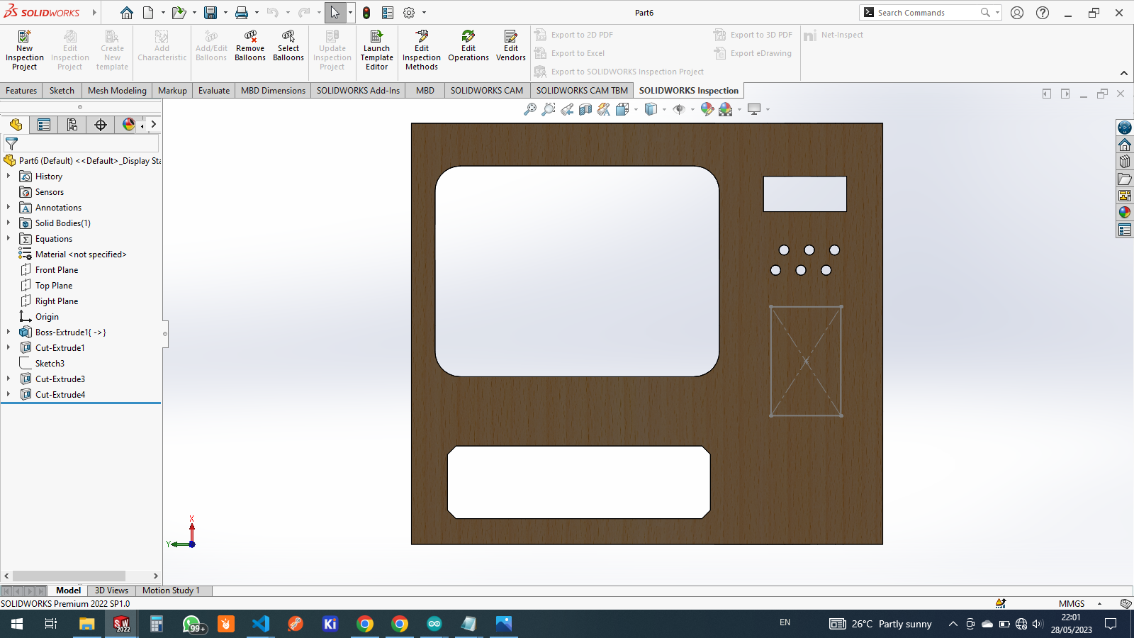
and then the front cover or as a door is designed as follows this is the starting sketch

and here is the 3d model of the front door


so from this website you can find many different components model visit www.grabcad.com
due to time availability i downloaded all models i needed from the website
the lcd display

the motors used

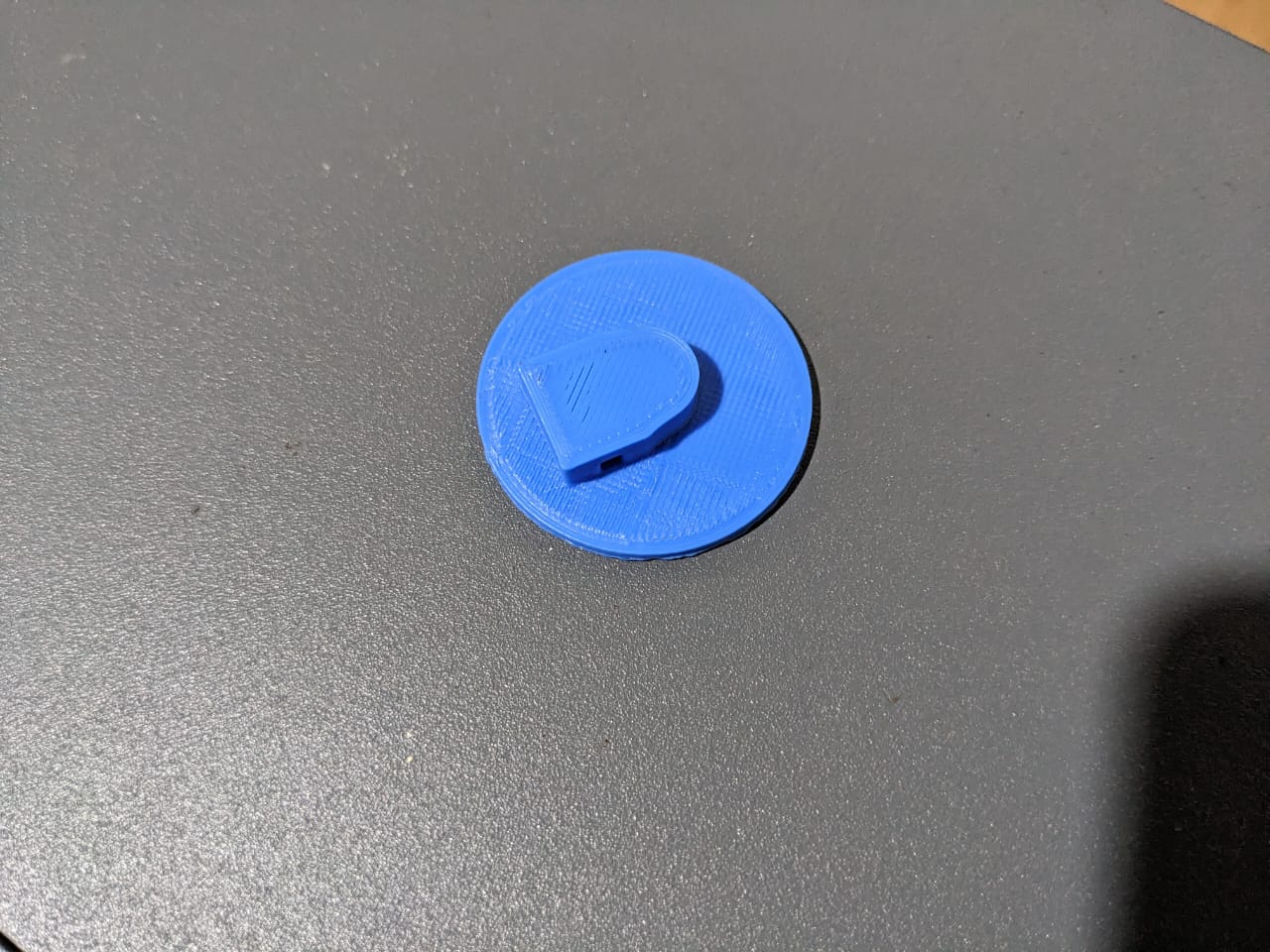
this is for holding motor shaft and a spiral structure

making spring

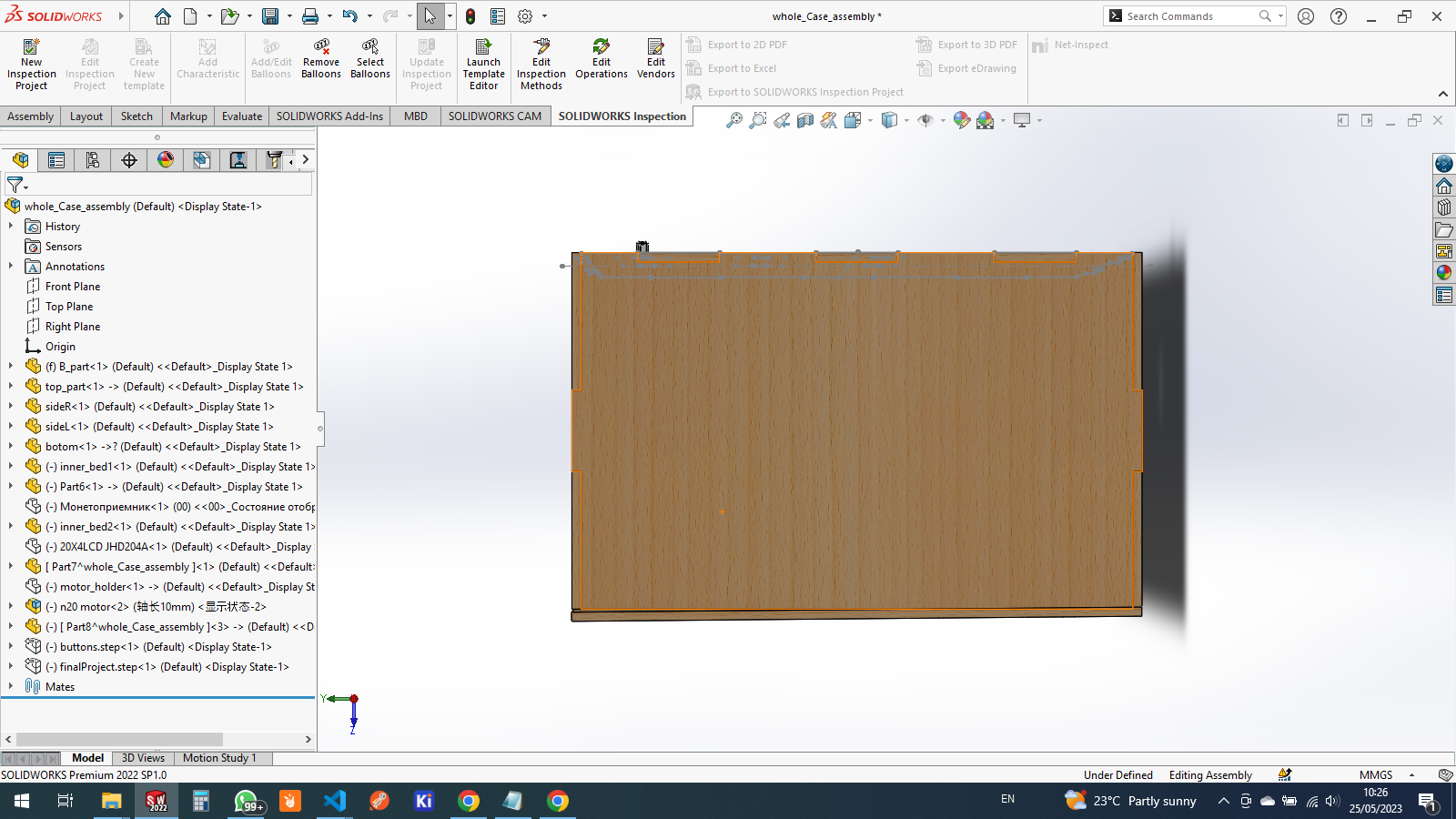
done a whole assembling
3d printing & assembly
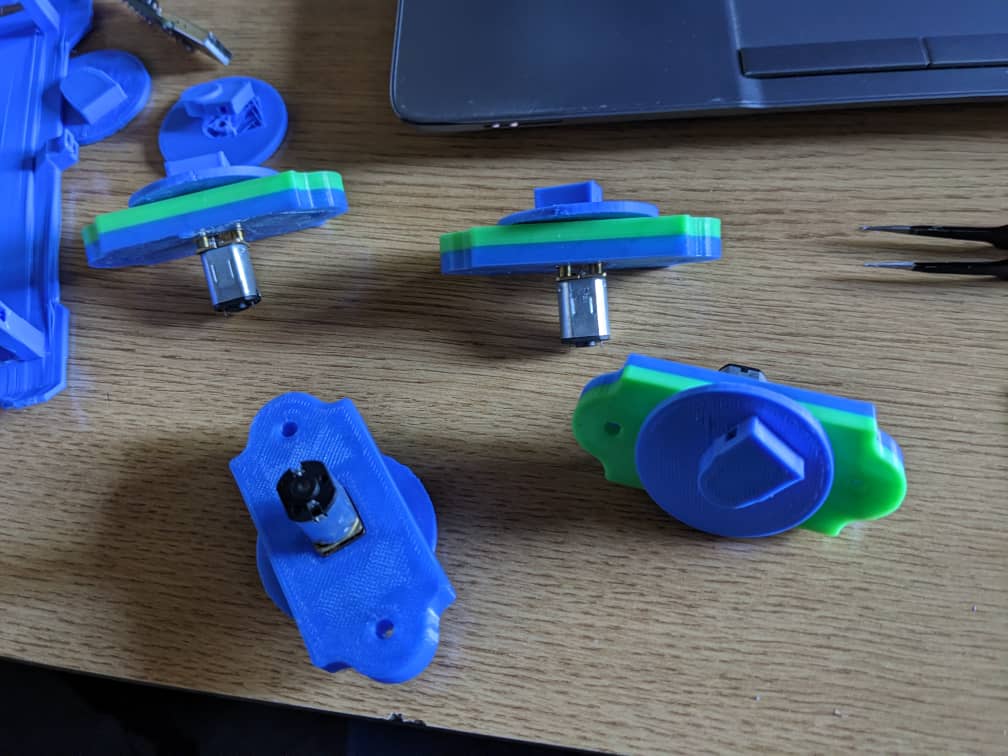
for the motor holder i have 3d printed this structure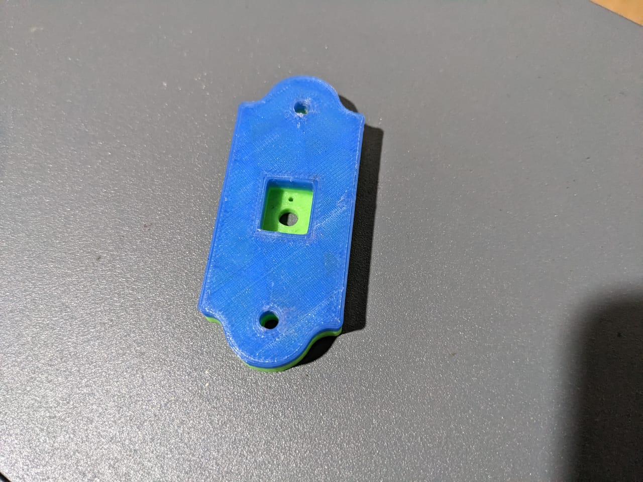
this is for motor shaft holder
assembled with motor

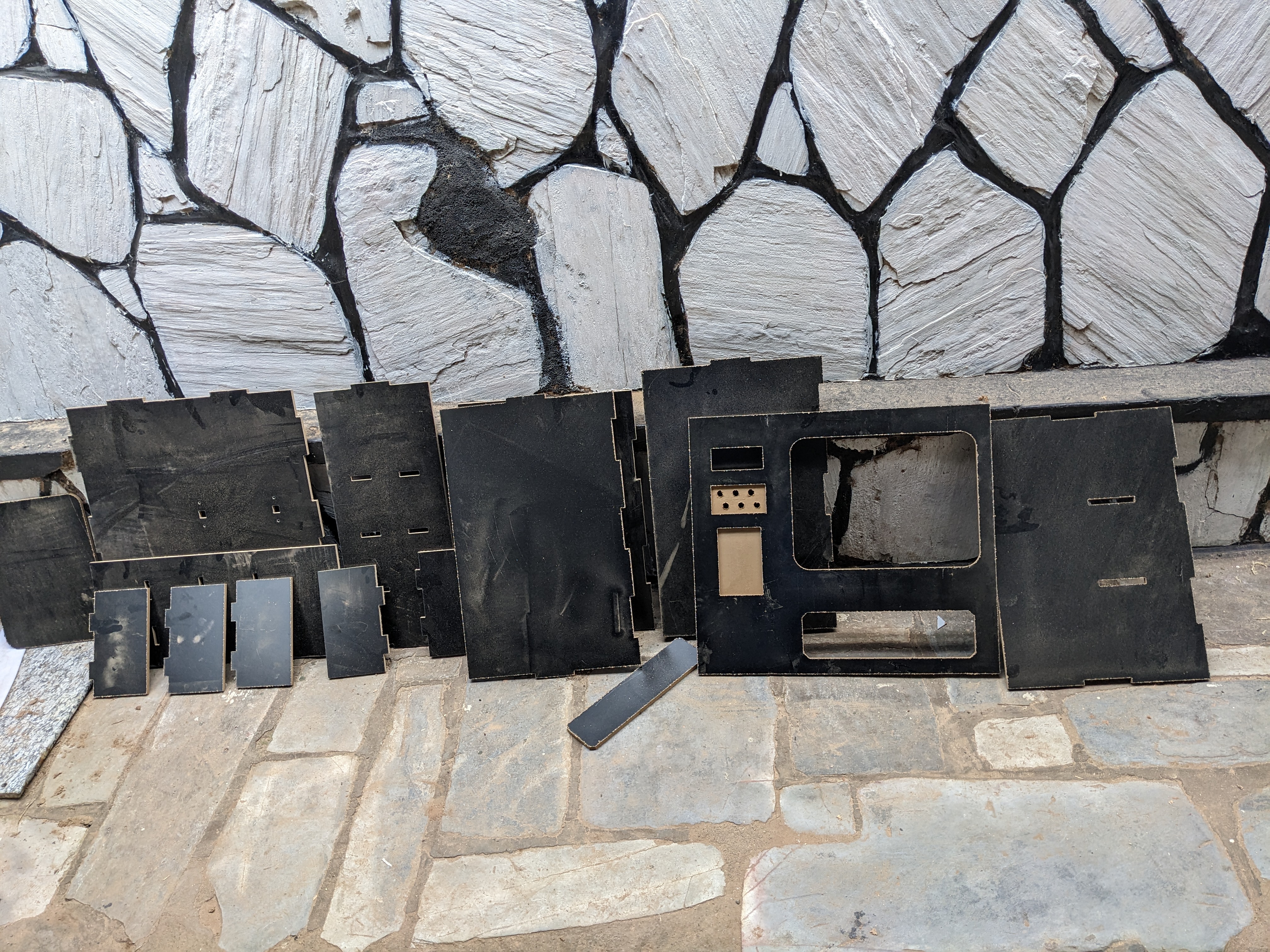
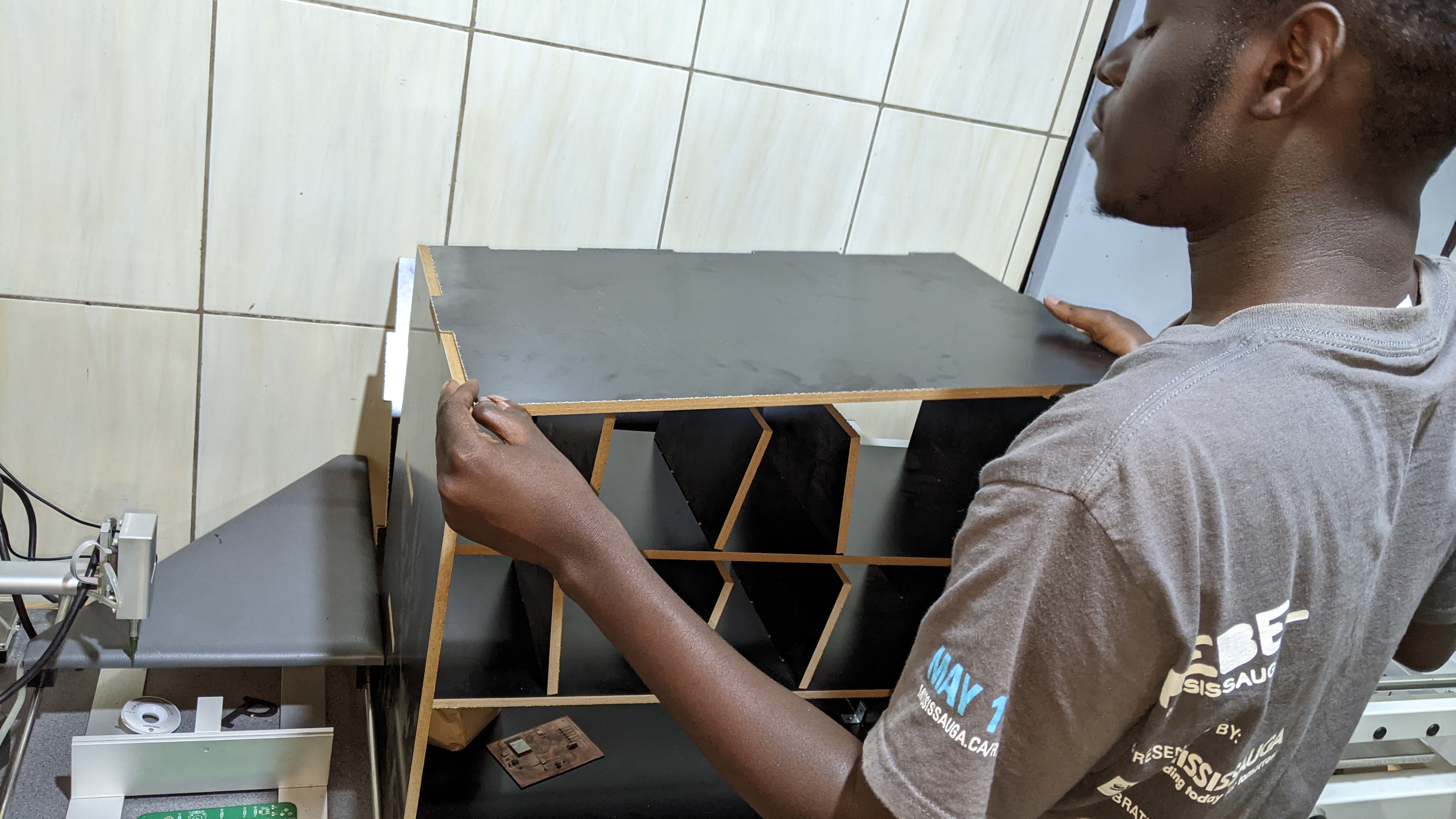
preparing for assembling 3D structure
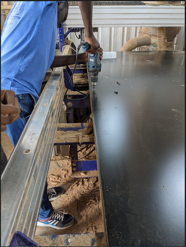

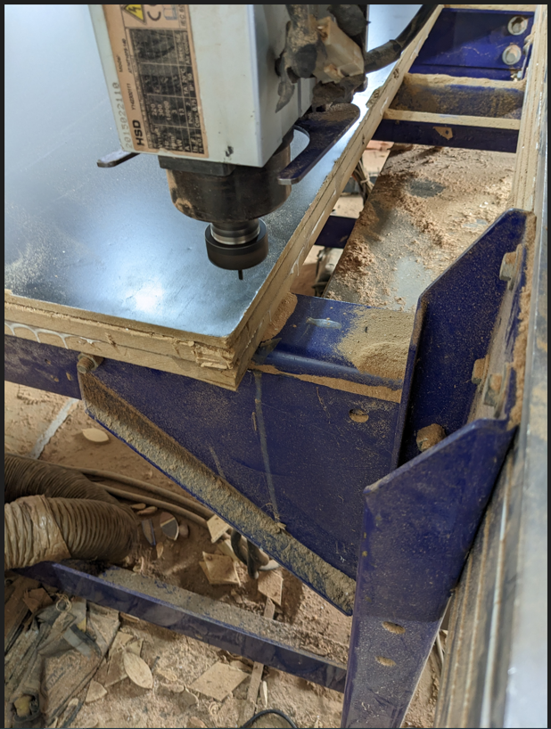
after cutting from cnc machine i gathered all parts prepared ready for assembling
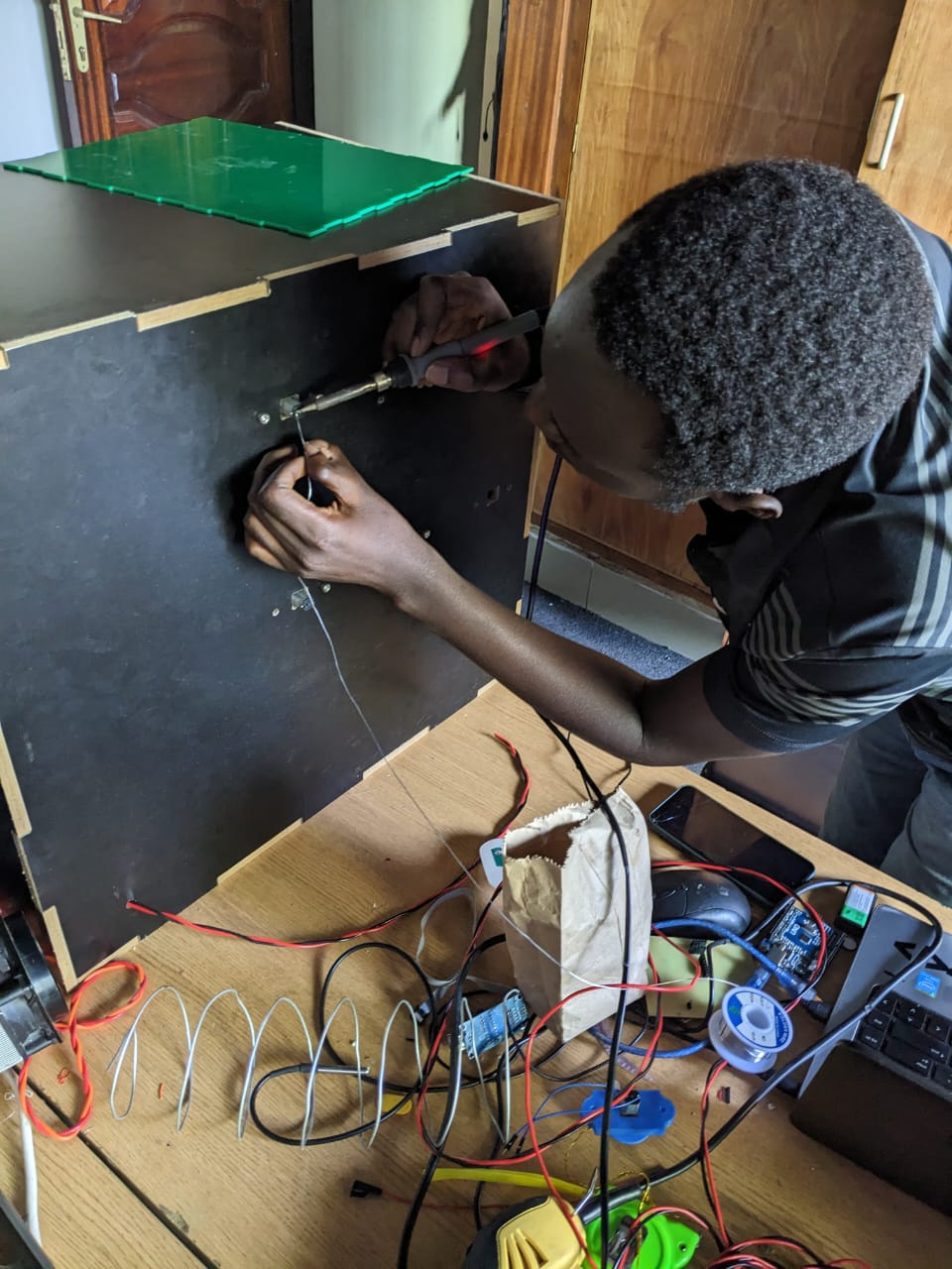
assembling the whole structure fixing all materials
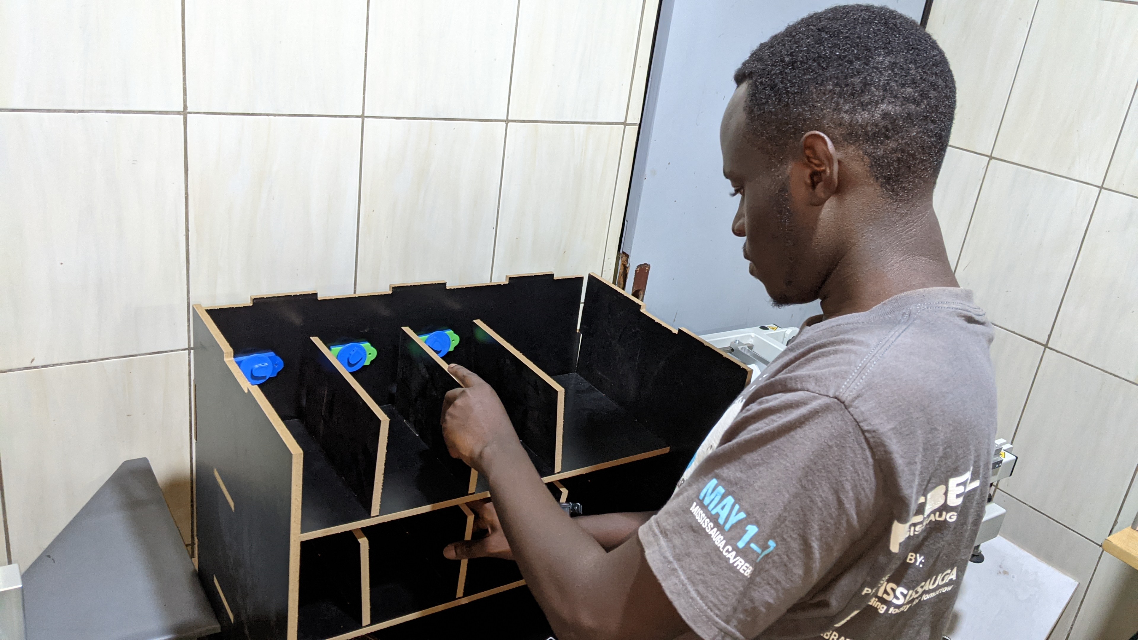
all work done then here's the final view of the project, for the logo indicating tapping card i printed it from printer on a paper
then i tapped it on
.jpg)
.jpg)
final video implementation done for the project