week assignment- computer controlled machine
Group_Assignment here https://fabacademy.org/2023/labs/rwanda/Group_Assignment/Computer_Controlled_Machining.htmlcomputer controlled machine also (CNC) computer numerical control is the automated control of machining tools
(such as drills, lathes, mills, grinders, routers and 3D printers) by means of a computer.
A CNC machine processes a piece of material (metal, plastic, wood, ceramic, or composite)
to meet specifications by following coded programmed instructions and without a manual operator
directly controlling the machining operation.
you can find more about CNC from the following link https://en.wikipedia.org/wiki/Numerical_control
CNC controlled machines
CNC machines can have several axes of movement, and these movements can be either linear or rotary. Many machines have both types.Cutout machines like lasers or waterjets generally have just two linear axes, X and Y. Milling machines usually have at least three, X, Y, and Z, and can have more rotary axes.
A five axis milling machine is one that has three linear axes and two rotary, allowing the cutter to operate in a full 180º hemisphere and sometimes more.
Five axis lasers exist as well. A robot arm might have more than five axes. for more about cnc mechanism how they works learn more from here
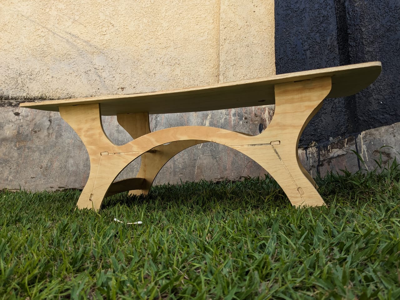
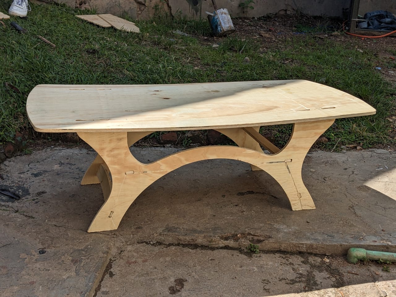
my idea was to make an artistic table that can be placed in living room or reception place or somewhere simiral
i started by opening solidworks and started sketching the main top of the table i gave it a size of about to 1m to .05m
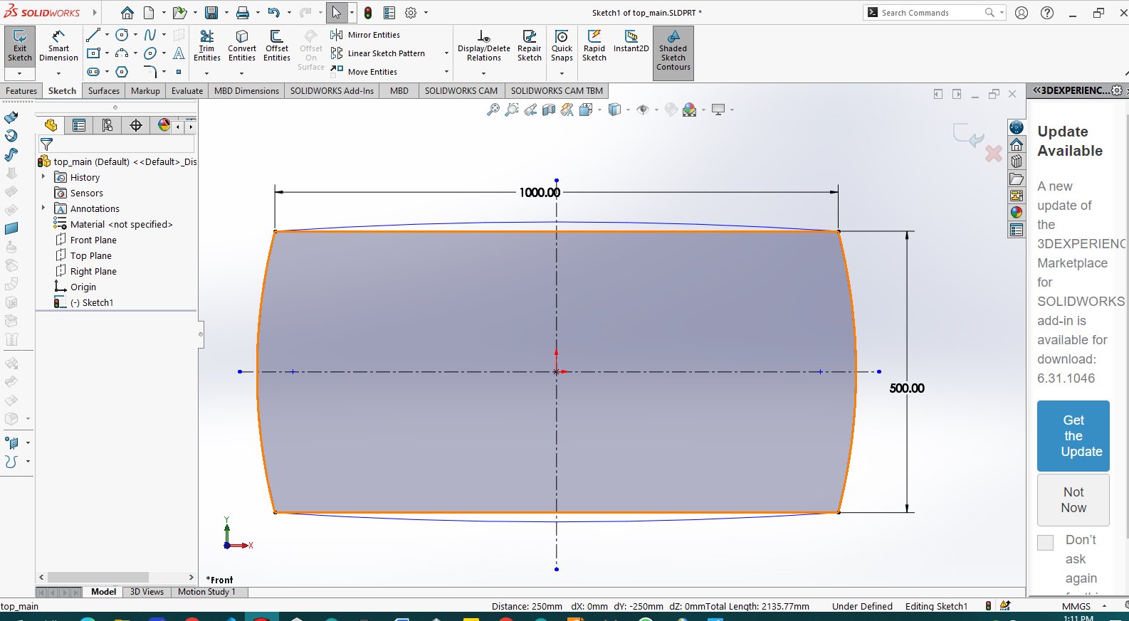
for next step i tried to make it somehow rounded on both sides and also and fillet where possible to avoid sharp edges
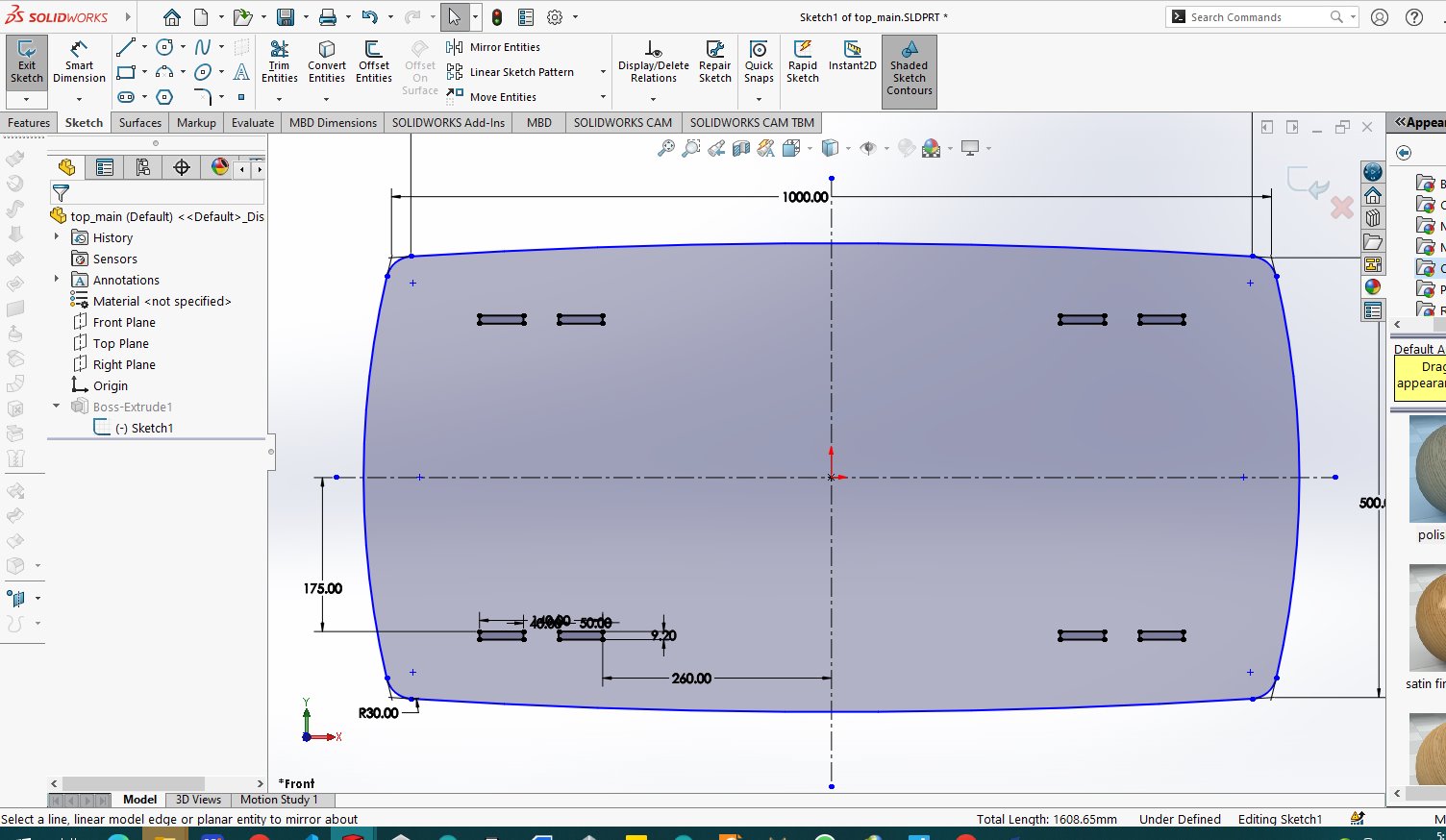
and also inserted holes to fit and conect the bottom side with the top side of the table
because the wood around the shop to be used has a thickess of 9mm so i used holes of 9.20mm for the wood to fit without

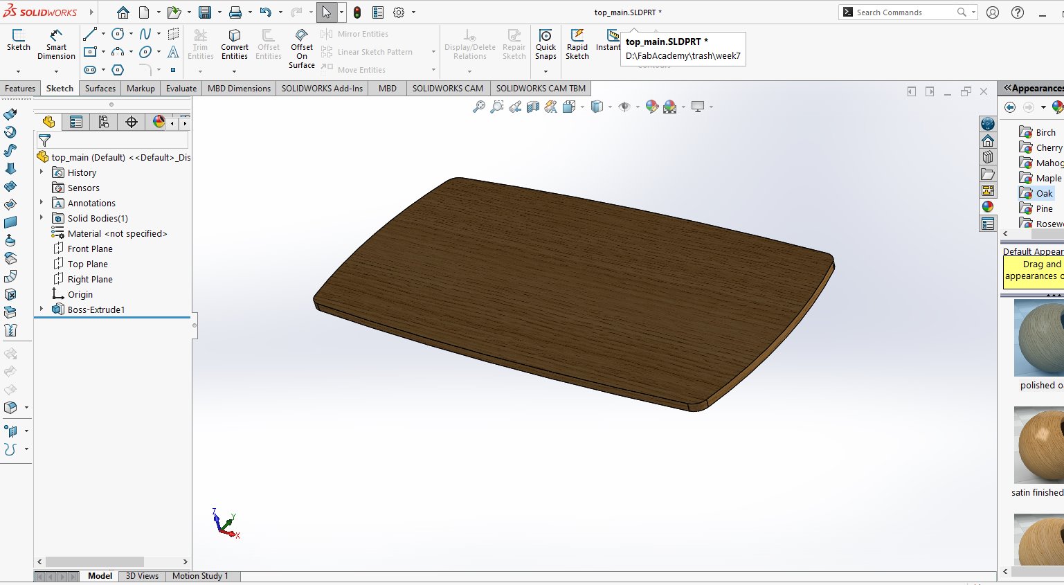
i extruded the whole object to make it look in 3d view so that it will be easy to make assembly
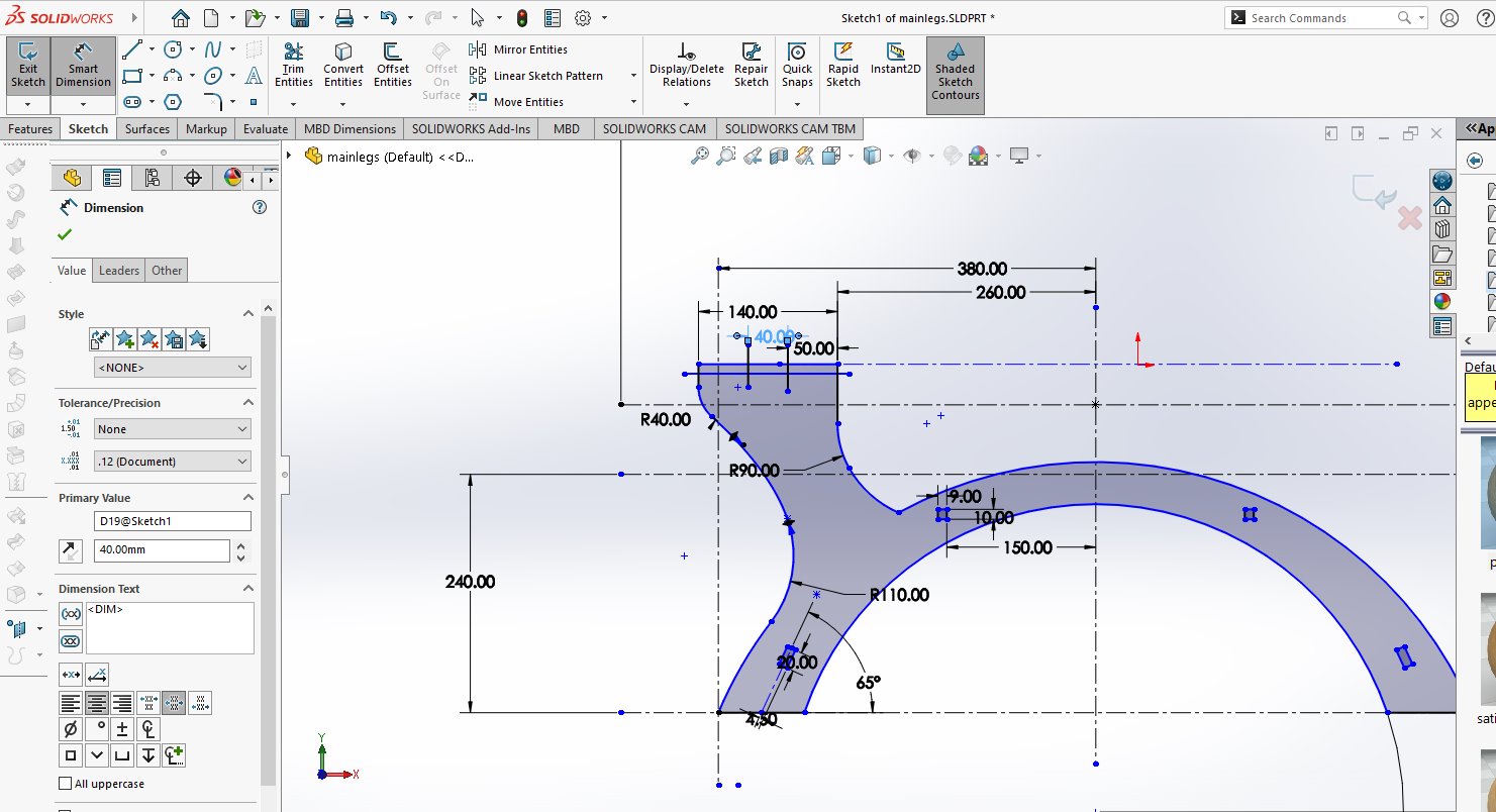
so i started measuring and figuring the how i could place legs how long in wide and length

after this study i started by making an arc with offset which both ends are the wide of the legs of the table
and also added an arm to hold the top of the table

the arm i have drawn i mirrored to the other side to make it similar and symmetric
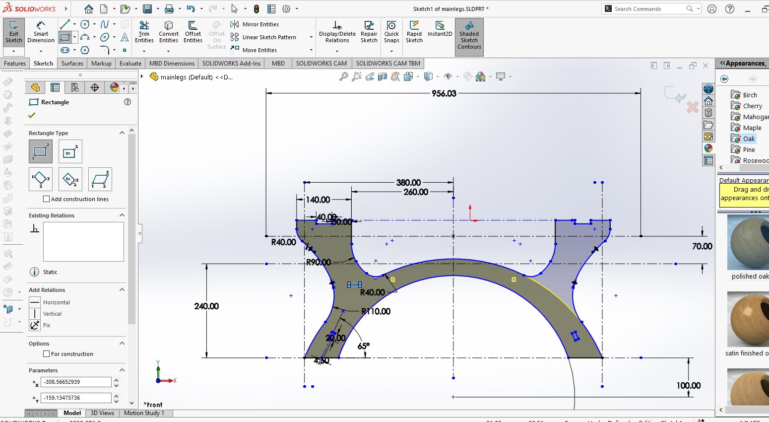
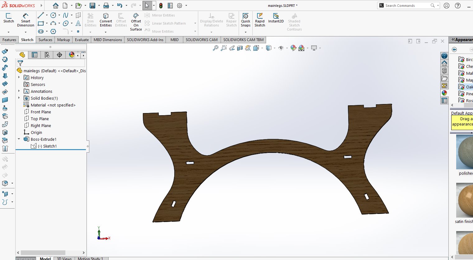
i extruded it too and changed the appearance to furniture view
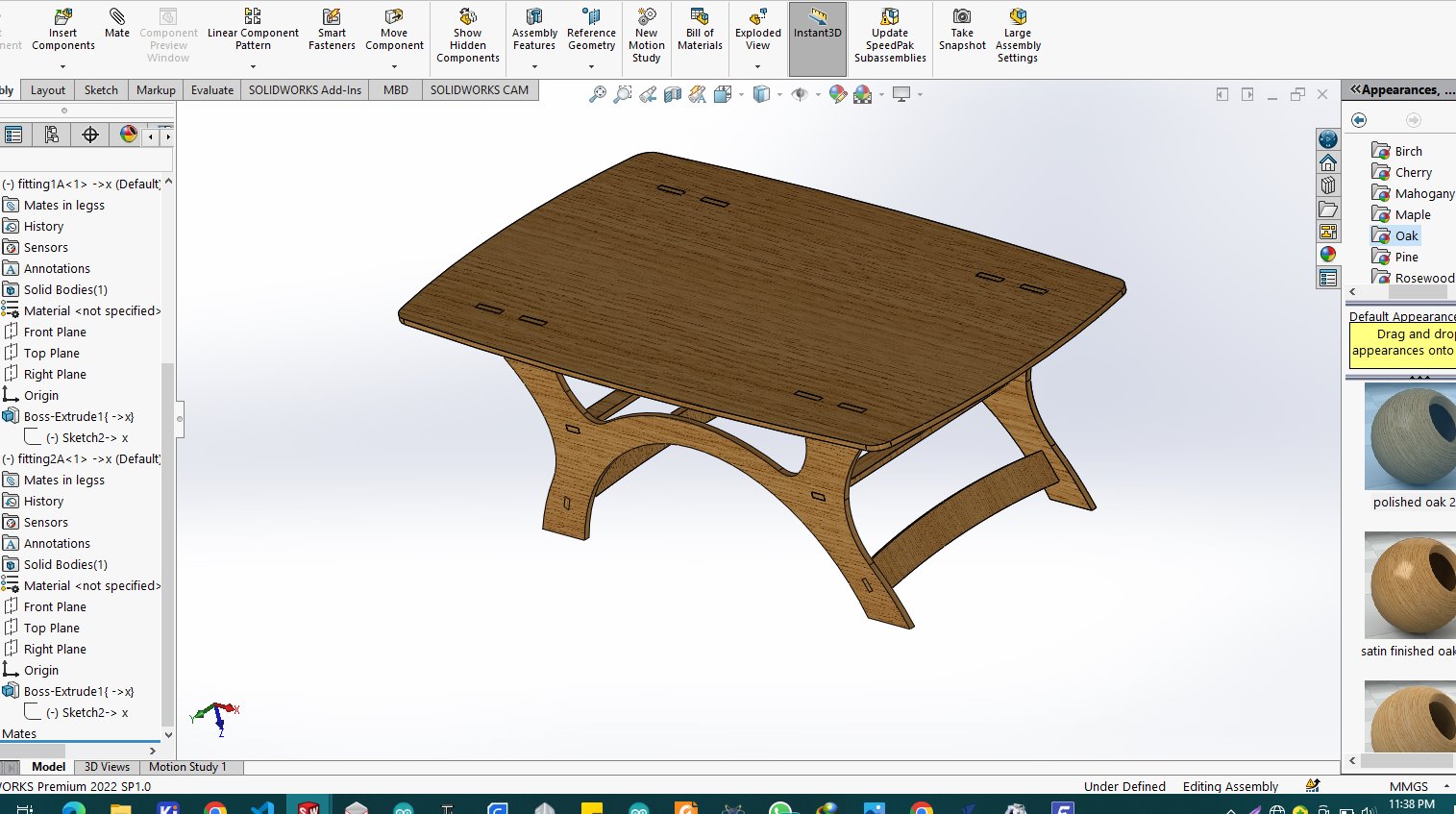
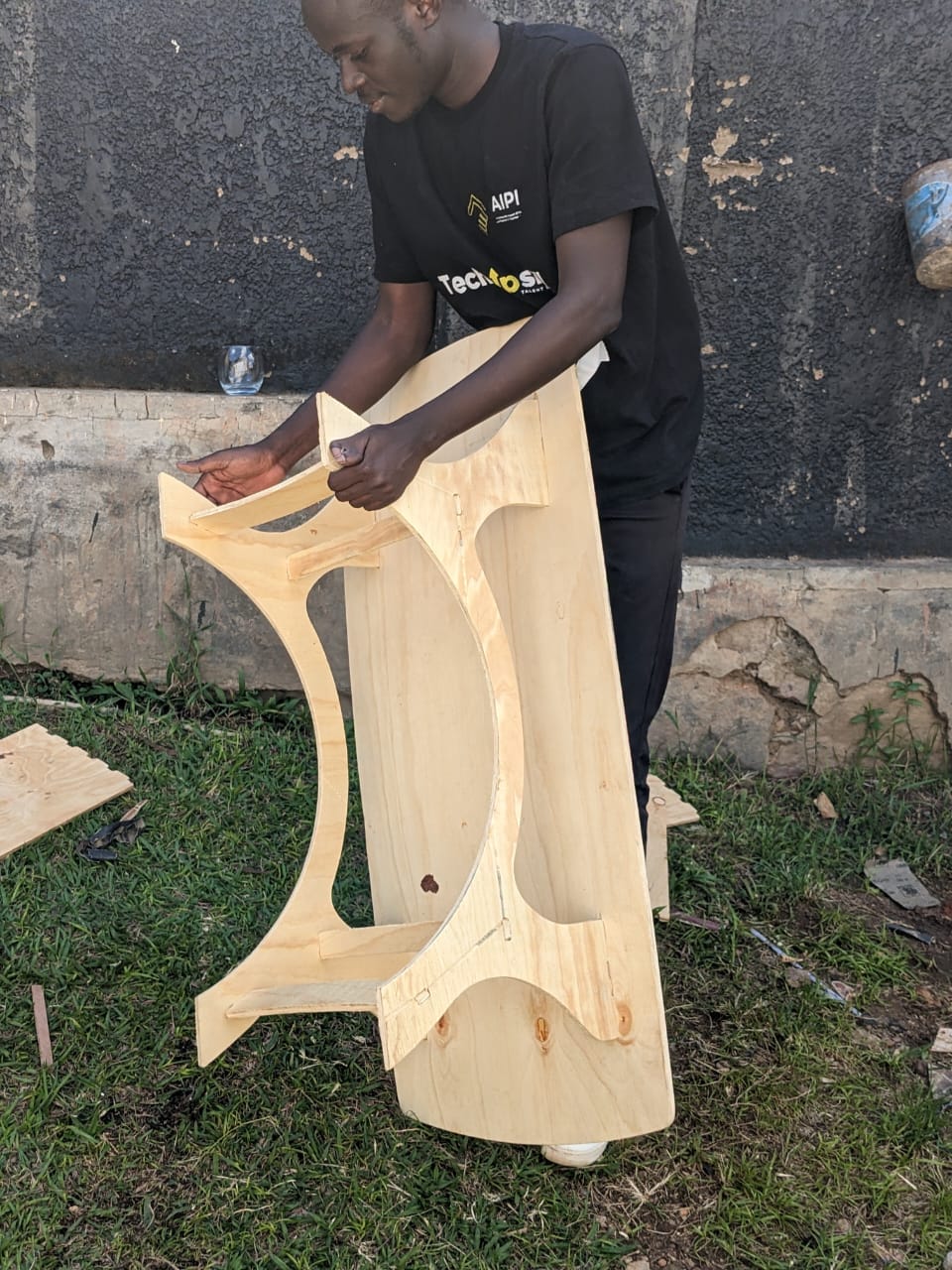
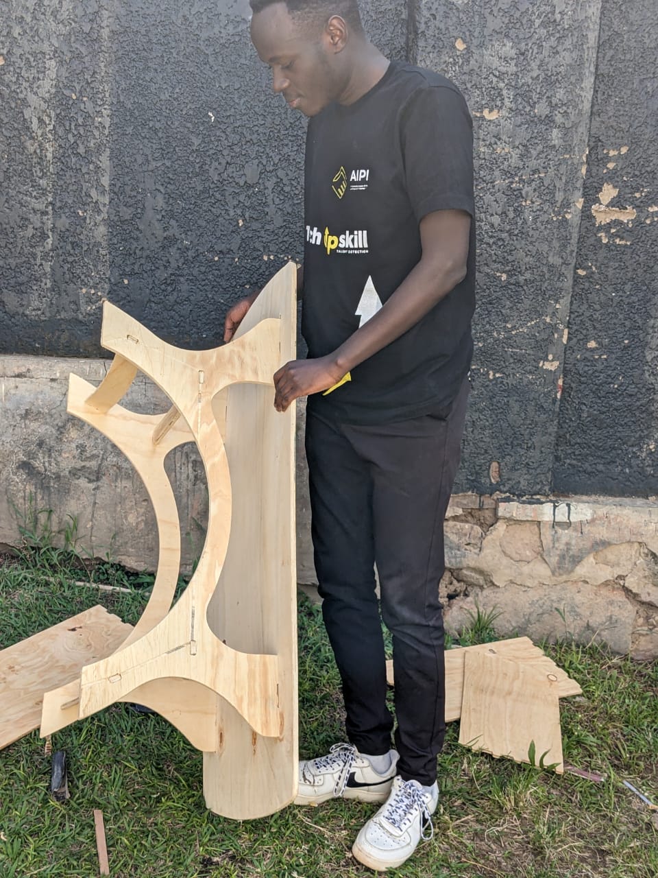
after making bottom side as legs i started the assembly where i joined the legs and the top side of the table
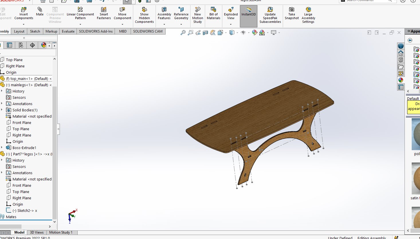
because the both sides of legs are similar i coppied the left leg side and assembled it

so within assembly i made support between legs sides
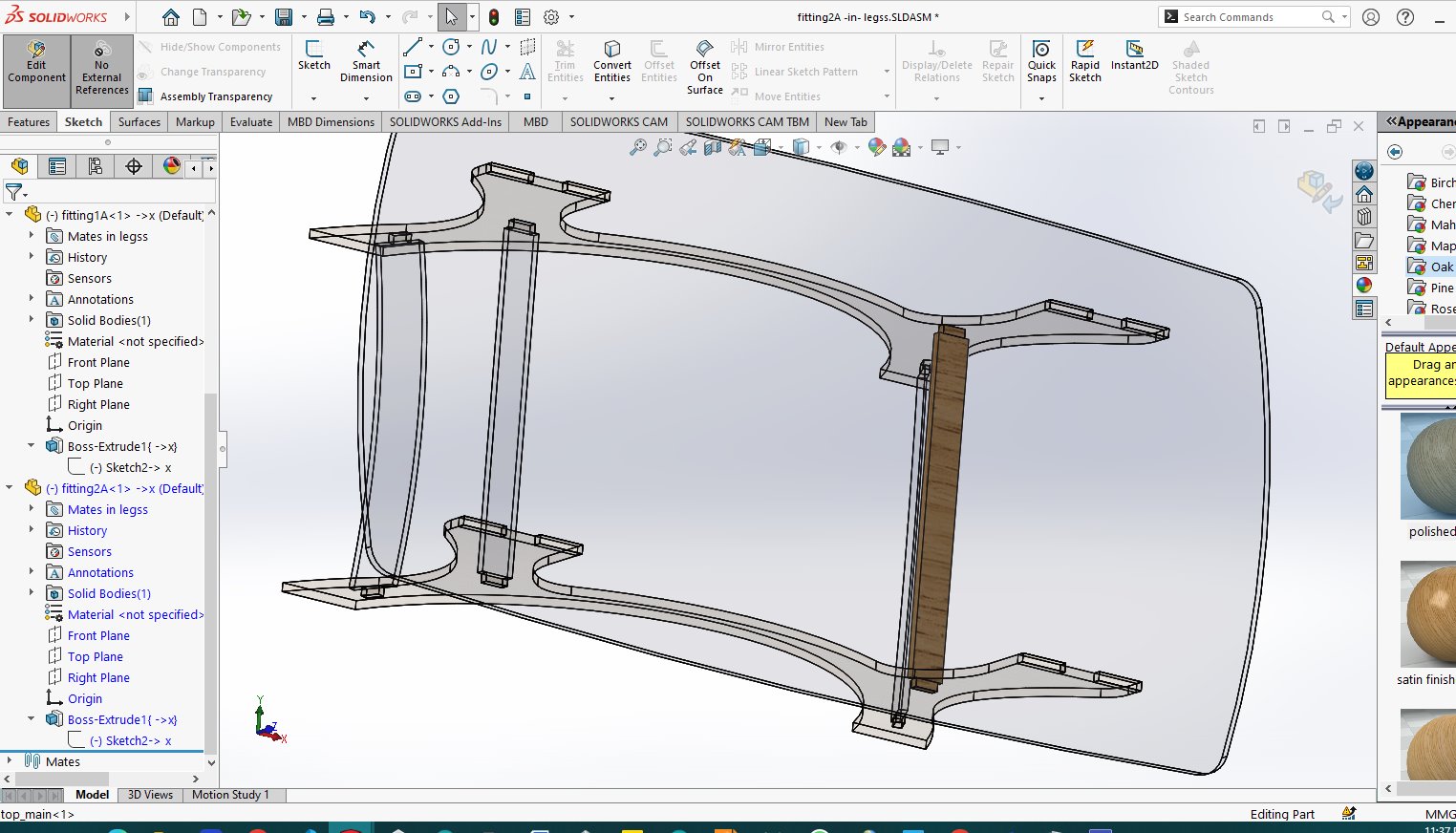
they are two different support one at the lower side and another one above
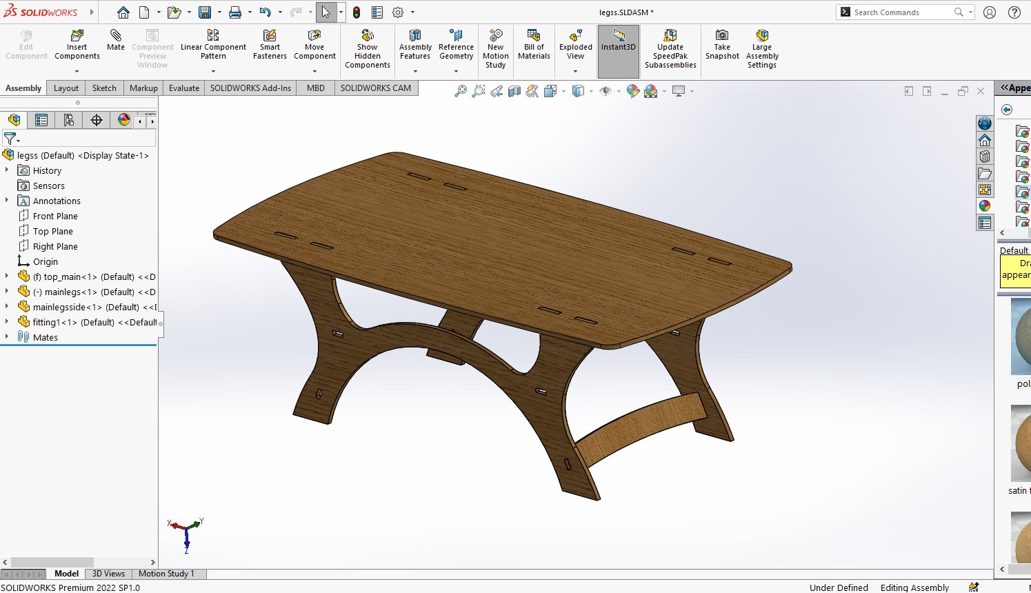
all done with assembling
when done with the whole assembly i saved the document as document
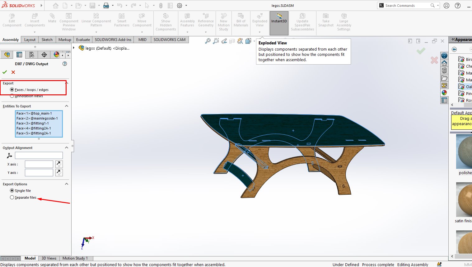
to navugate to file>>save As>> the from dropdown review i choose the DXF file
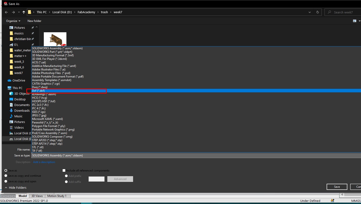
then i will be asked for output files, i chose faces and clicked to model faces which will automatically generate the 2d dxf format
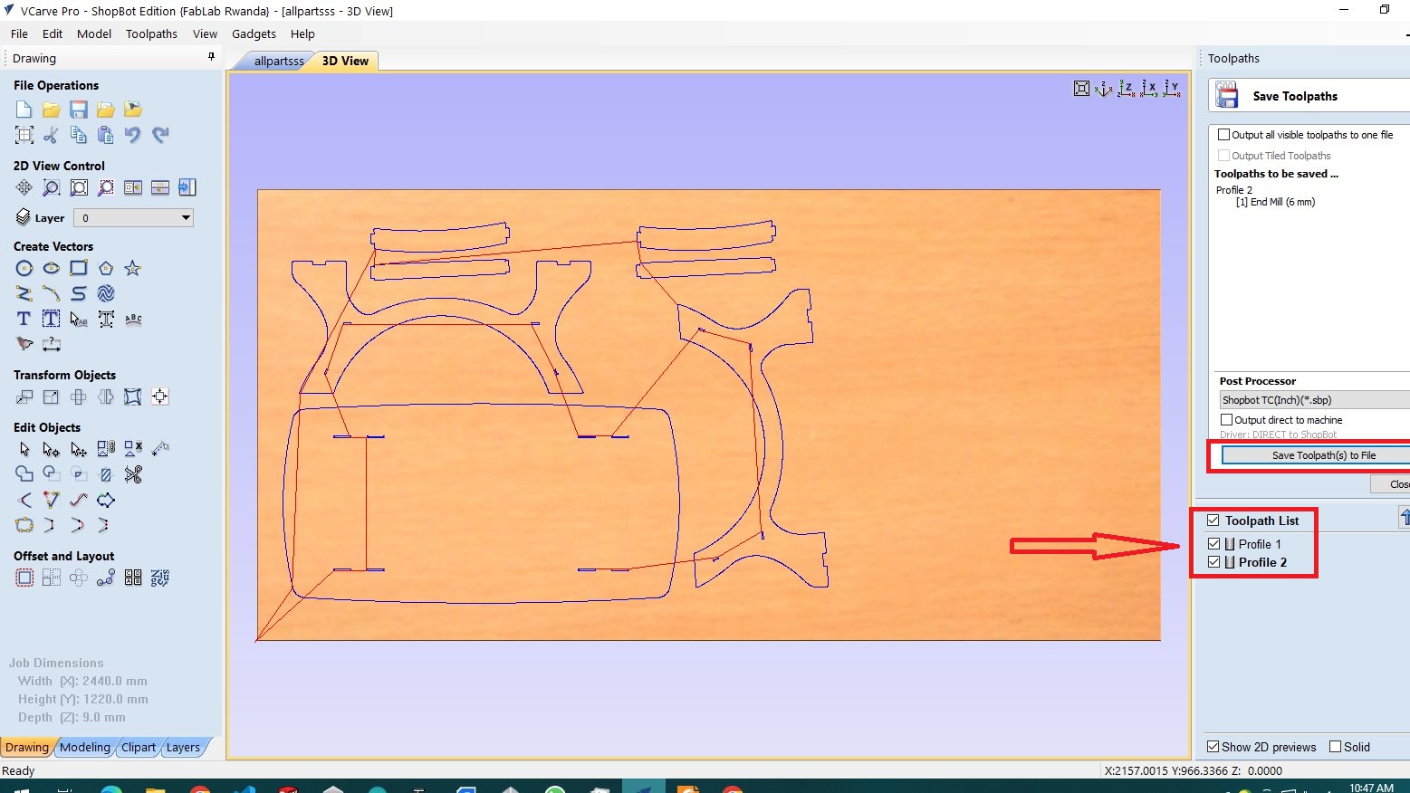
after finnishing the design i needed generate vectors for machinig so i have lanched Vcarve software that helps me to prepare the work
so when it is opened i click to "create a new file" then after new open

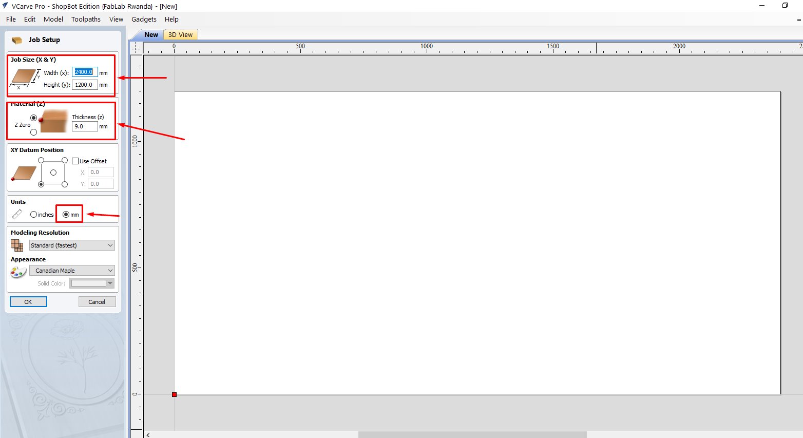
after creating new file process continues i modified the size of the sheet where i have 1200HX2400W size
and the thickess of the material all dimensions are in millimeters(mm)
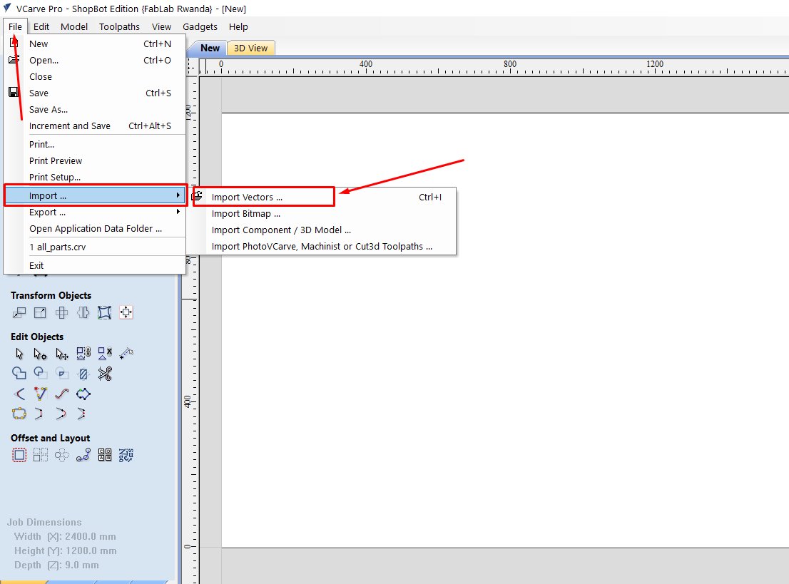
navigate to file>>import>>import vectors
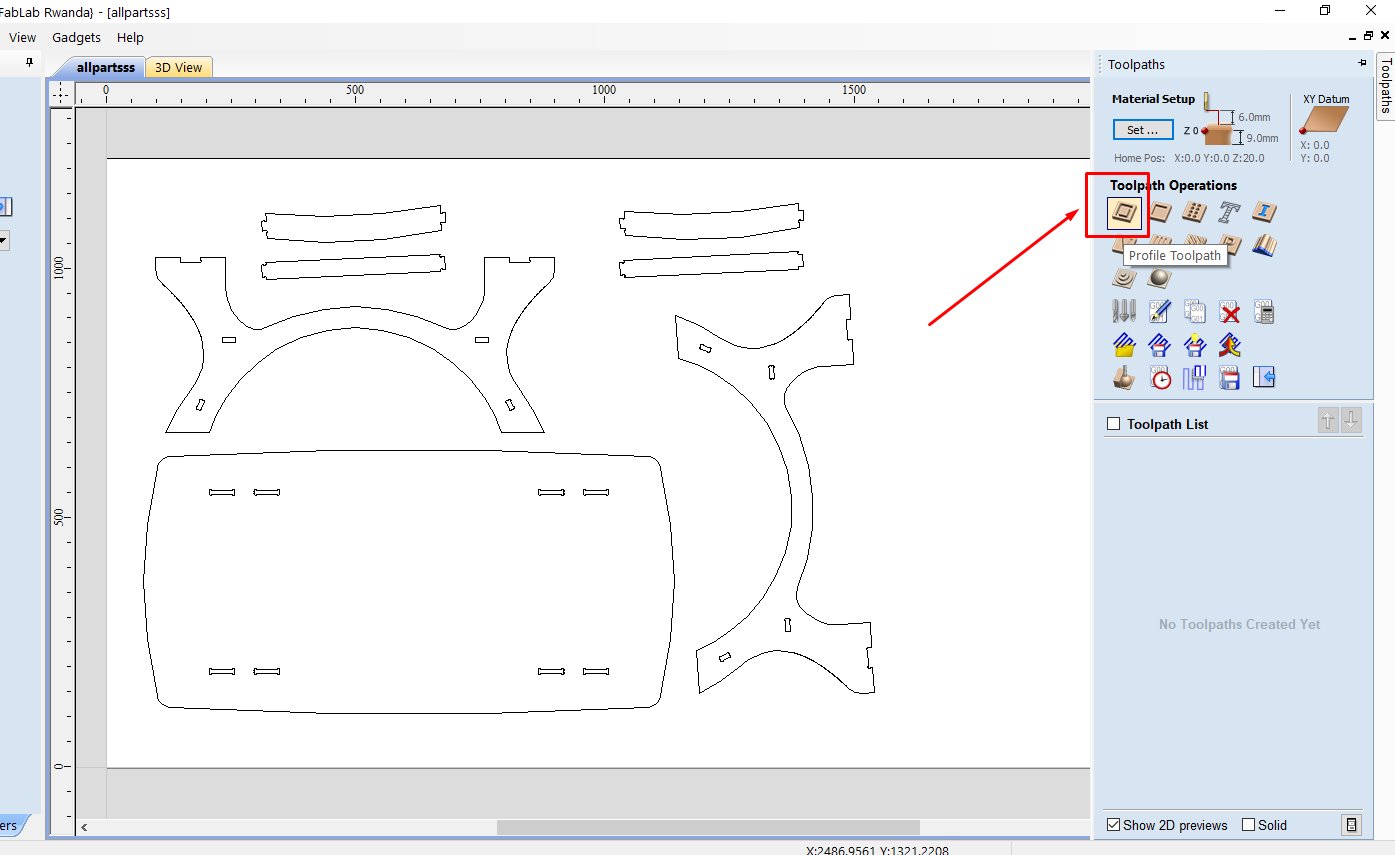
as it looks in the image i imported all parts i have designed which perfectly fitted omy wood

clicked on tool tab which is toolspath and i set profile toolpath because all parts on the sheet intended to cut through
i firstly changed the cutting tool i was using where i set the type of tool, diameter, spindle speed, feedrate
so these parameters are determined by the type of material we are going to use

next i selected machine vectors they are three types of them that we have, "outside, inside, on"
outside means that the tool will cut through outside on edge line, and vise versa inside the the tool passes in front of the edge line
but inside, on means that the tool tries to cut throuh line in the middle
these inside squares meant to fit with other cutted materials we cut a hole without changing the dimensions of the square hole
i selectrd inside profile
selecting cutting
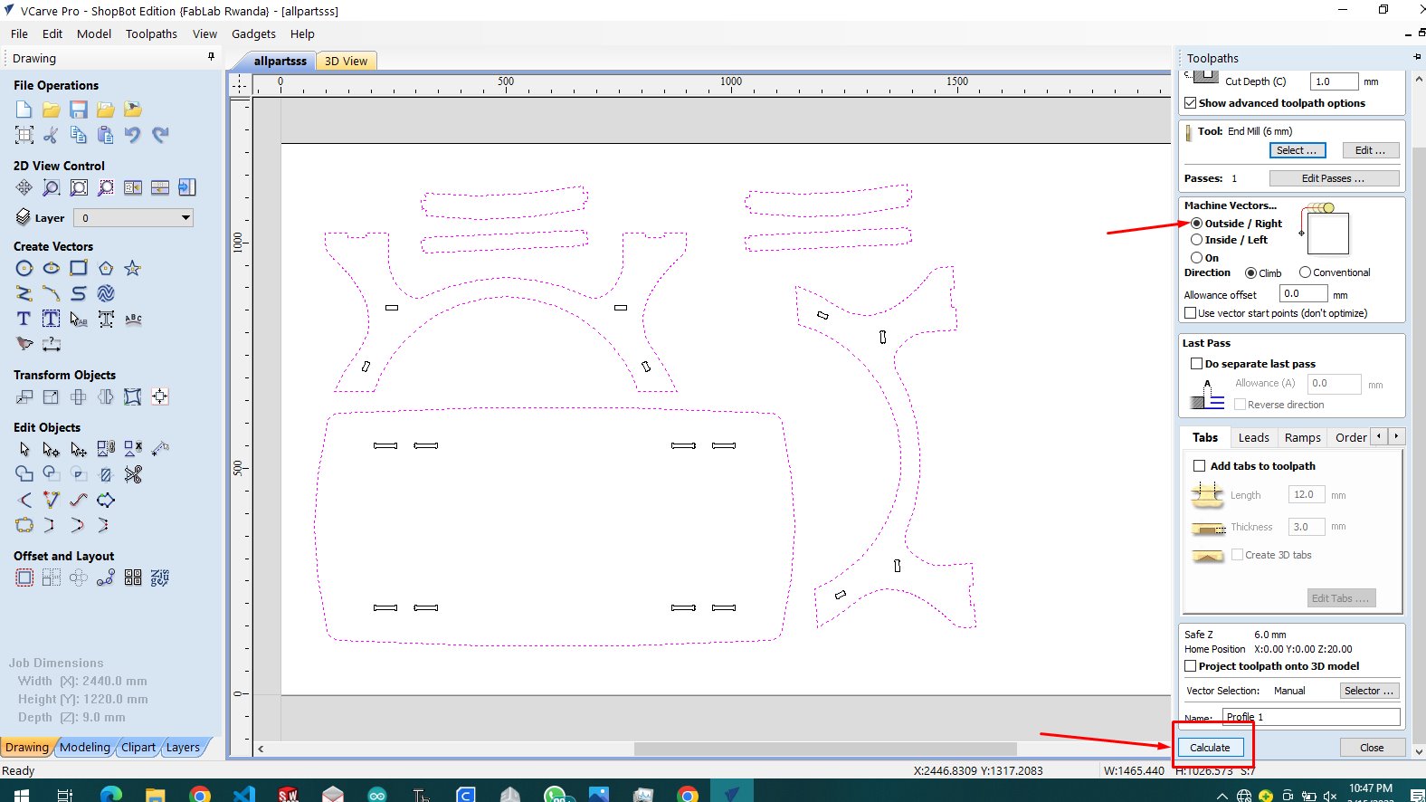
when we are done configuring we click on calculate, and it shows simulation model and tool path movement
click on shown icon to save the toolpath and material so that you can use it later on
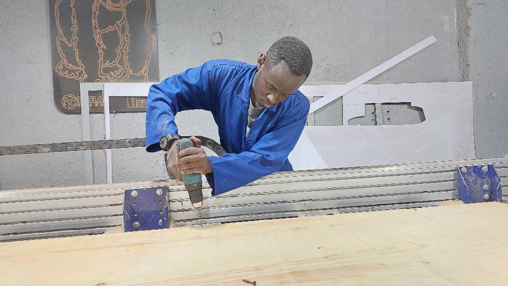
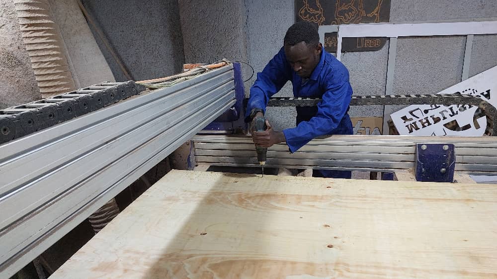
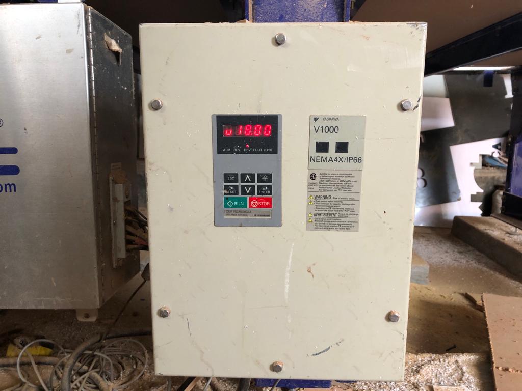
so after dealing with software i headed to real work i started placing plywood sheet on CNC bed and inserted screws to fix it and stays stable
i opened shopbot software controller to set all axis desired orgin as 0, we click the navigation buttons or similar to keyboard
then i click to zero axes button and i select axis to 0
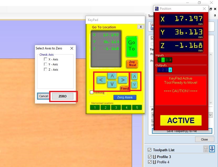
so i clicked to cut then i choose the saved profile
for our CNC it is set to 18RPM by default spindle speed


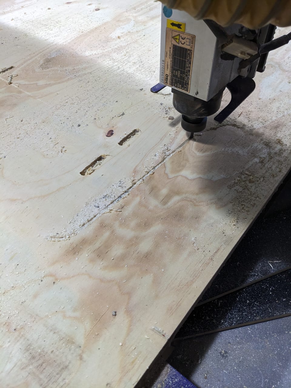
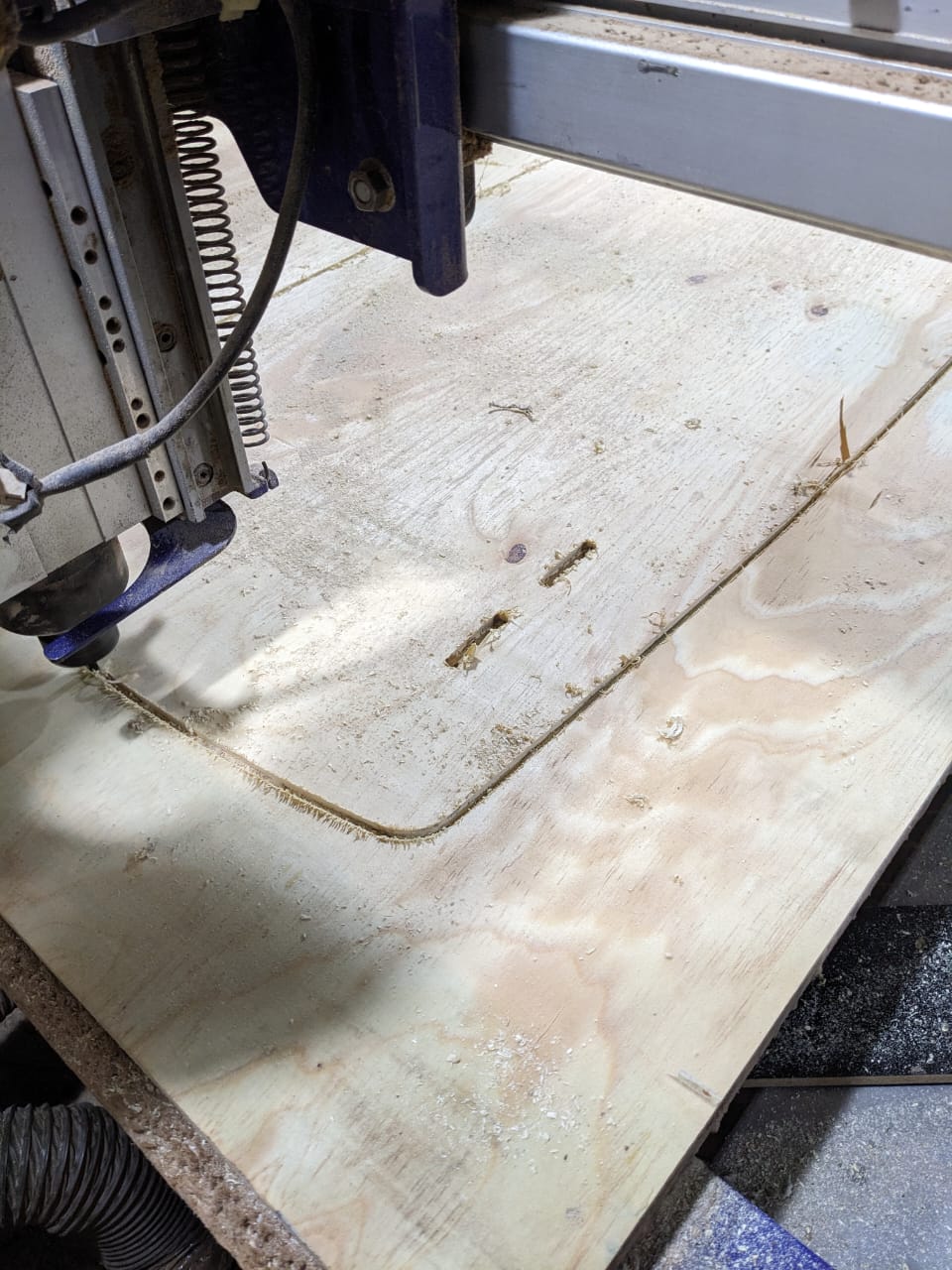
after cnc is done with cutting i move all cutted parts from bed
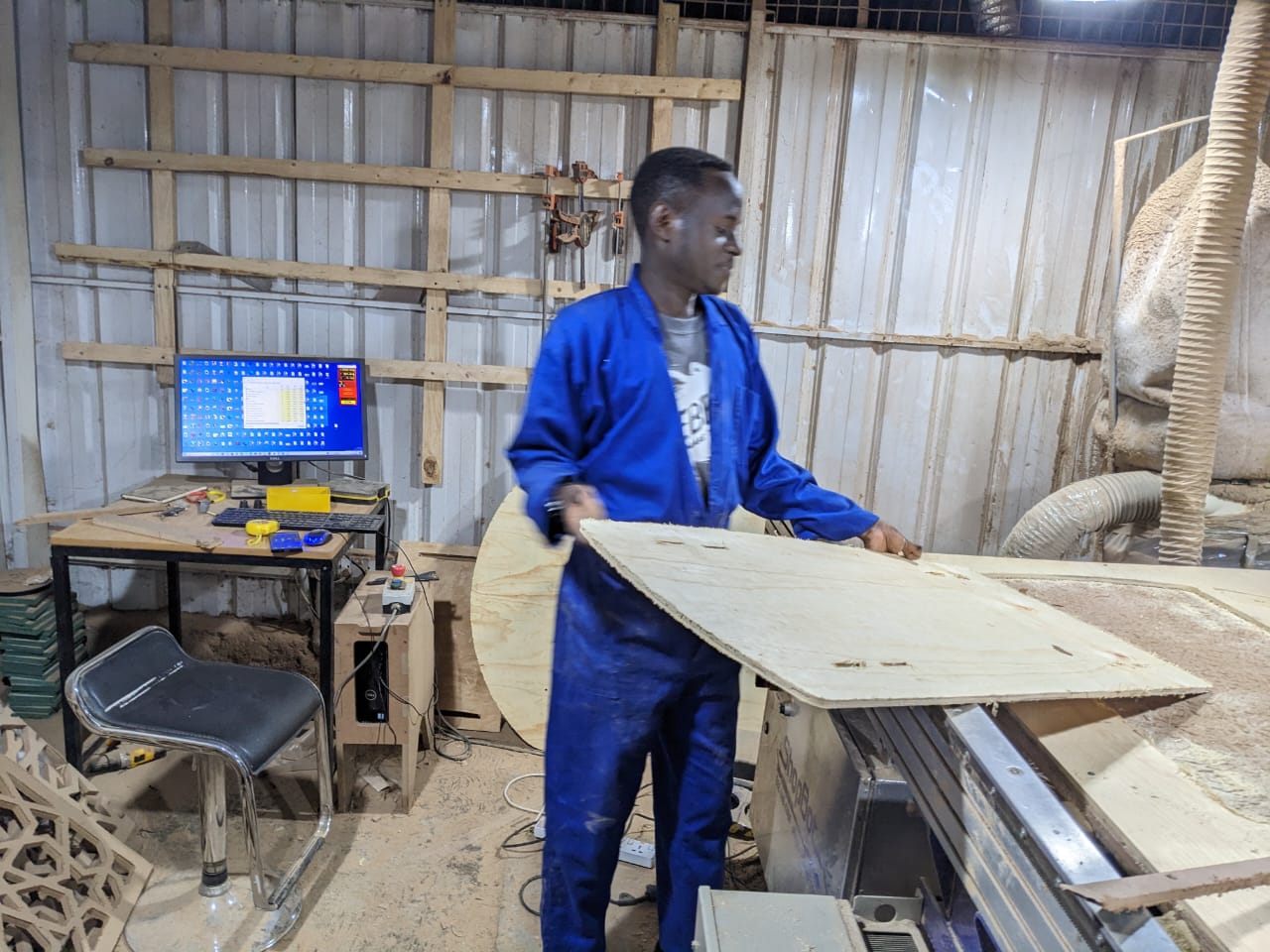
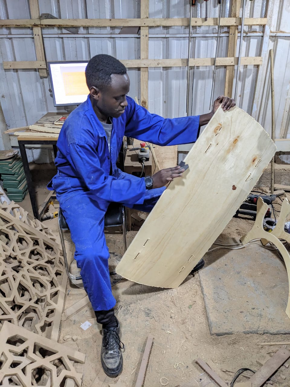
by the excess of the material made with cnc i took the sandpaper and sanded the materia to make it better
as it is viewed in modeling software, while i was preparing for assembling the all parts


after sanding and preparing the materials i started assembling on next day
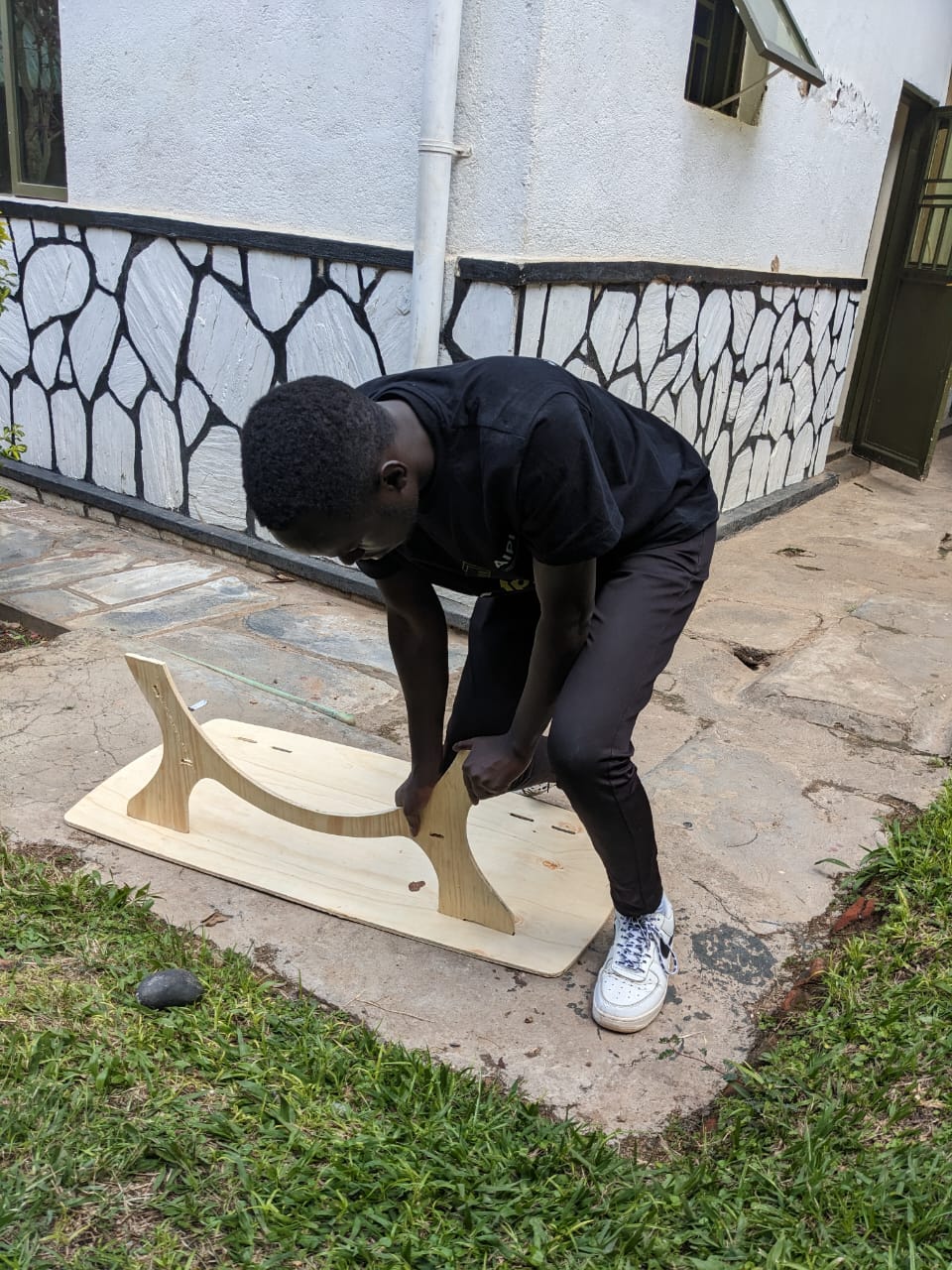

the problem i have occured from this proces of making my table the joints clearance was a bit small
so i have used sandpaper to remove a little amount of wood to change a clearence so they fit
click download button below to download all CAD files i have used