- power
- laser light generator(laser tube)
- mirrors
- motors and frame when a light is generated from laser light generator(laser tube) it points to the mirror and reflects beam to the lens as shows image demostration
- CO2 laser usually this type of laser is used to engrave or cut through non-metalic materials like wood, plastic, glass, fabric, and so...
- fiber laser this type of laser "fiber" is also used to cut and engrave through metalic materials.
- engraving
- marking
- cutting our lab laser cutter
COMPUTER-CONTROLLED-CUTTING
assignment focus on making a parametric press fit construction kit, and cutting on vinly cutter
the assignment above is individual and for the group assignment refer to the link https://fabacademy.org/2023/labs/rwanda/Group_Assignment/computer_controled_cutting.htmlwhat is parametric design Parametric design is a design method where features (such as building elements and engineering components) are shaped
according to algorithmic processes, in contrast to being designed directly more about click here
computer controlled cutting, is the technology that uses a laser to cut or engrave material based on computer controlled parameters.
with the help of highly power generated tools, this computer controlled cutting machine can cut through different materials like wood, plastic, glass, metal, fabric.
in our lab we have covered about laser, how they works how the structure how they are made and working behavior behind them.
how laser works
laser cutter structure is composed with
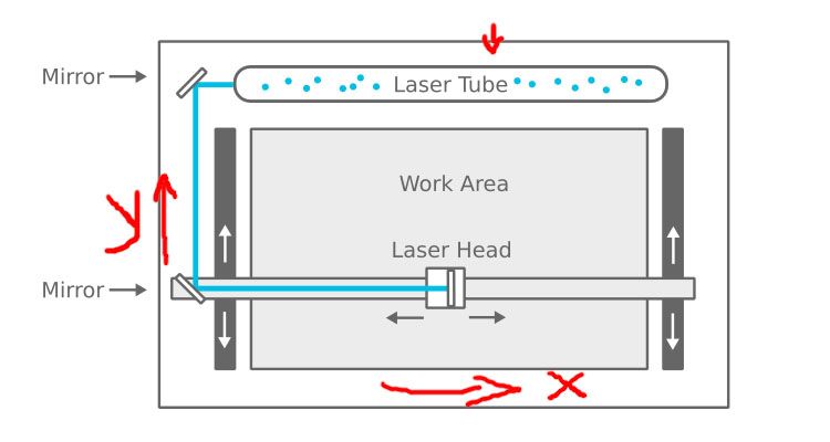
the X and Y axis movement are moved by motors used to roll the movement of the laser cutting depending on design from computer and command
laser stands for "light amplification by stimulated emission of radiation"
main types of laser
CO2 laser has wavelength between 9.3 - 10nm
fiber laser has the wavelength between 780 - 2200nm
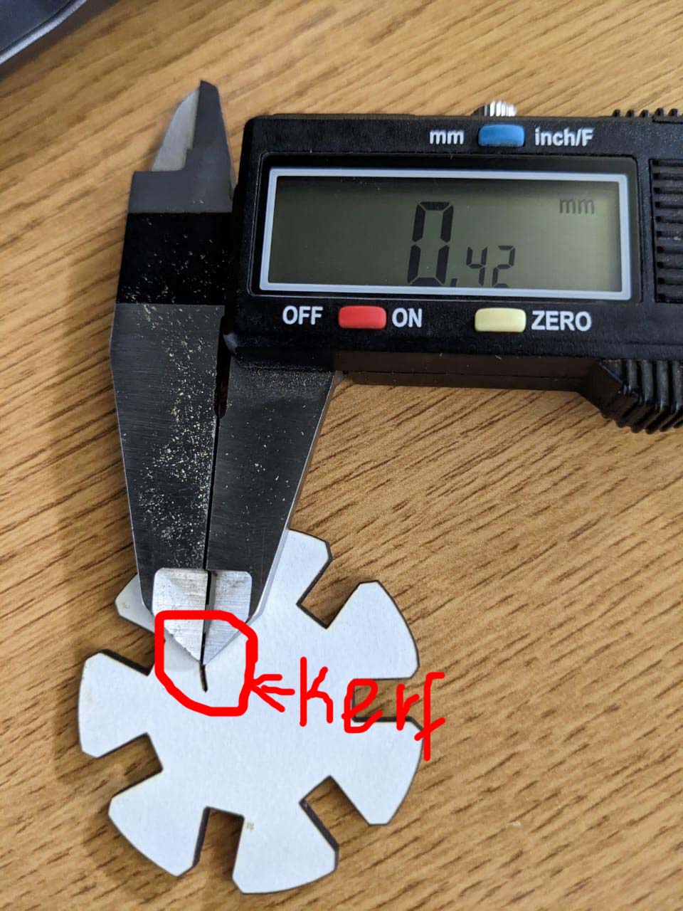
laser kerf kerf is the ammount of size line between 2 cutted objects this type of size is determined by laser size
laser terminology
in our laber we have epilog laser cutter visit their article HERE

there's some parameters we needed to imprement assigned assignment
kerf and thickness
as an assignment mentions me make press fit, that has to be fitted against each other to make it fit well we care about "kerf" parameter
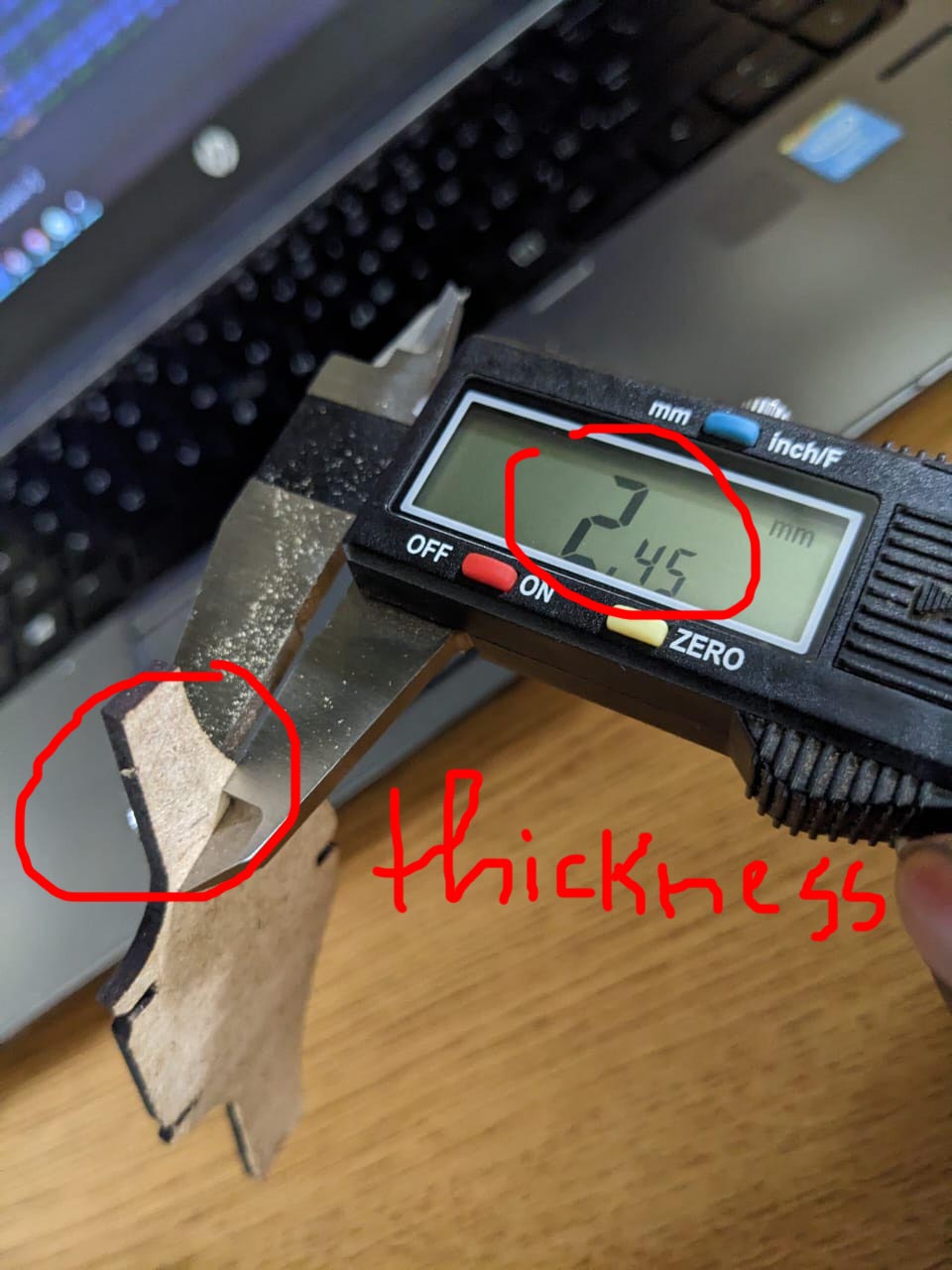
for our case viny cutter we use has a kerf of 0.42mm and our material thickness is 2.45mm
as you see in image i have used caliper to measure the thickness of the material and the thickness of kerf.
there's an issue when i designed an object without considering kerf, and here's what can happen, the materials are loose.

after collecting all those informations and fixing issues i started designing in solidworks designer
making press fit
after learning about laser cutting and also about computer aided design i was able to design a kit and make it through laser cutter.firstly i openned solidworks designer where i have designed the kit, i chose solidworks because since i was using it at the same time with freecad
solidworks is easily to use and has more accesible features than others, so in order to make it quick i opened solidworks and made new sketch design
as the assignment mentions i made "parametric" sketch design to make this press fit to make grobal valuable in dimensioning type"=name" then okay for the other similar object we call this valuable.
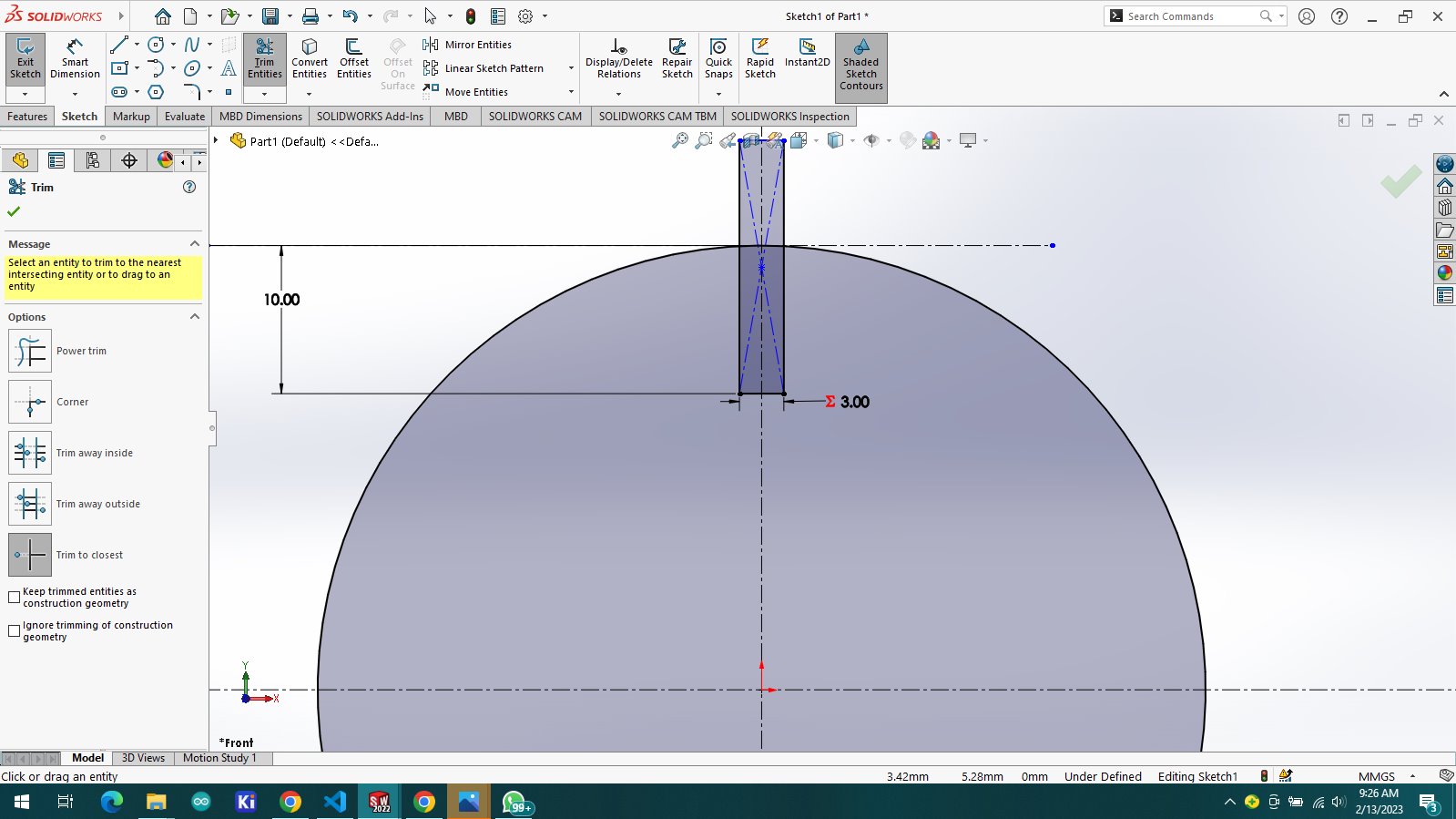
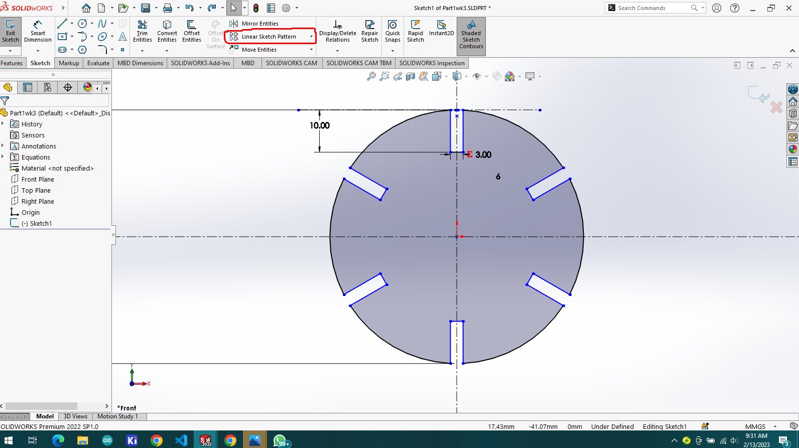
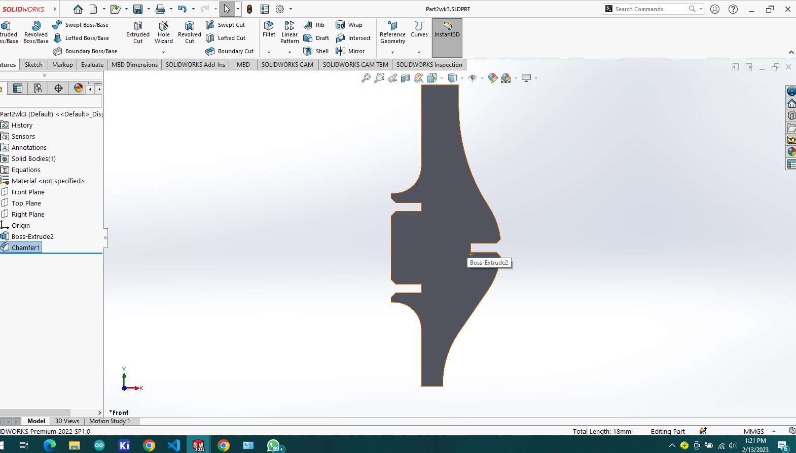
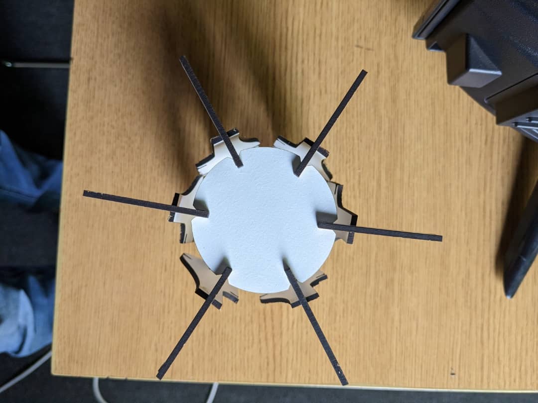
the first object that i made is circular having 6 cutting slot on the end of it each slot has spacing length of 2.45mm but our laser has kerf of 0.42mm, the method is to open in sketch mode and select the
the sketch has the form of rectangle and then i selected linear pattern with 6 duplicates
after this sketch i made circular pattern to make all six slots around
notice that all the dimensions made are globaly, means what, if a dimension is set as global i can change one value and
any other value related to this value will also change accordingly, so by using linear sketch patter i multiplied the rectangle slot into six
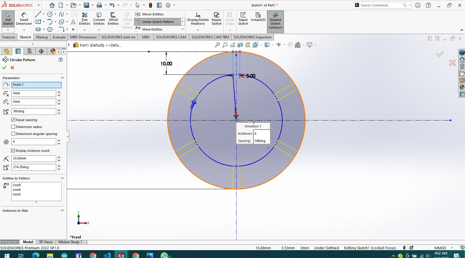
resulting this after circular pattern and made an extrusion to make it in 3d view

Parametric mean
so in assignment it is mentioned that the design should be parametric, so i have design in a parametric wayas it is shown in the image below i set a grobal variable to some dimensions o that if i change one parameter i changes all
related dimensions i dont have to go through all dimensions and change individualy so with my design
here shows how it is done in the image below how i change one parameter and all dimensions changes
above design work tree on equations right click on it and choose equation management
and as it is shown the cutted slot has length of 5mm width of 2mm
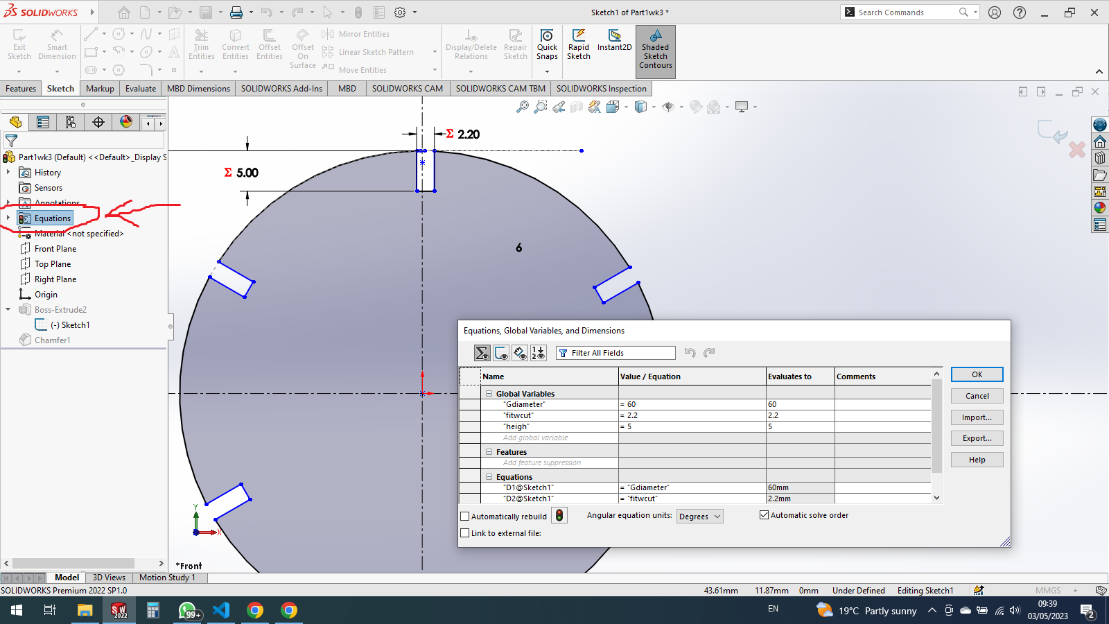
after choosing equation management then new windo opens including different parameters
the fist row contains the variable that i set so that i give it values
to demostrate what i mean, i changed variable from 5mm to 2mm and both changed together automatically
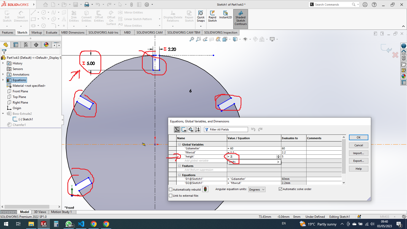
and here is how they changed according to the parameters i give them

i have used this parametric design to the other objects
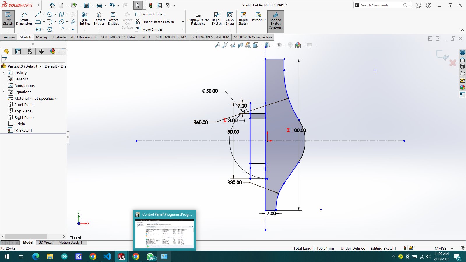
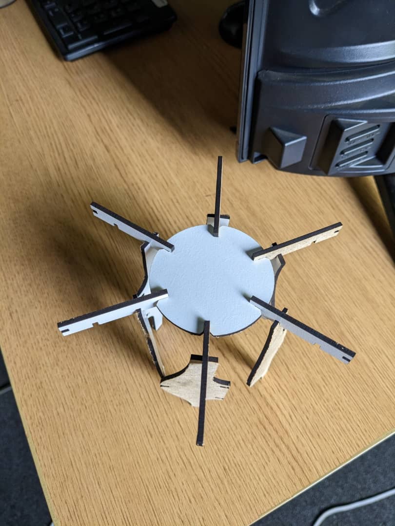
this circular object it is the first one that i made that could be placed anywhere, then next i designed another object that could fit the first object i made.
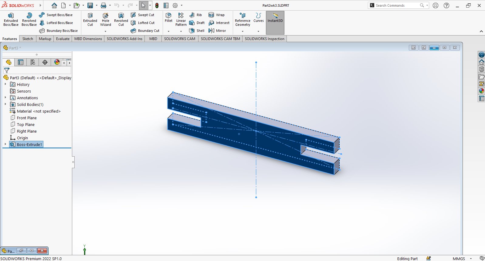
i started with sketch straight middle line and side circle to make round line, i wanted it to look fancier which can also be used to make multi functional fitting

then after making all the measurements i made slots that will be used as press fit as follows in the image
i made an extrusion to make it look more realistic
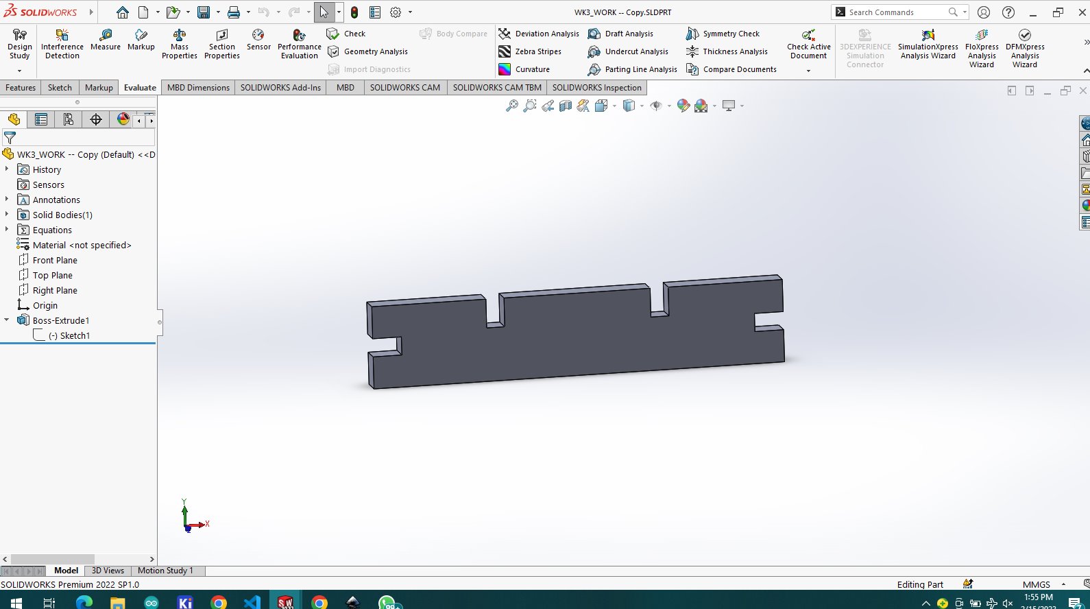
then the third object has the shape of rectangle that could be used as fittings and also they have slots
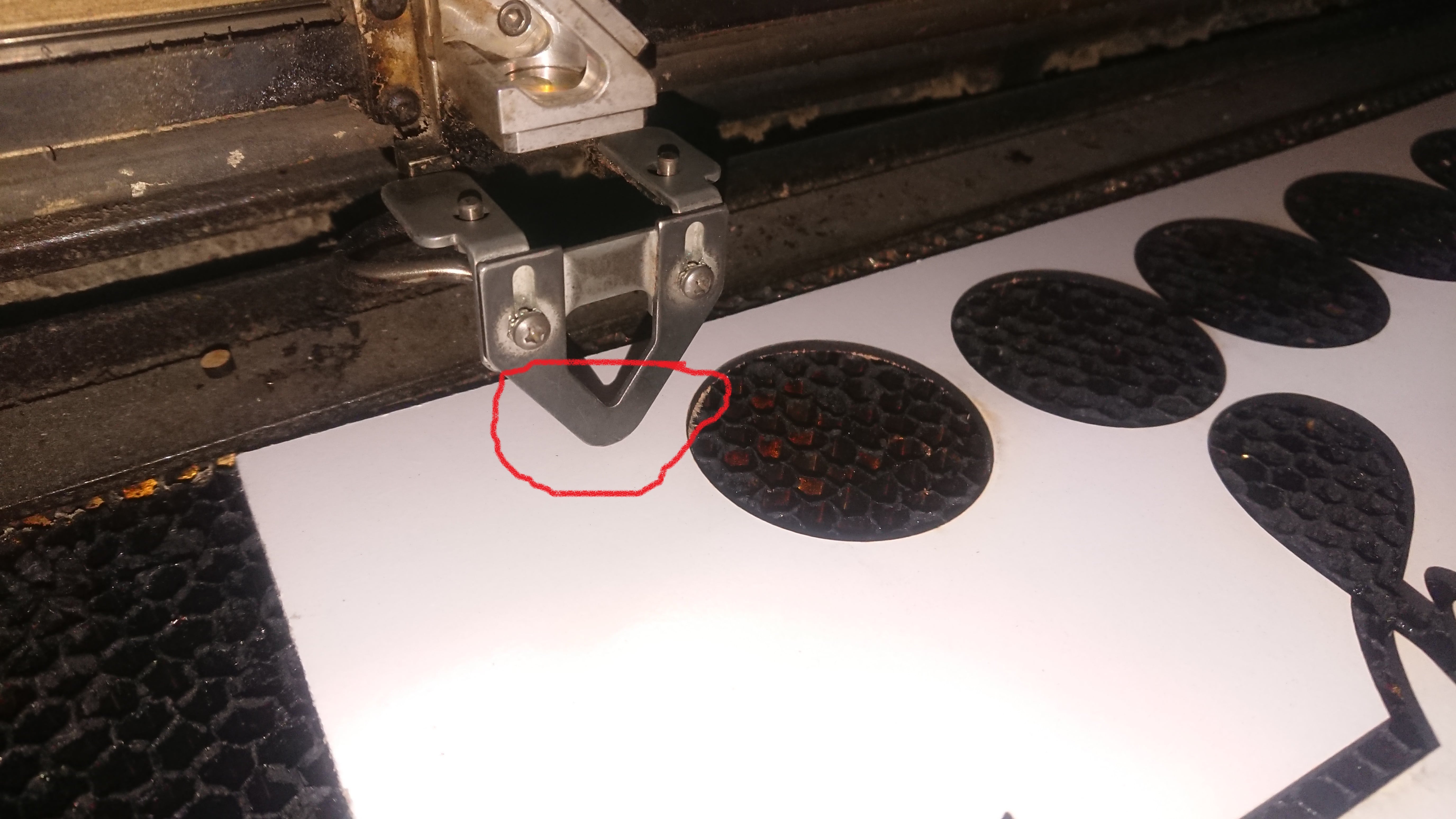
steps to laser cutting and engraving from our machine we place matrial to be cutted, though we set the height of the bed in order for the laser to set the actual focal point of the laser beam.
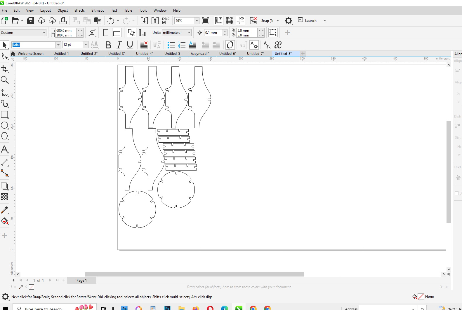
first i opened coreldraw and imported my files i generated from solidworks to generate vectors i needed 16 pieces in total all of them i aligned them all on the same sheet which fitted perfectly
i started moving bed up and down to calibrate laser focal point, where you calibrate until the tip of the tool touches to the material ready for cutting, this calibration helps not loose any amount of light
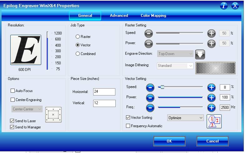
before starting laser cutting work i just pressed ctrl+p fro ptinting the new window opens
in this window configuration is where we set the speed of laser movement the power of laser cutting
selecting whether it is cutting or engraving all these parameters are configured depending on material for laser work either cutting or engraving
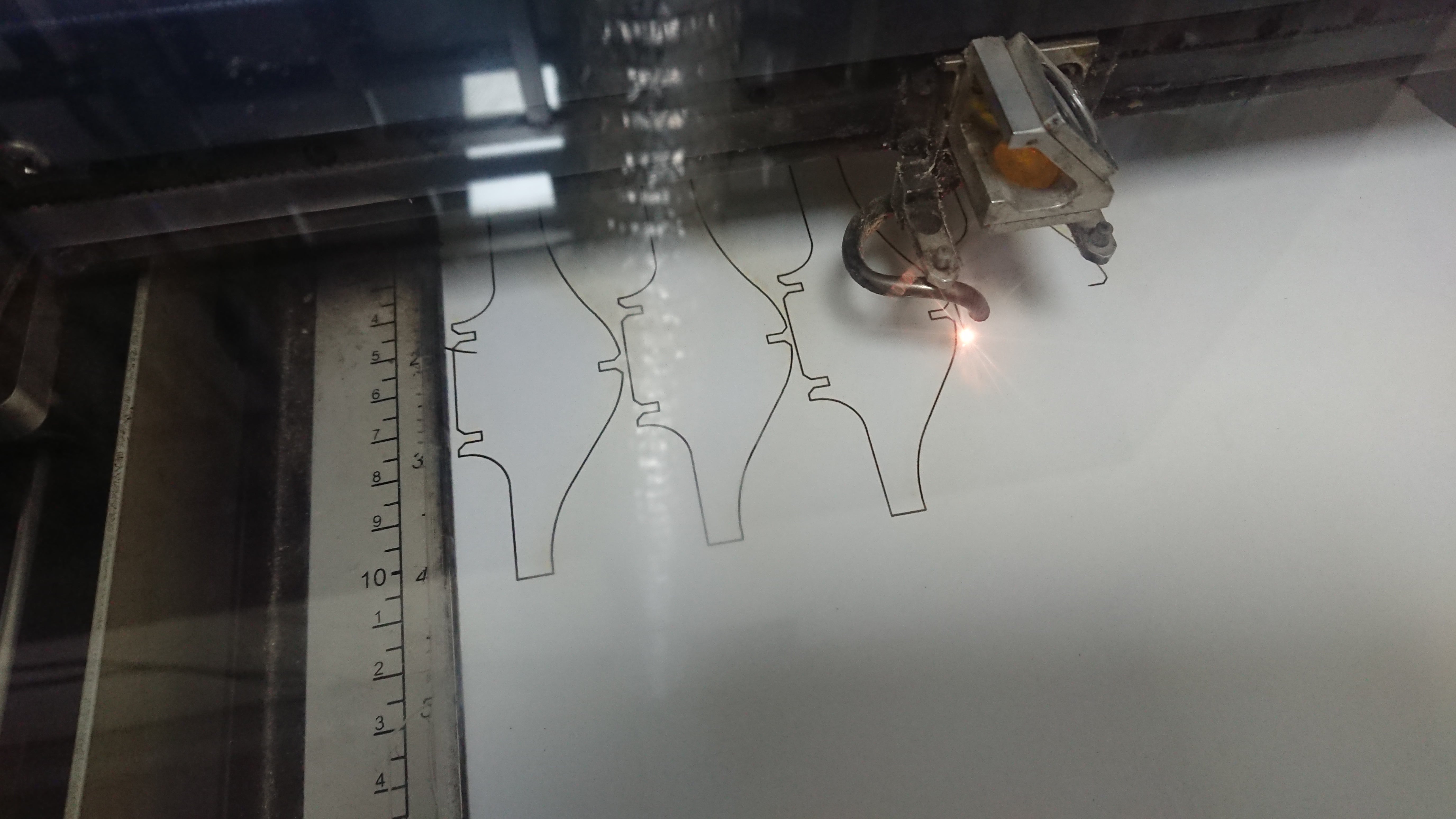
after cutting work is done then the output results here
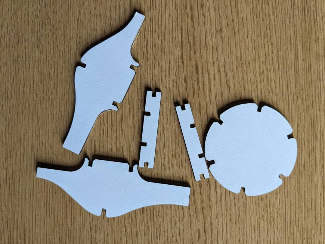
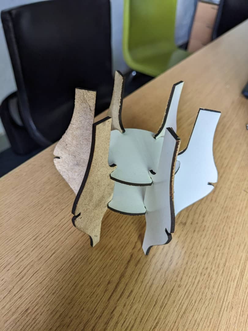
assembling cutted tools to build random view

vinly cutter
A vinyl cutter is an entry level machine for making signs. Computer designed vector files with patterns and letters are directly cut on the rollof vinyl which is mounted and fed into the vinyl cutter through USB or serial cable. more about vinly cutter click HERE
to make design and cut in vinyl cutter we needed some tools to make a cut
we need drivers which helps a computer to communicate with machine there are different machines and their compatible drivers in my case it is ROLAND CAMM-1 GS 24
visit their website "ROLAND" https://www.rolanddga.com/ to get drivers and software even more information
the secod tool i needed is designing software which helps to prepare an object to be cutted i have downloaded software called easy cut studio which you can get through HERE ROLAND CUT STUDIO overview
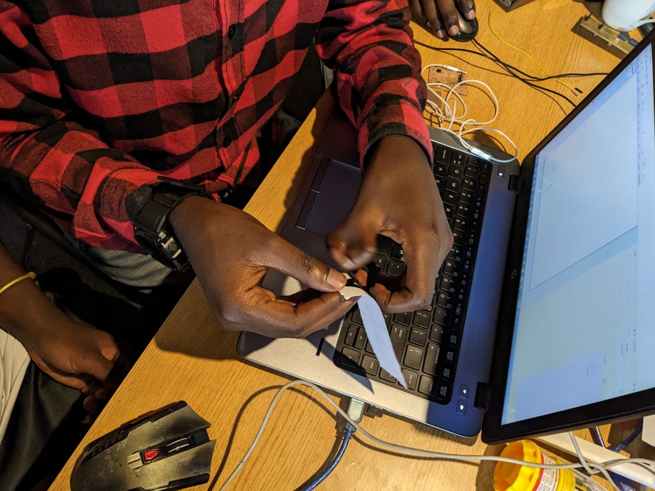
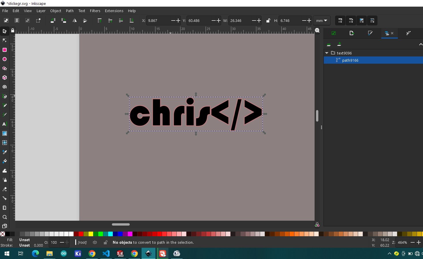
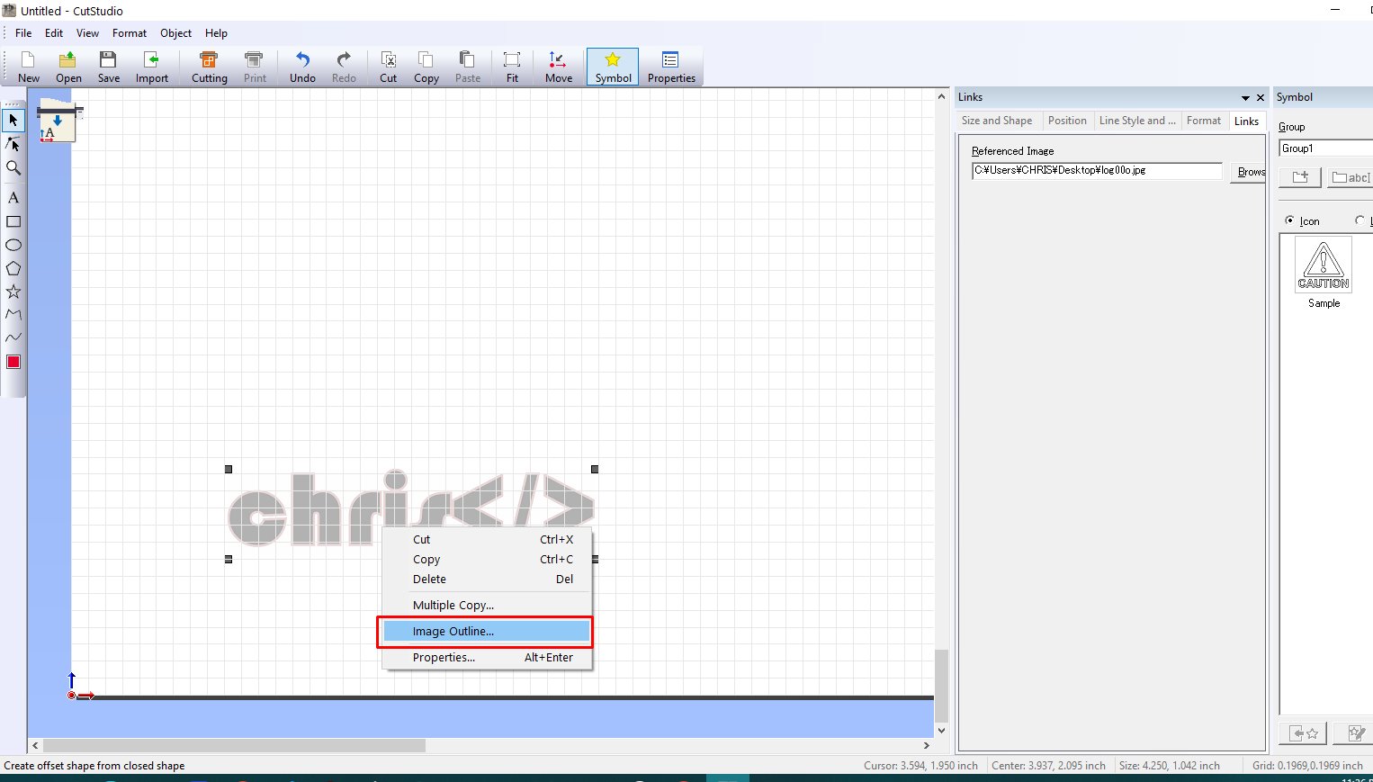
for using cut studio i start importing the pre made image made in inkscape i want to cut in vinly
right click on imported image and then choose image outline
from image outline we calibrate the imagege until we get all desired vector the okay
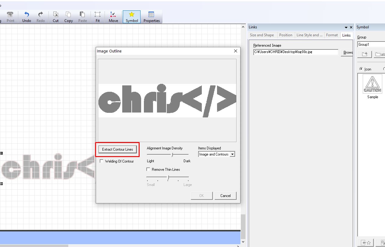
then when done click on extract contour lines to generate cutting line path
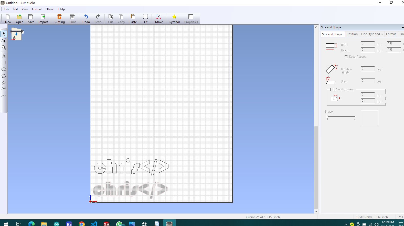
when done you see it is separate 2 files one is vector for cutting lines another is an normal image which can directly be deleted
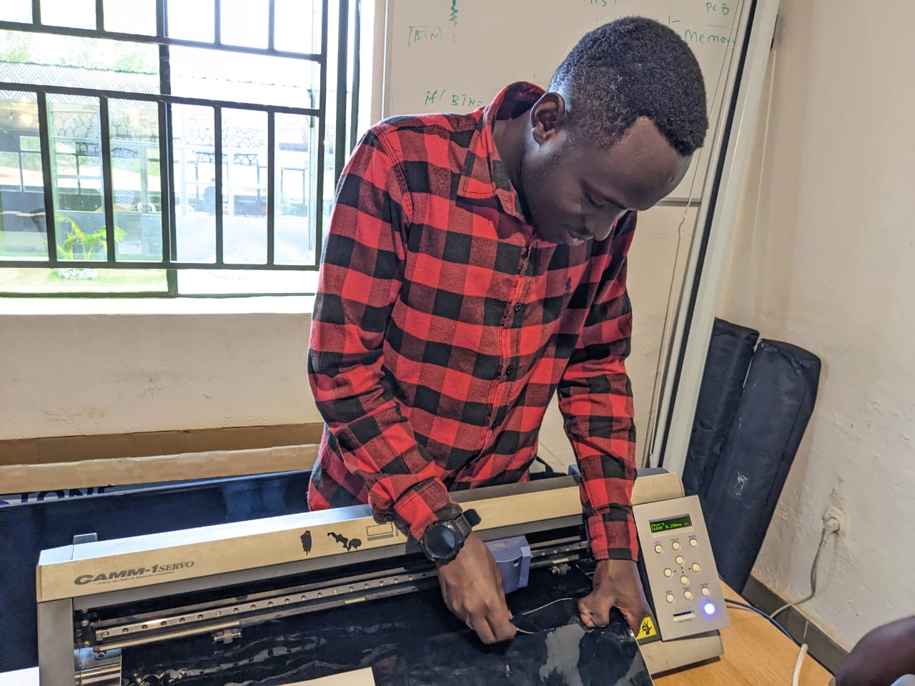
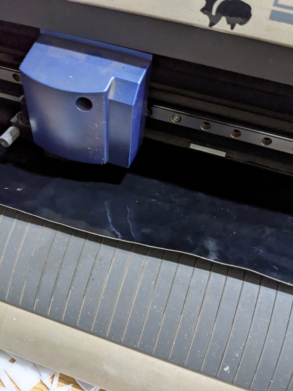
i started by inserting the sticker paper, but before cutting i set the the wide distance of the paper
there are two rollers that determine where machine sets where to start and the end dependingi on th size of the paper
the rollers are set by hands manually we push them on white marking on top of rollers then after i clink on machine roll the paper to see where we set as start and end
the machine will automatically roll and measure by itself


if you press enter on roll paper menu the mahine has the size of paper which helps us to set the distance in software for the first time before starting cutting i have to configure some parameters
by clicking cutting button
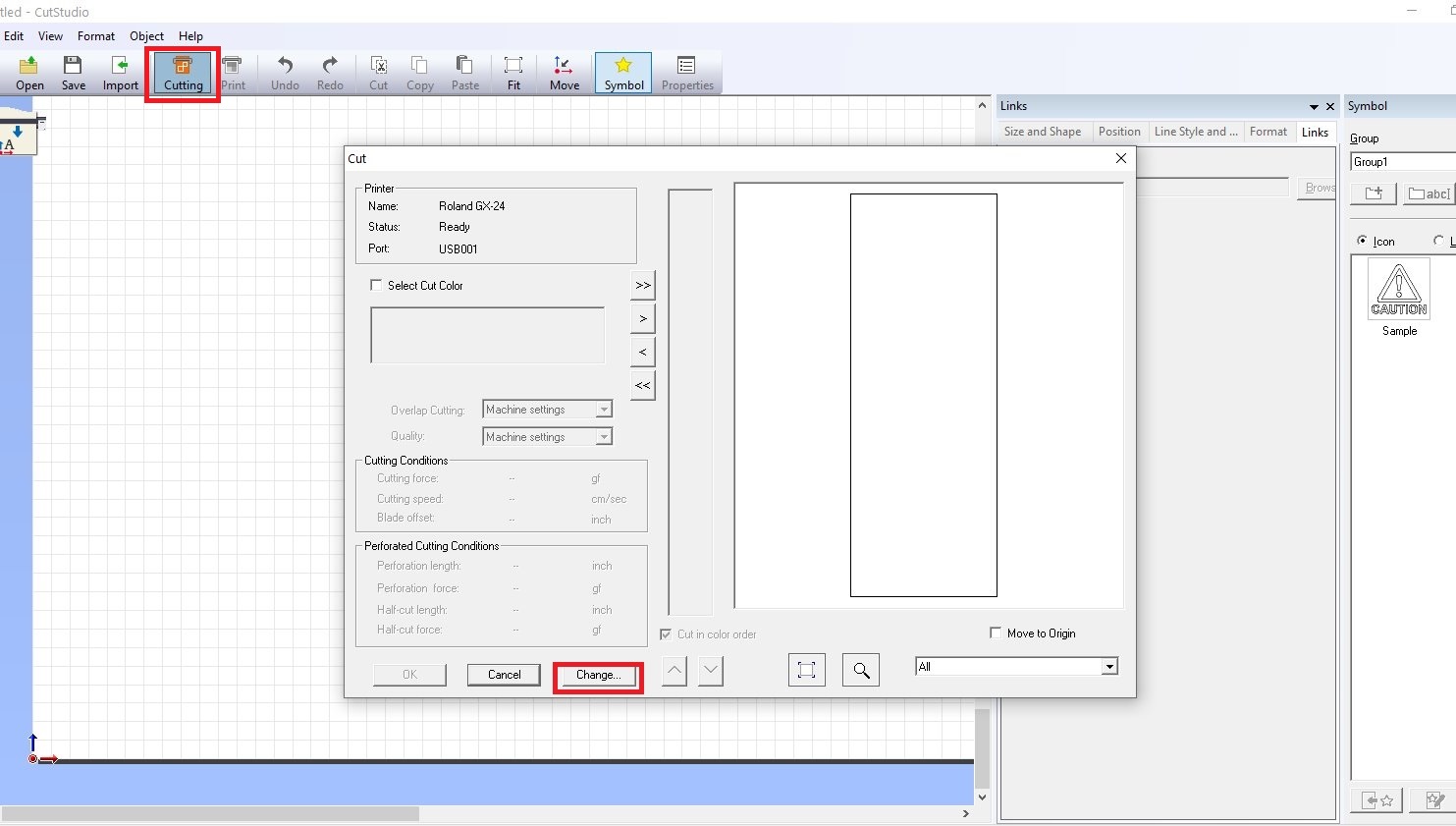
from dropdown box we choose the type of the machine we use so i choose GX-20 as our roland model
then after choosing machine model i clicked to property
i get cutting are from machine saved coordinates when i pressed roll the paper to determine the size of cutting area

i click to get from machine, it will directly get the data from machine that was measured before
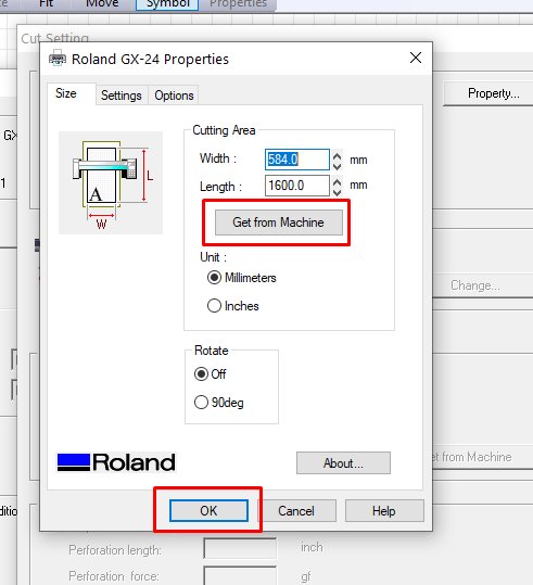
whe all set i click ok button the other paramers from machine settings, i let it as default and it started cutting
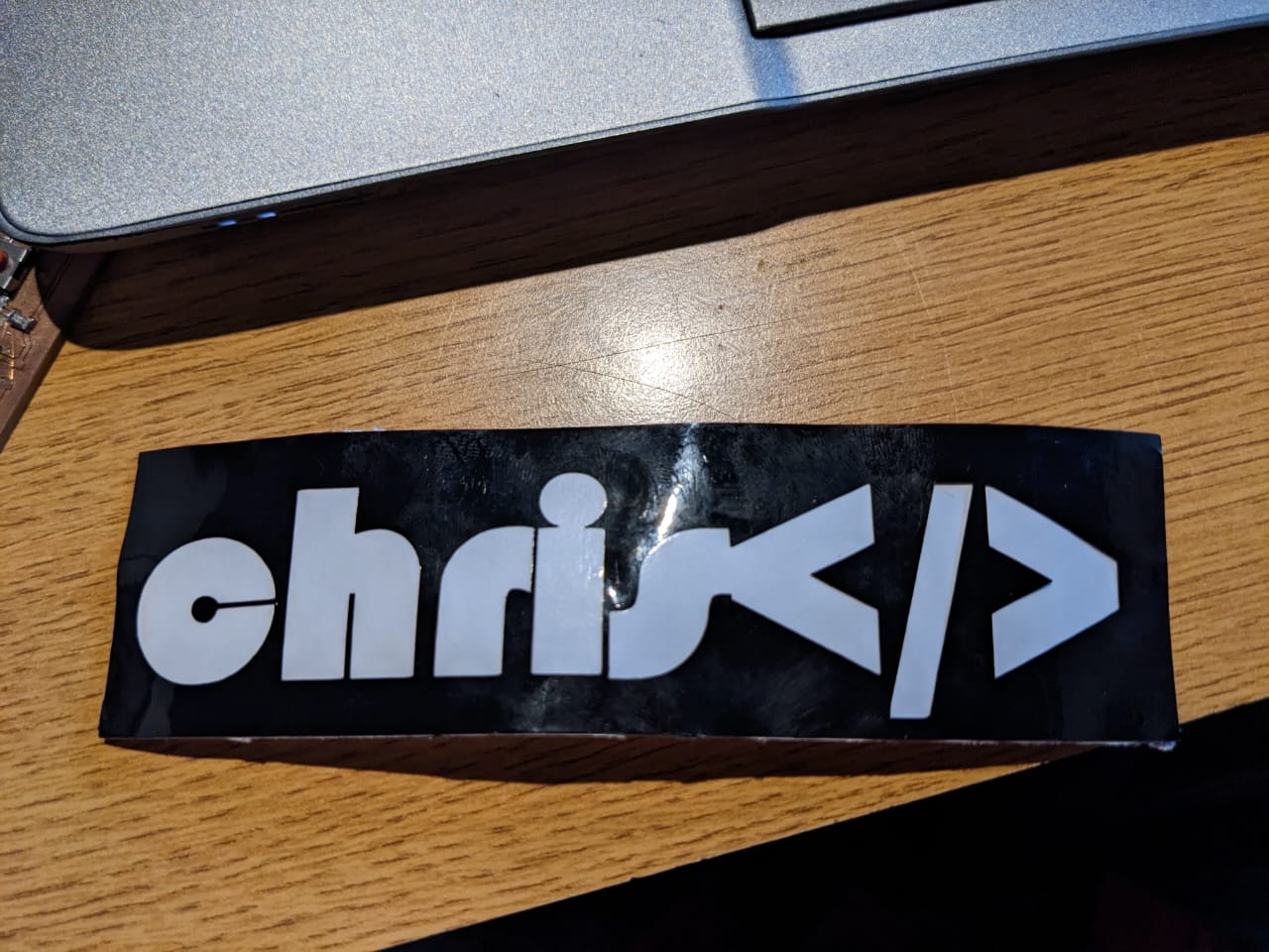
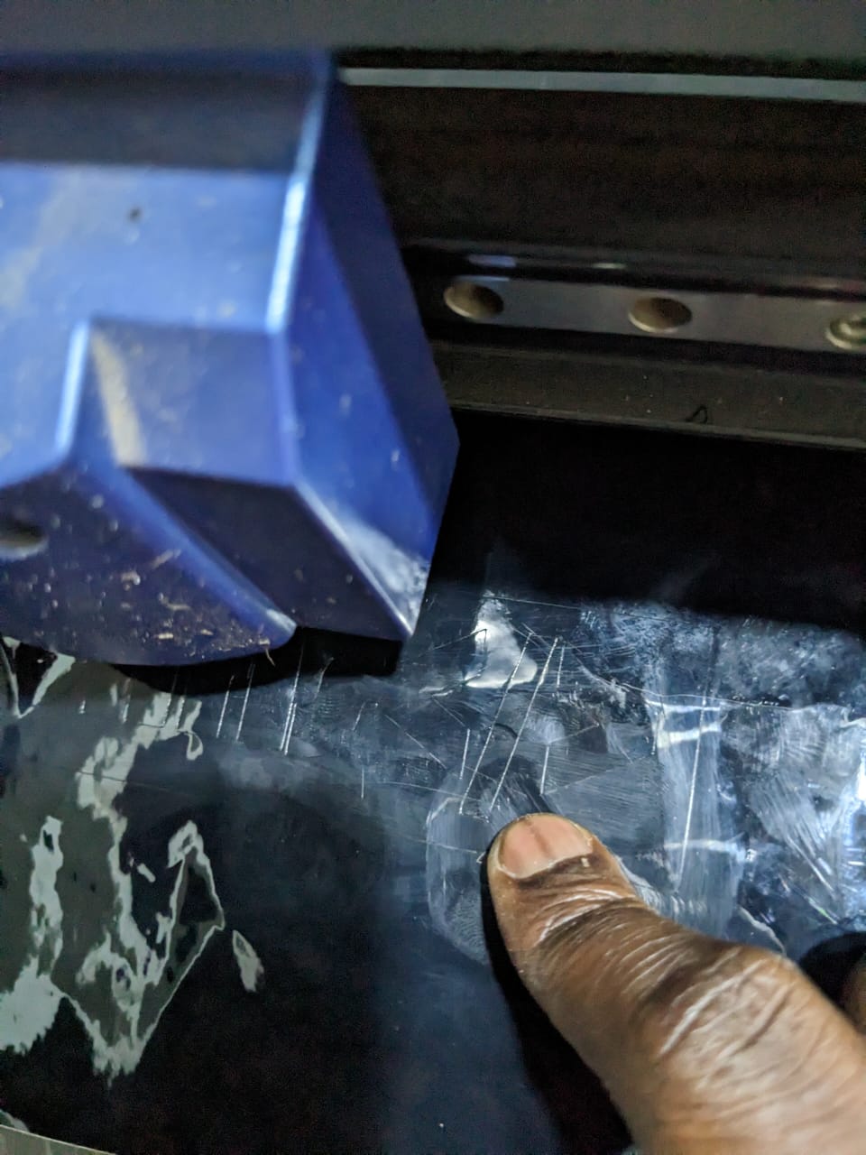
the first results came out are shown in image below

i realised that pen force was not suitable for the paper so it scratched my paper i had to reduce the force to see the results again
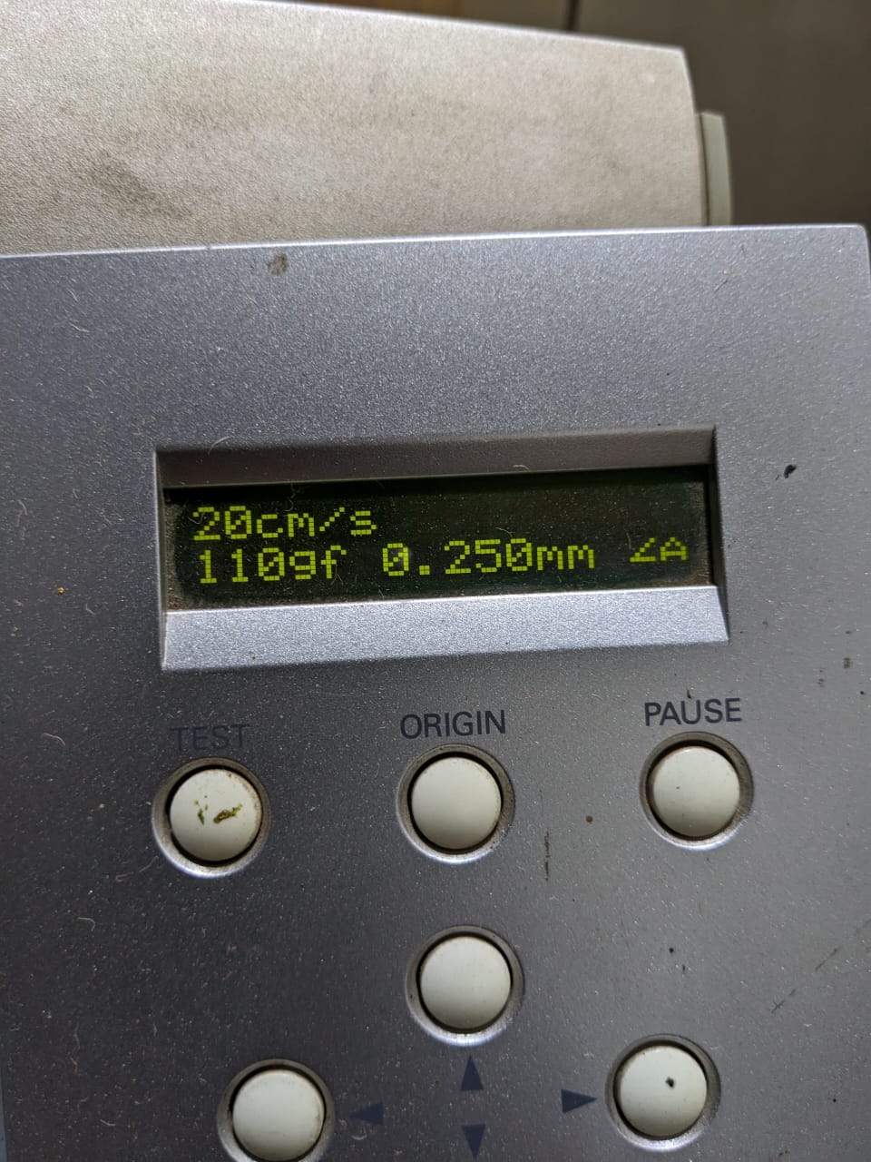
i changed it from 130gf to 110gf and the results again
and again somehow it didn't go well again
after changing the force the machine worked properly but the sticker didn't seemed cutted well but the marking was there on the sticker i kept finding solution
so i realised that manual slider pen force udjuster was not stable for some reason so i started calibrating the slider to find the right spot
at last point it was set above 1 and then i slided back little bit below 0
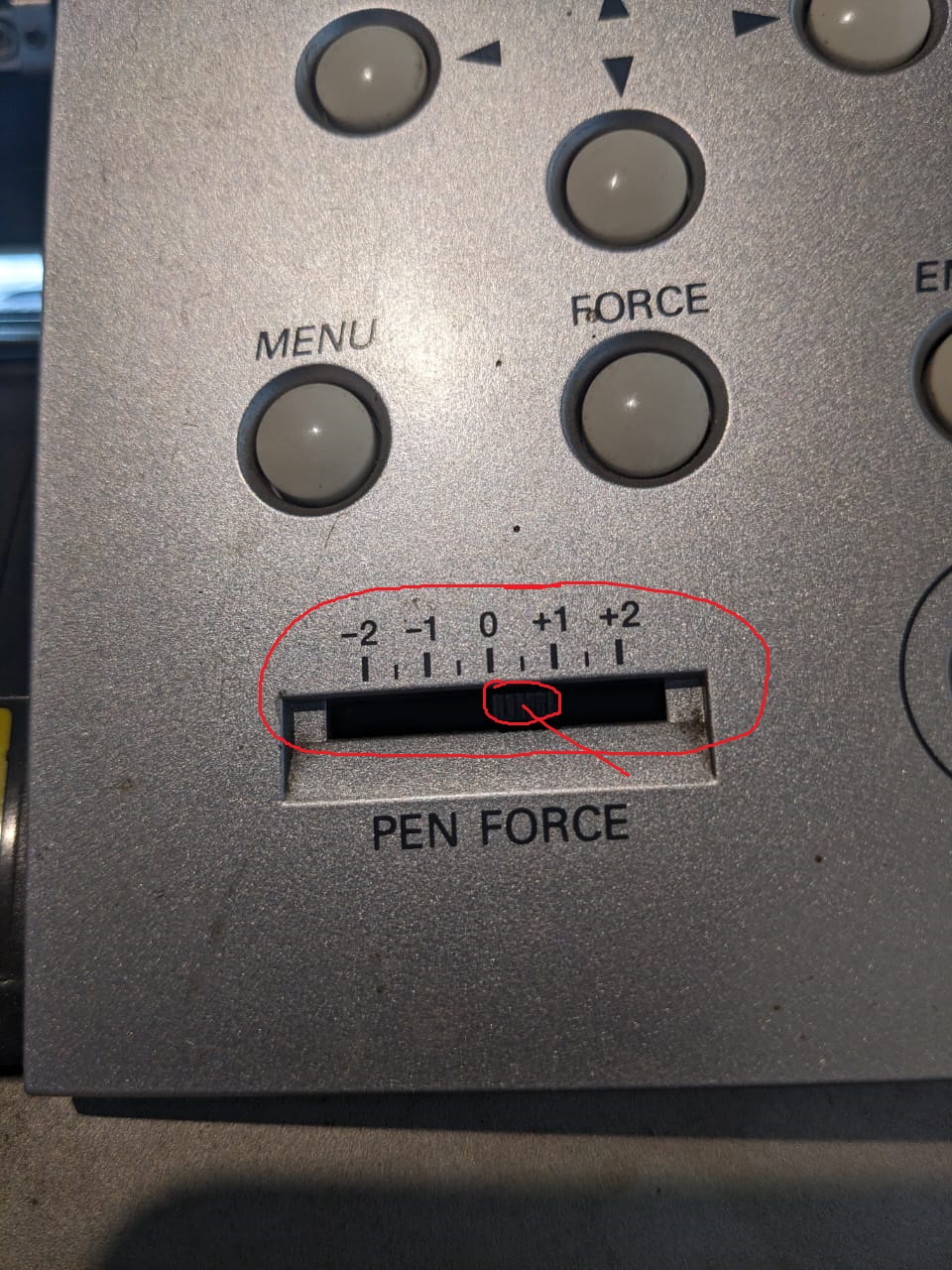
after calibrating the tool the results comeout successfully