5. 3D printing and scanning
For this week, it is 3D printing and scanning. 3D printing is one of my favourite things to do these days. Infact I defended my masters thesis on how 3D printing can help explore parametric designs for 3D printed architecture in coming future. This week's assignment is to design and 3D print an object that could not be made using subtractive or formative manufacturing. And also to scan a 3D object and optionally print it. Before we dive into the assignment work, let's first understand some basics of 3D printing as an additive manufacturing technique.What is 3D printing
3D printing uses computer-aided design to create three-dimensional objects through a layering method. Sometimes referred to as additive manufacturing, 3D printing involves layering materials, like plastics, composites or bio-materials to create objects that range in shape, size, rigidity and color.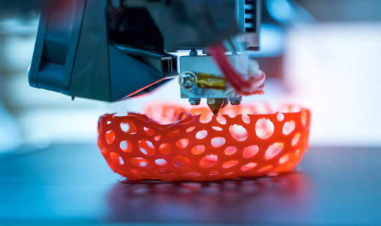
Additive v/s Subtractive v/s Formative Manufacturing
Let's first get clear with the difference between addivitive manufacturing, subtractive manufacturing, and formative manufacturing. Additive manufacturing is the process of creating an object by building it one layer at a time. It is the opposite of subtractive manufacturing, in which an object is created by cutting away at a solid block of material until the final product is complete. Manufacturing has gone through a series of major evolutions in the past few years. Subtractive processes (drilling, cutting, CNC milling and turning) and standard formative techniques (injecting, foraging, stamping, casting, molding) have been challenged by new, rapidly growing disruptive technologies, including 3D printing, laser surface texturing and additive manufacturing, among others.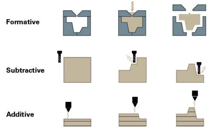
Let's start the assignment
So for 3D printing part of the fabacademy assignment for this week, I worked on trying to solving a very niche personal problem about cable management in my bag.Basically, every one of us might have been through this that our type C or whatever power cable gets entangled in itself and ends up damaging the cable itself. I have had this issue recently and that's when I had thought to solve it out with some cool design.
Design
So the 3D printers only understand gcode files. And these gcode files can be made of softwares like Ultimaker Cura, Prusa and Fractory. Basically these softwares are designed by the 3D printer companies and are obviously suitable to be used for the specific printers. SO if you want to print on a Ultimaker printer then designing the gcode file of cura is the most optimum thing to do. But before that, these softwares can open only .stl or .obj files.What is an .stl file?
STL is a file format commonly used for 3D printing and computer-aided design (CAD). The name STL is an acronym that stands for stereolithography — a popular 3D printing technology. You might also hear it referred to as Standard Triangle Language or Standard Tessellation Language. Each file is made up of a series of linked triangles that describe the surface geometry of a 3D model or object. The more complex the design, the more triangles used, and the higher the resolution. You can recognize an STL image by its .stl file extension and by its lack of color and texture.
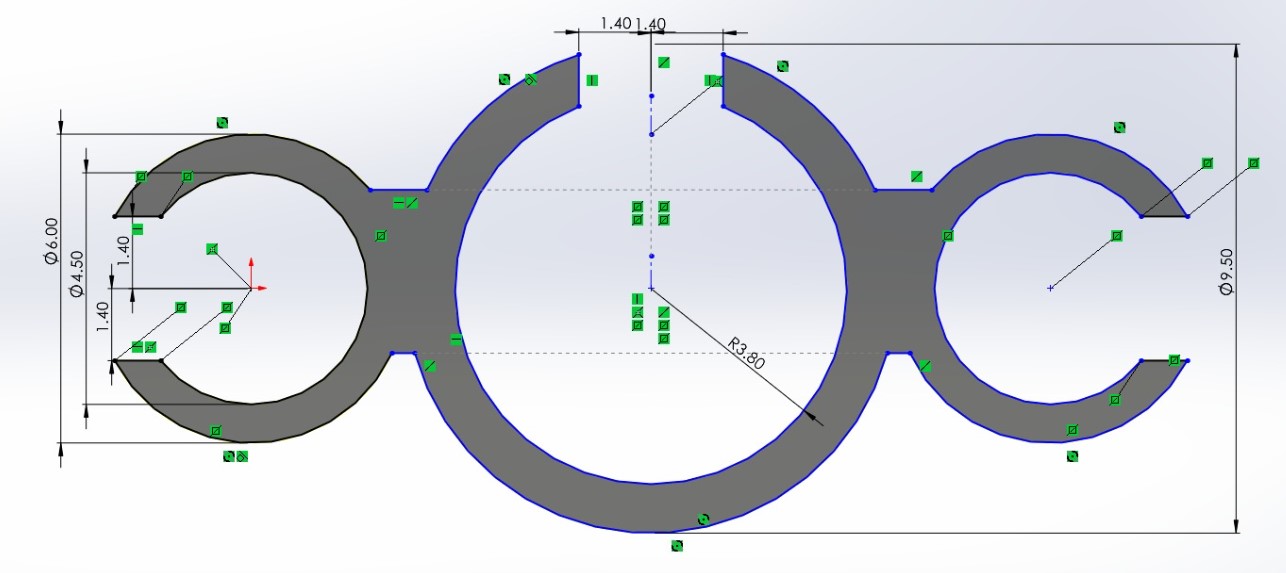
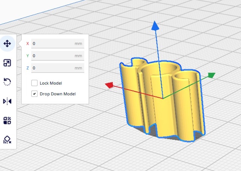
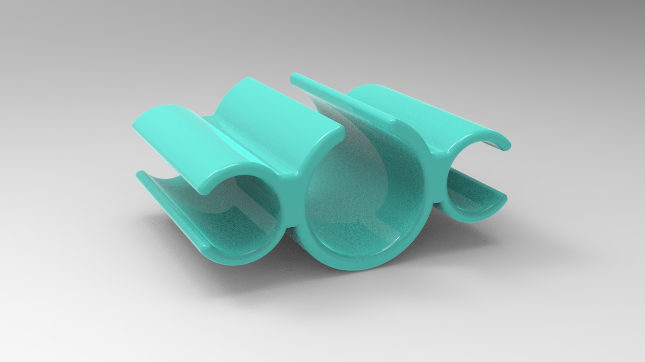
So design a cable management system for my phone charger, I had already visualised a curvy design. And based on which I was sufficiently confident enough that it can't be manufactured using subtractive manufacturing technique and most likely it is also difficult for formative manufacturing because of the curves I am assuming to achieve. But let's see how it goes.
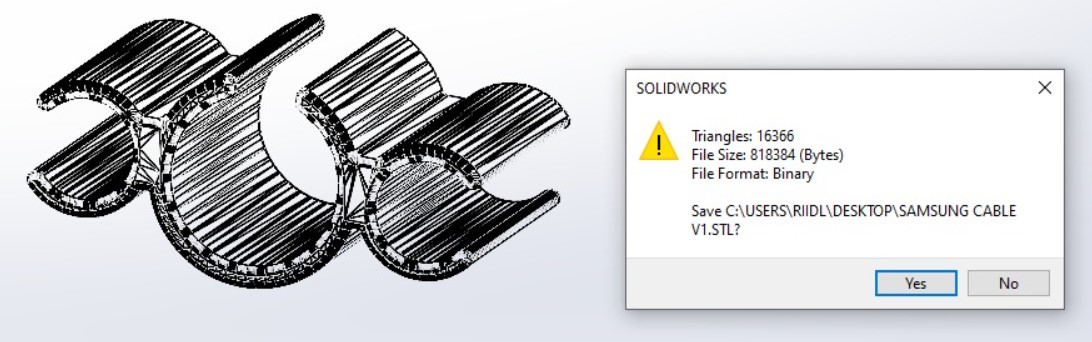
First step was to measure the cable diameter using vernier caliper. And also estimate the number of loops of the cable to be adjusted within the holder. Based on that, I designed the file in solidworks as shown in the figure below:
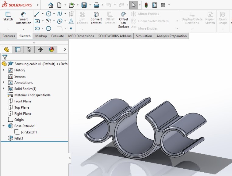
add steps for sketching >>>>>>>>>>>>>>> I designed it in such a way so as to avoid extra supports. The design file is supposed to be exported as .stl file as shown in the figure below:
.stl to .gcode file
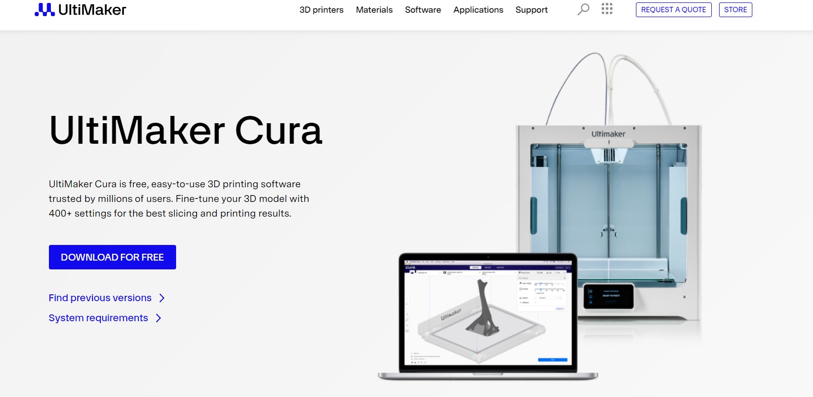
Step 01: Installing Ultimaker CuraSo I used Ultimaker Cura software to convert the stl file into gcode file. Ultimaker Cura is a free software and can be installed from the official website as shown below:
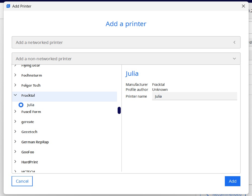
Step 02: Setting up your printer
Once the software is installed, you need to setup your printer settings to it. If your laptop is connected to the printer then you should be ideally able to see the printer in the dialogue box. If not, then you can also setup a non-networked printer by choosing the exact name of your printer from the list as shown below:
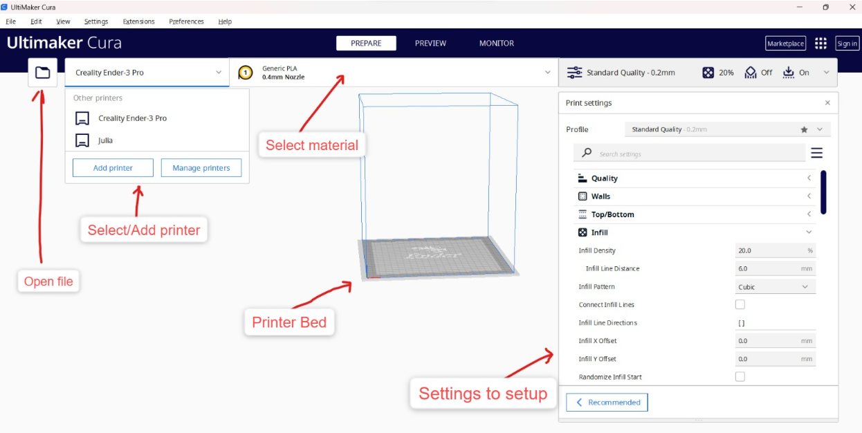
Step 03: Understanding the interface
Few basic settings of the welcome interface are shown below in the image.
Step 04: Importing the file and setting up on the bed plate
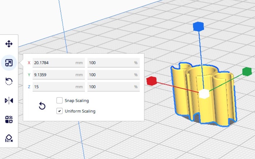
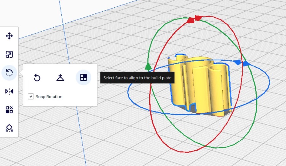
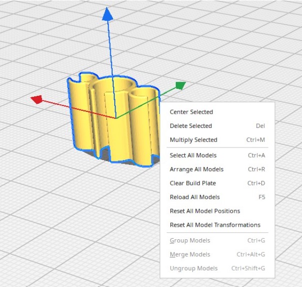
Once you import the file from the tope left icon option, the product can be seen on the bedplate. The software drops the product based on its intelligence and now you can adjust its placement and location based on your design. Basic options like translational motions in 3 axes and rotational motion in 3 axes, scaling the product, etc can be done from the panel shown below in the images. Apart from this, you can also just select the base you want to snap to the bed plate and directly snap it. You can also multiply objects here, or center align the product and many more by selecting the product and right clicking to see additional options possible.
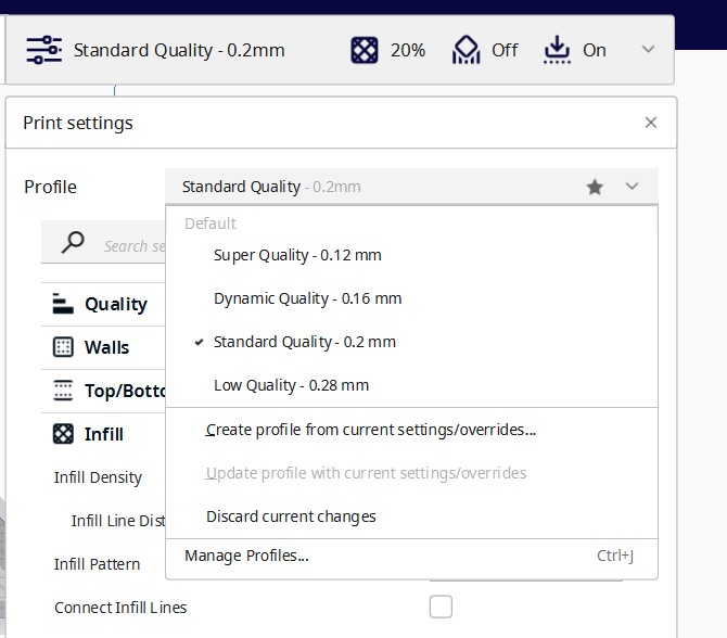
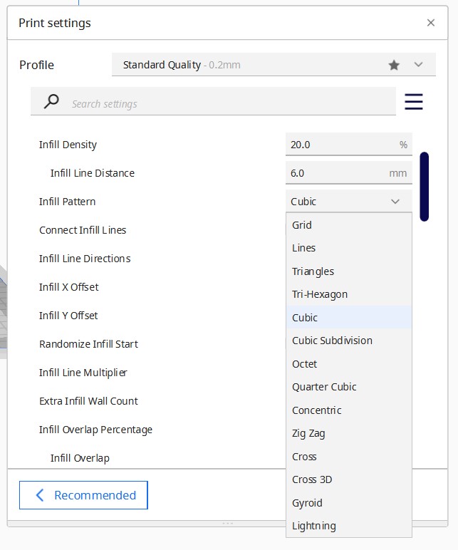
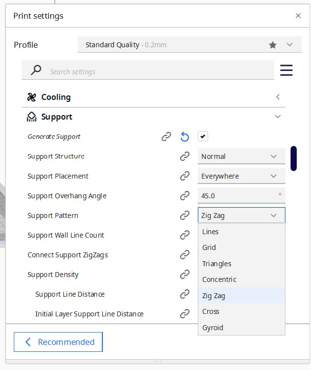
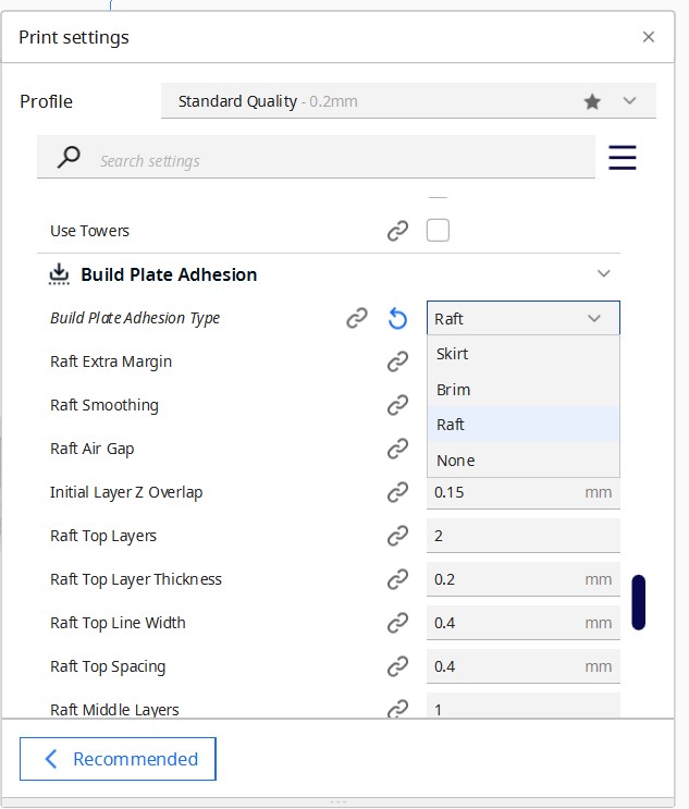
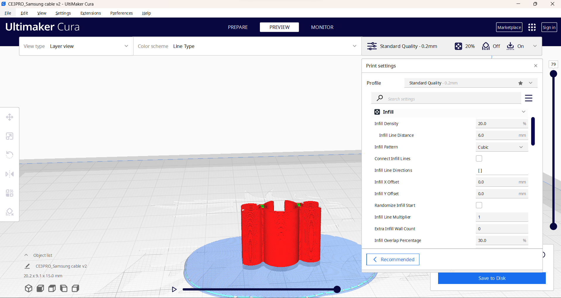
Step 05: Print settings
For print settings, you need to choose profile quality first. The basic settings I used were standard print settings 0.2mm quality, 20% infill density, cubic infill pattern and raft suppport for bed adhesion (knowing the efficiency of my printer with other bed adhesions)
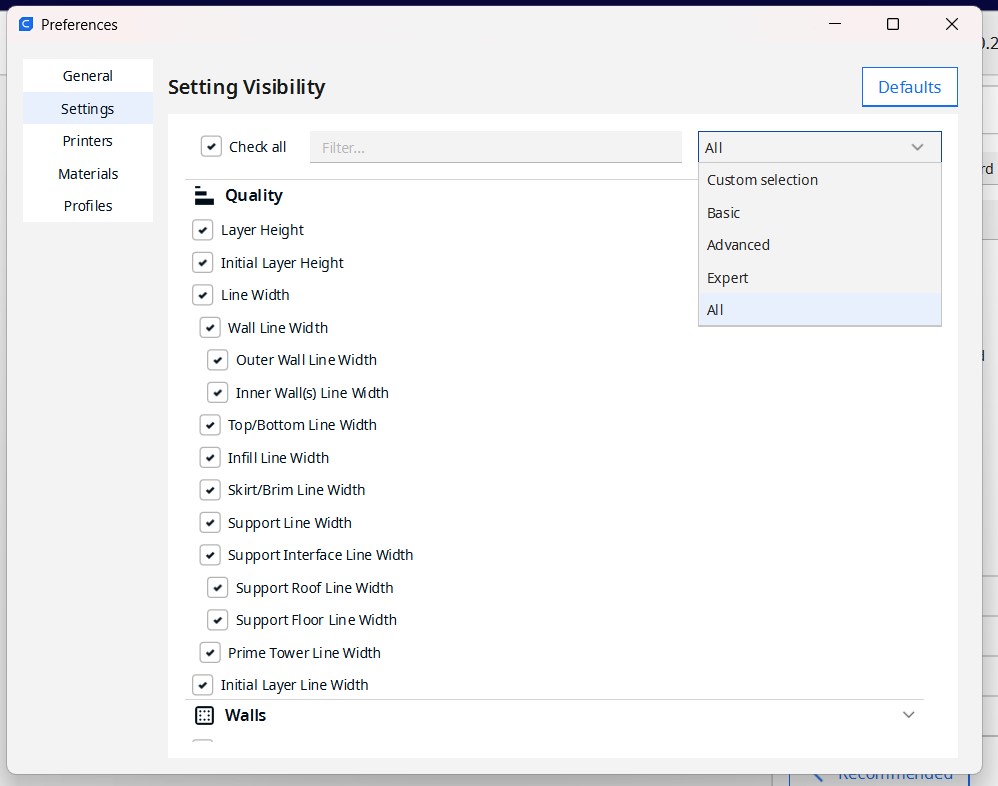
I just realised that these many advanced settings might not be visible when to start Cura for thr first time. So if that is the case, you need to go in Preferences > Configure Cura > Settings and then change the dropdown option to ALL from BASICS.
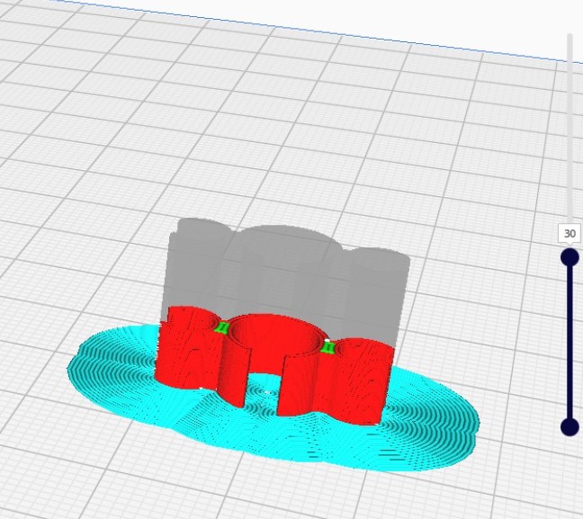
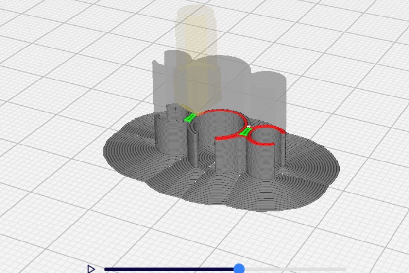
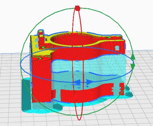
Step 06: Preview
Once these settings are set, we slice it by clicking thew slice option on bottom right. It takes some time here if the file is heavy and then it shows a previw of how it will be printed. YOu can see the preview by going into the preview window and scrolling down the process from the extreme right scrolll bar.
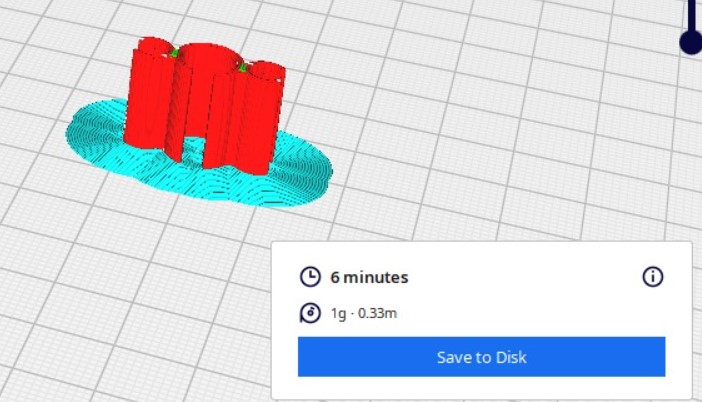
Step 07: Export gcode file
Once everything is checked and fine, we can export the gcode again from the bottom right window. It also shows the estimated time it will take and the mass in grams of PLA it will utilise. Accordingly you can set your printer ON and choose the material reel to use if it is a big file.
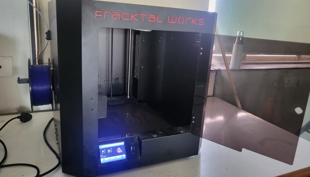
Step 08: Start the print
Now you take the gcode in a pendrive(usb stick) or just connect your laptop directly to the printer via usb cable. Then you can download the file locally in the printer or even just print it through your pendrive as per your convinience.
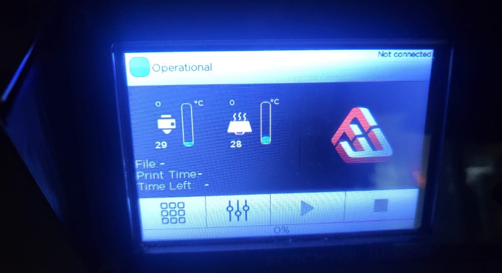
Step 09: Printer settings
The printer interface looks like shown below:
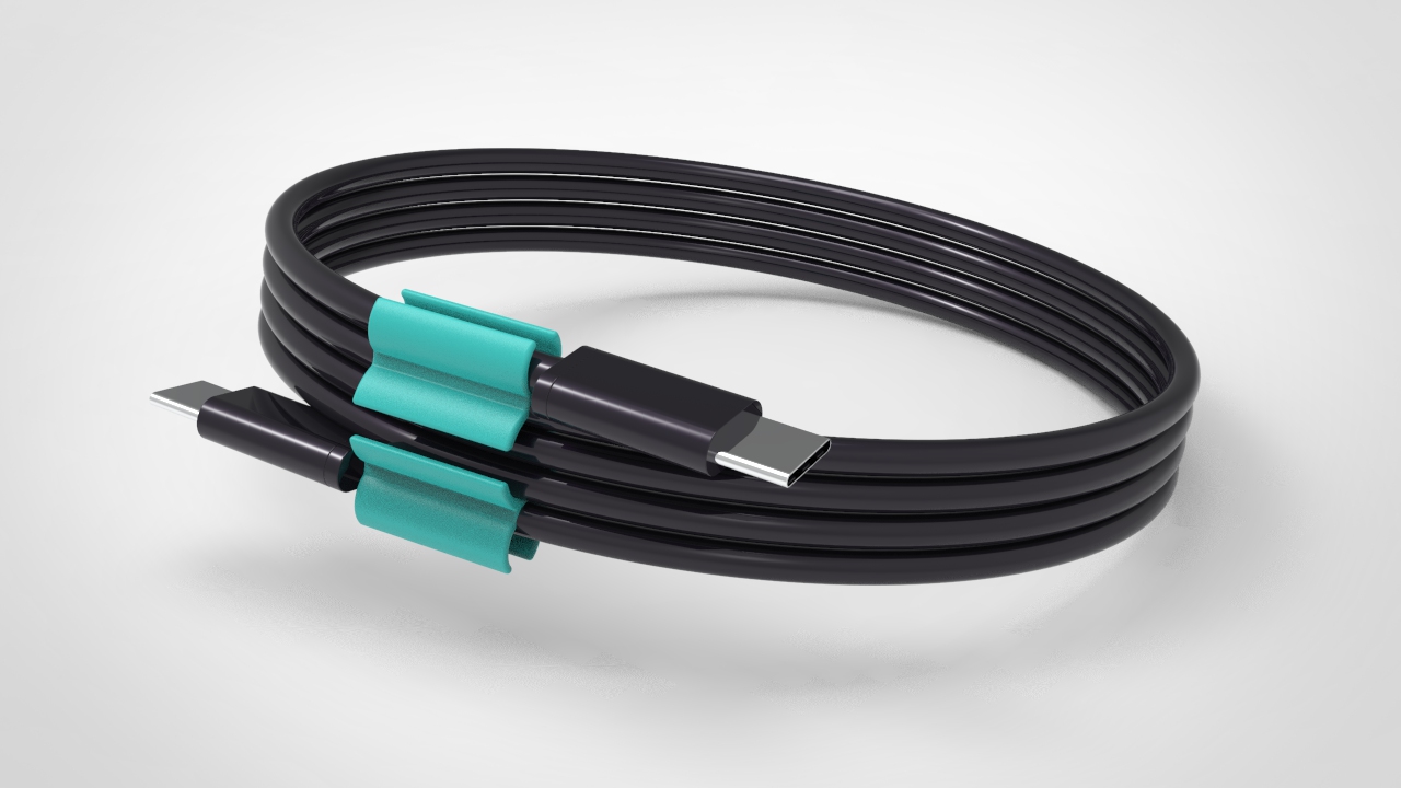
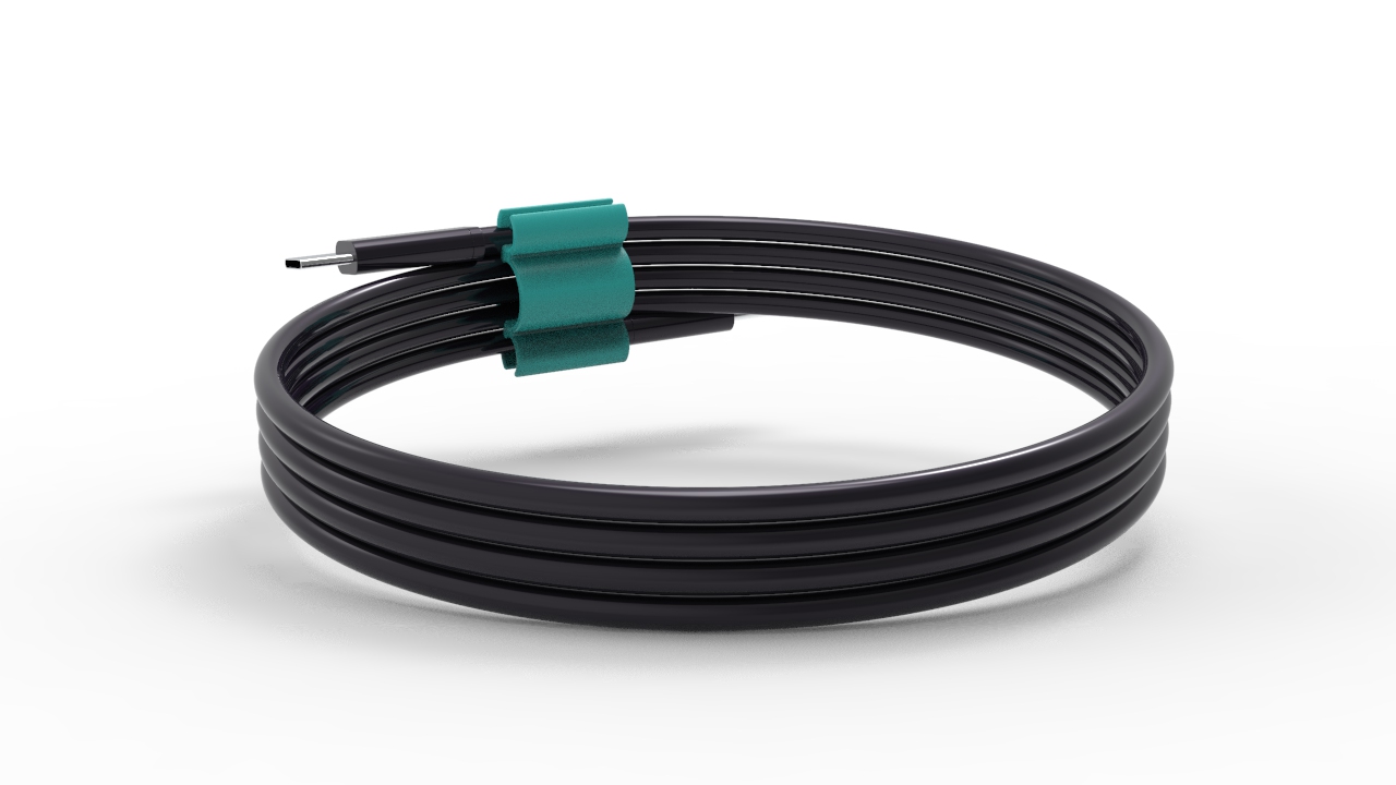
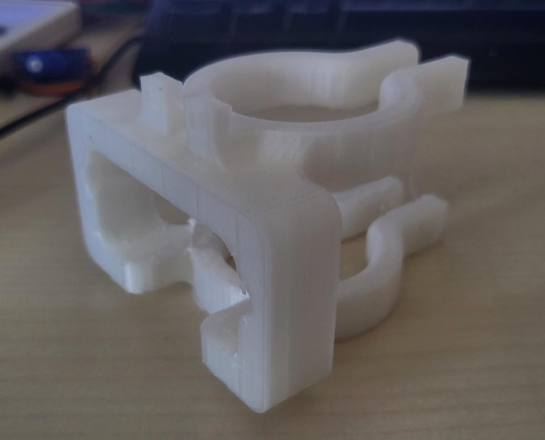
Final product:
For fun renderings, I used Keyshot software. The render of the final product is as shown below:
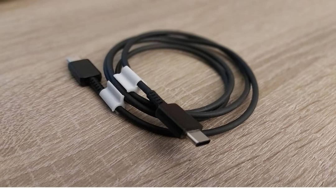
For more realistic representation, I used GRABCAD open source space to download a type C cable design and use it with my part design to showcase in real sense the use of the product. These renders as shown below are also rendered on Keyshot, and edited/adjusted on SolidWorks.
What is GrabCAD library?
GrabCAD has always been a community where engineers and designers can share their CAD models, find inspiration for new concepts, and download parts to advance their product design process. The GrabCAD Library offers millions of free CAD designs, CAD files, and 3D models. You can have an account at grabCAD and download standard design files to save your time.
3D printing assignment 2.0
Couple of weeks later, I realised that the design I 3D printed is not that difficult to be produced using subtractive or even formative technique. But then the custom designed holder for my final year project is definitely not possible to manufacture by anything other than additive manufacture. The design was made in solidworks as shown in the video below: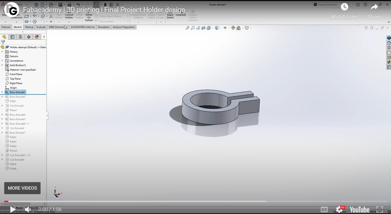
The reason why this design can't be manufactured using subtractive manufacturing is because there are holes in different planes and the design also has suspended arms. THe design is also complex for a formative technique as the mold was the same is very difficult to design even when bisected in the center.
3D scanning
3D scanning is a process of analyzing an object from the real world, to collect all the data in order to recreate its shape and appearance, digitally. There are a lot of different 3D scanning methods, but, we will focus on three of them, that we can consider as the main ones: Laser 3D scanning, photogrammetry, and structured light scanning.3D Scanning using EinScan One Handheld Scanner
riidl FABLAB has a handheld portable scanner - EinScan Pro HD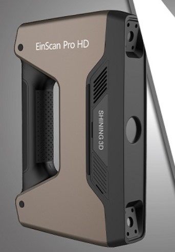
About the Scanner:
EinScan Pro HD has a dramatic breakthrough in scanning capability, processing up to 3,000,000 points per second under handheld scan mode, and less than 0.5s for every single frame in Fixed Scan Mode EinScan Pro HD is capable to scan a wider range of objects of dark or black color and casting metal surface, enriching the capability for 3D scanning of materials.
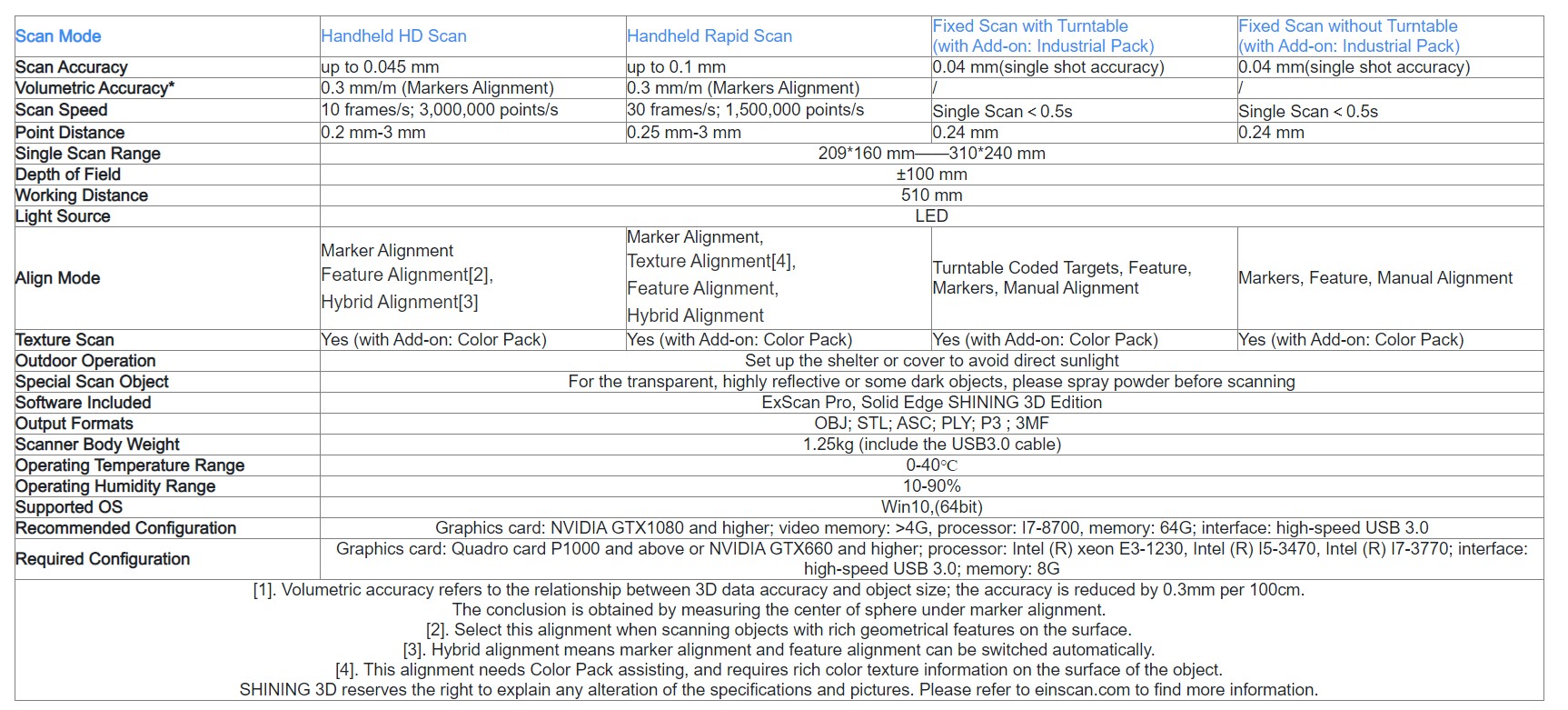
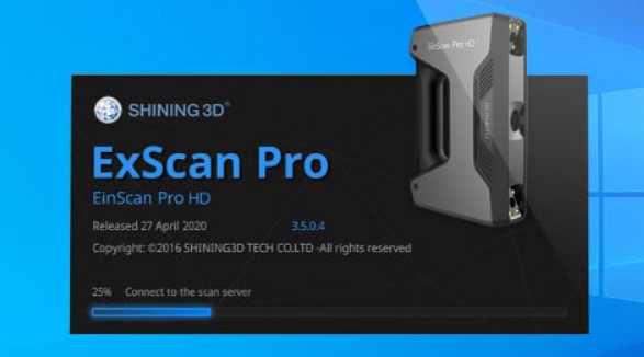
To use the scanner, we need to install the ExScan pro software as shown below: ExScan Pro is a professional software for 3D scanning and data processing with a collection of both scan and mesh editing tools for generating high-quality 3D models.
Let's start with the process:
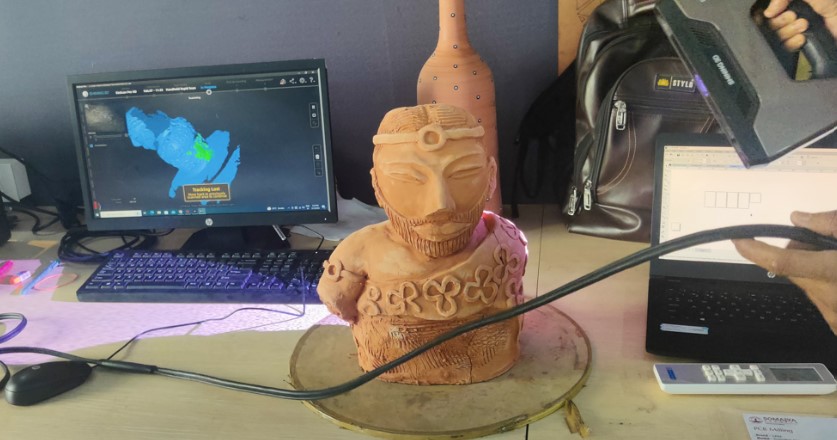
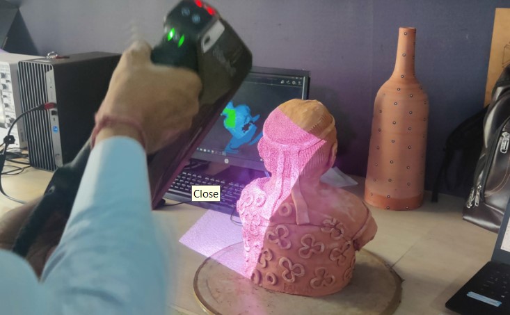
Step 01: Getting the object ready
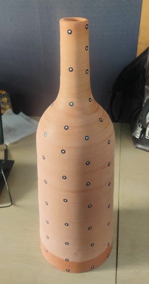
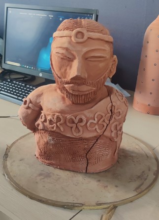
So we scanned multiple objects to explore the process. Here's the two prominent ones. We also scanned each other.
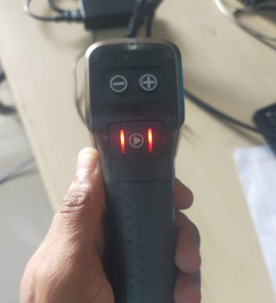
Step 02: Getting the 3D scanner setup
Turning on the device and the UI (buttons on the device) are pretty intuitive. One can easily understand how it functions in one go as shown in image below:
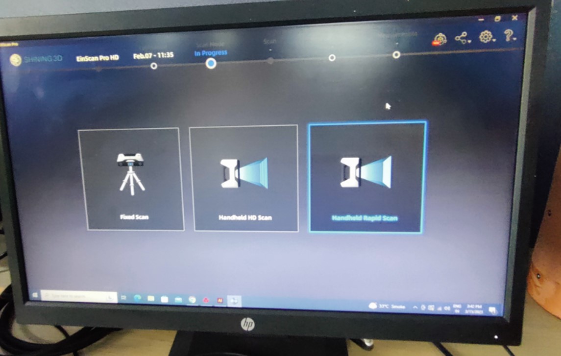
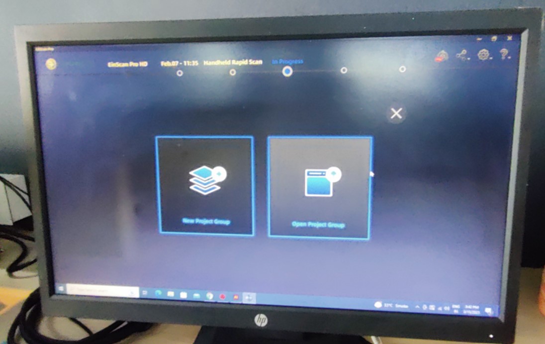
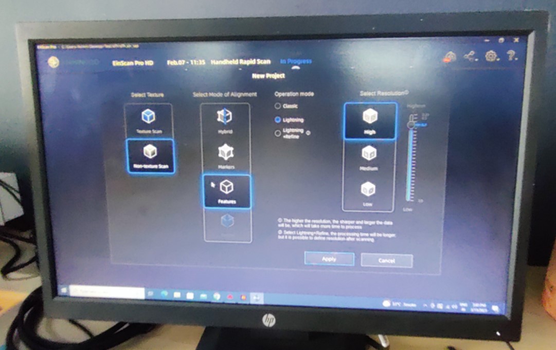
Step 03: Knowing the Shining 3D software
Now once the device is ready, with start with a new project in the software, then we choose the handheld rapidscan option, select high resolution option, mode of alignment and other options as shown in the images below:
Step 04: Starting the scan
Then just start scanning by slowly moving around the object with the scanner as shown below:
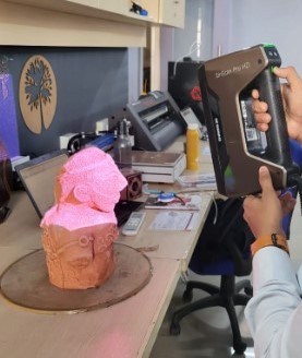
Step 05: Covering all sides
The screen reflects the scanned parts in real time with few seconds delay. We rotated the object and continued scanning to make sure we cover all the sides and angles.
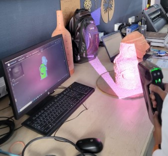
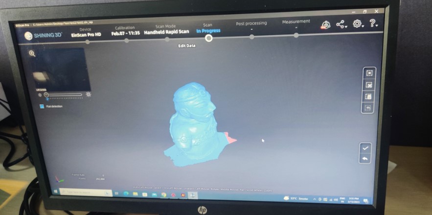
Step 06: Finding Blind spots
We then browsed through the scanned file to find blind spots that we have missed. It shows red if it is not being scanned or just shows the object as hollow at that point.
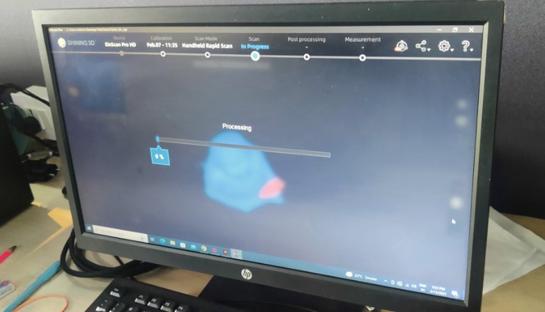
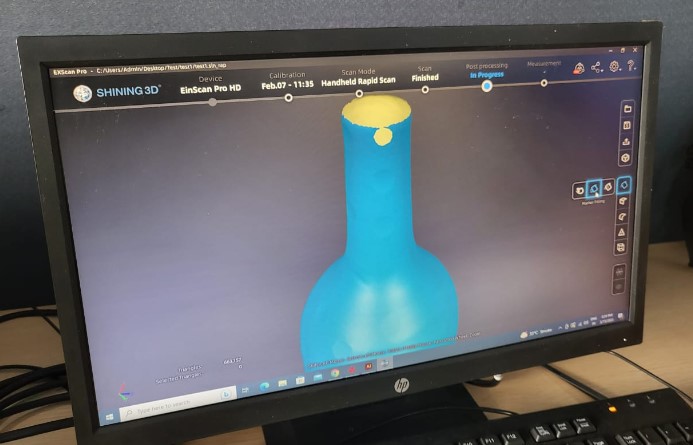
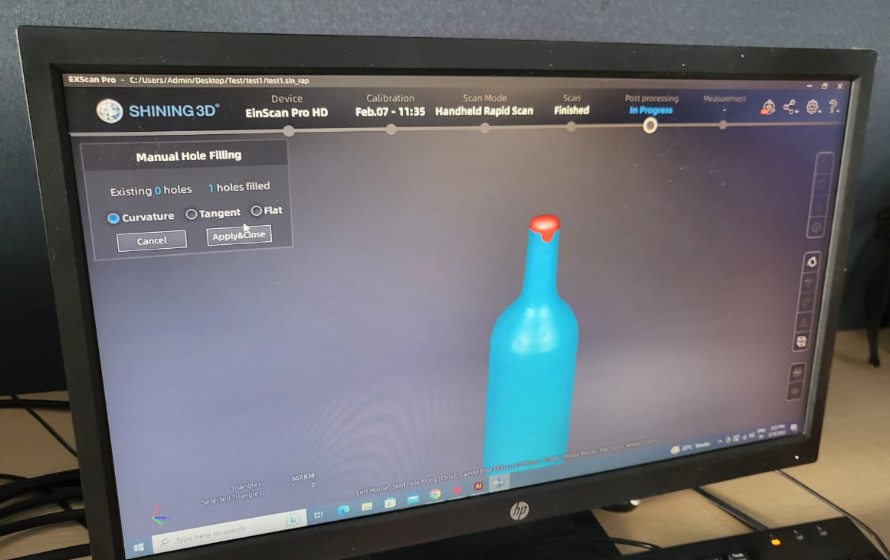
Step 07: Post processing the data
Once the scan is complete, we post process the data with some fixings to the inaccuracies.
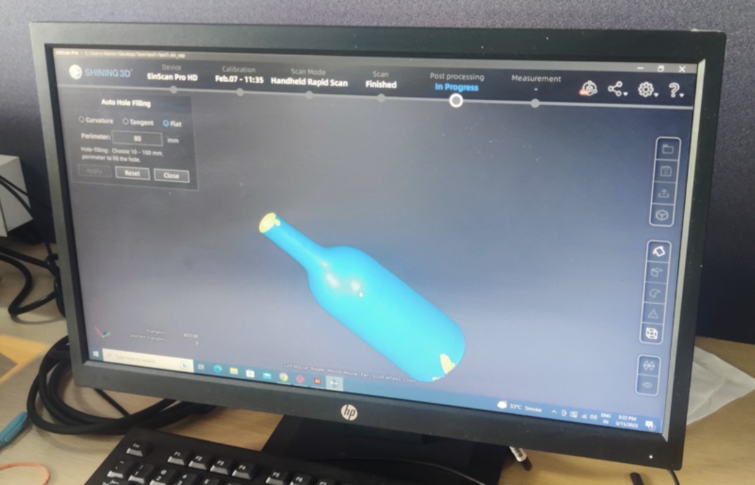
One such case was with the vase as shown below. We had a small inaccurately scanned semicircular cut at the tip of the vase. To fix that we tried Manual Hole filling setting, which should usually work but unfortunately since it was at the tip, the hollowness of the vase was also getting filled as shown.
Step 08: Exporting the file
Finally once everything is setup, we can just export the file in obj format. There are other supported formats also according to our instructor. The files were exported in STL format and can be downloaded from the links at the end of the page.
Group Assignment
Design rules of our 3D printer
So we tested our Fractalworks 3D printer and Jesal's own Prusa. We printed various test files given on Fabacademy page. The detailed photos are documented at Jesal's 3D printing weekWe tested for
1. Bridging
2. Unsupported angle (overhang)
3. Unsupported cantilever (overhang)
4. Printing widths
5. Clearances for in place printing
Download design files
Cable Manager zip fileHarappa Model Scan stl zip
Bottle scan stl zip
Holder design zip