16. Applications and implications

For this week we define our final project, the amplitude and the work plan that we will follow in this last stage.

  • For the project we must consider in the objectives:
  • 2D and 3D design
  • Additive and subtractive manufacturing processes
  • Design and production of electronics.
  • Interface and programming of microcontrollers
  • Systems integration and packaging.
  • concept

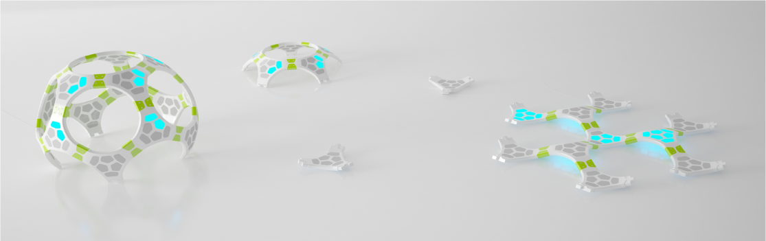
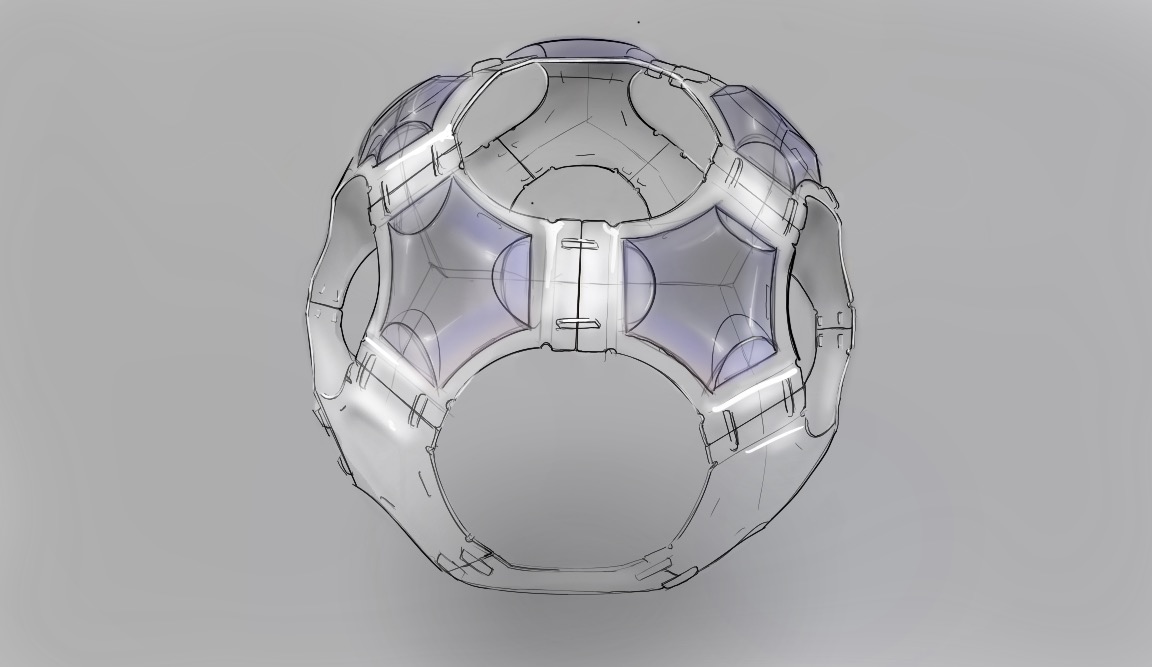
    The concept borns from a bubble, which is the interpretation of a safe place for many children with hypersensitivity. The idea is to use this bubble to interact with his users and break itself to create other spaces in order to encourage outside interaction safely.

    It is system, a multifunctional space to positively motivate interaction with the physical environment, in a child (10-12 years). with Autism (TEA).

    This is a modular system with multifunctional spaces in order to motivate positively physical interaction, it also improves interaction with the enviroment for one children and many other. Childrens practice their socialization abilities through a game with light patterns.

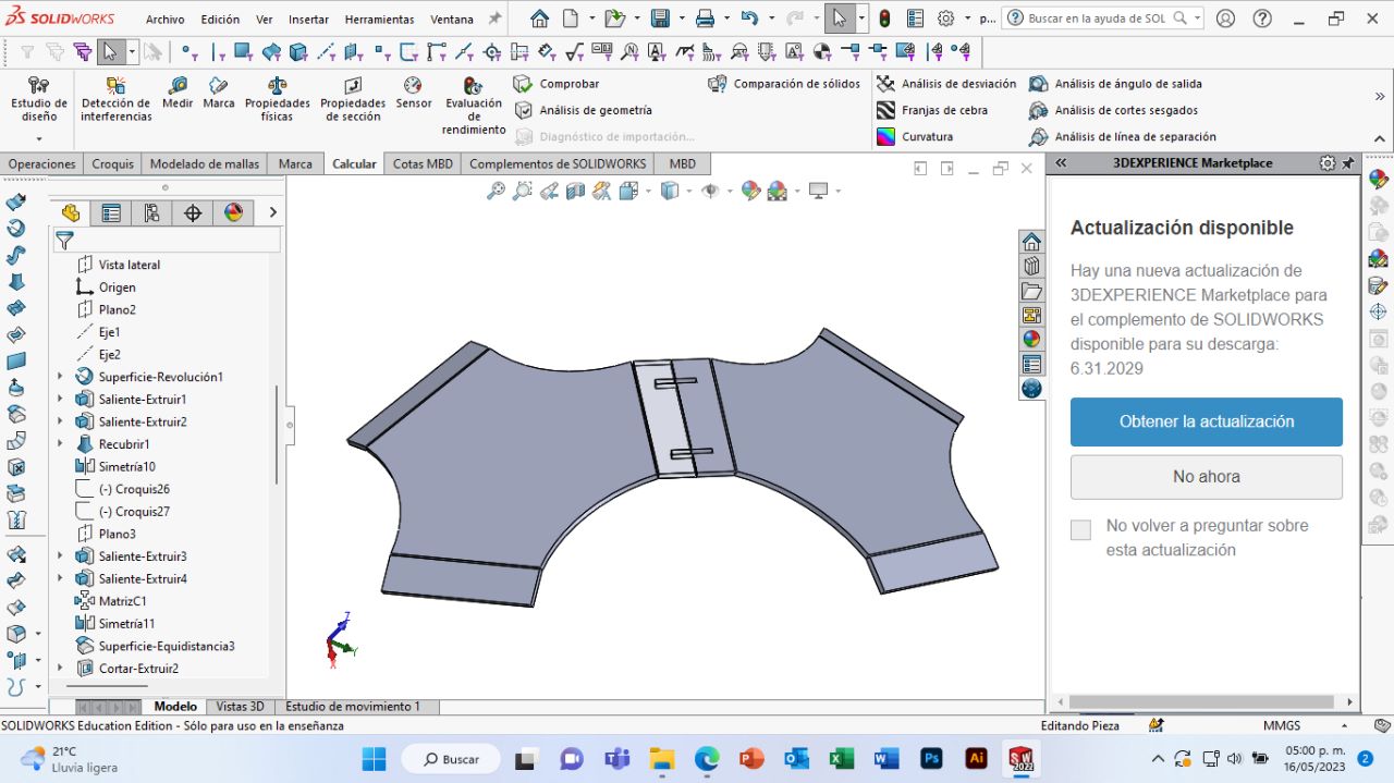
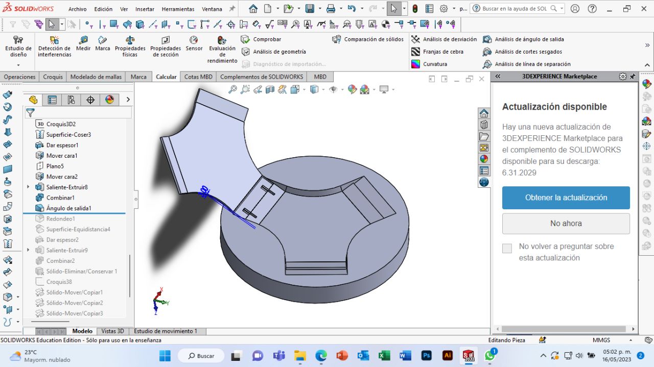
    This is a project of mine that I would like to resume to improve it, because I created this system as part of my final thesis project at UNAM, in the scope of production I was not able at that time to explore and closely test its versatility, which is why I am interested in retaking the system for my final project.

    img-fluid

    sketch

    For the design of my case it is important that it protects the PCB card, here I make a sckech in the SketchBook program to preview my idea.

    Final sketch

    First

    Throughout the weeks of the FabAcademy I was carrying out several projects related to digital manufacturing, these exercises could lead to the development of our final project. In my case, I directed most of my exercises, but it was in week 15 (Wildcaed week), when I began to manufacture my structure.

    First I designed my file in solid works to make a flat piece with the help of my project that I did in week 3 "Computer controlled cutting".

    Mold 1

    To carry out my thermoforming I needed a mold and a counter-mold, first I made my mold 1, I turned my solid piece into a flat surface, which I added a thickness of 20mm, to later substract that solid from a larger solid.

    Mold 2

    I did the same procedure as before, except that now the surface started from the other side of my module.

    Molds

    I saved my two molds in a single file as "stl" to later open it in the V Carve program.

    Autocad

    To check my cut file, I used the AutoCad program, I also made a design to engrave it and I arranged my pieces with the help of the "move" and "rotate" tools. Lastly I saved my file as AutoCadR12/LT2 DXF.

    Preparation of material for mold

    Before making the laser cut, I glued two 15mm MDF boards (it was waste from week 7). First I made some cuts and then glued it together and pressed my two boards together. Let the glue dry for 4 hours.

    Laser cut

    I did some tests to check the parameters for my cut, the images show the final parameters in which I cut my 3mm acrylic.

    V Carve

    I make the G code with the V Carve program, with the parameters of week 12, make two files, one for roughing and the other for finishing.

    router CNC

    I did the roughing and finishing of my mold with the security measures, in the process it took me around 5 hours.

    video

    >

    thermoformed

    To begin with, it is necessary to wear gloves as a safety measure, it is also important to accommodate the piece.

    video

    In this process, the acrylic piece is heated uniformly first, until it takes the shape of the mold for at least 40 seconds, then the counter-mold is placed for at least 5 min.

    cooling

    If the piece is warm can be cold with a pressured air.

    flat structure

    The module can be assembled in two different ways, one is flat, the circle is closed with 6 modules.

    sphere

    The other way of assembling is building a sphere, to close a circuit 5 modules are needed.

    PCB

    I used the schematic and the PCB board that I had designed and manufactured in my week 8, which I did before in my 6th week. This board is designed for a Xiao rp2040, with Hight Performance (Powered by Raspberry Pi 2040 chip, dual-core operating up to 133 MHz, equipped 264KB of SRAM, and 2MB of onboard flash memory), and Multiple Development Interfaces (2x buttons, 11x digital / 4x analog pins, 1x I2C interface, 1x UART port, 1x SPI port, and 1x SWD Bonding pad interface).

    For the generation of the G code, I use MODS that is quite accessible and easy to use, in my week 8 I explain how to use this tool. The Candle program is very intuitive and will help you make this cut on your CNC machine.

    I used the list that I generated in week 6, and I gathered the components to solder them one by one, I will leave the largest components at the end except the xiao to check their space on the pcb.

    Part Value Device Package Description
    C1 0.1UF C_CHIP-1206(3216-METRIC) CAPC3216X135 Capacitor - Generic
    C5 0.1UF C_CHIP-1206(3216-METRIC) CAPC3216X135 Capacitor - Generic
    D2 1655 1655 LED_1655 Ws2812b 5050 Rgb Led / Adafruit Industries 1.6 mm
    D3 1655 1655 LED_1655 Ws2812b 5050 Rgb Led / Adafruit Industries 1.6 mm
    D4 LED_RED CHIP-FLAT-G_1206 LEDC3216X75N_FLAT-G RED
    JP1 PINHD-1X3/90 PINHD-1X3/90 1X03/90 PIN HEADER
    JP2 PINHD-1X1 PINHD-1X1 1X01 PIN HEADER
    JP3 PINHD-1X4/90 PINHD-1X4/90 1X04/90 PIN HEADER
    JP4 PINHD-1X2/90 PINHD-1X2/90 1X02/90 PIN HEADER
    LS1 AI-1223-TWT-12V-R AI-1223-TWT-12V-R XDCR_AI-1223-TWT-12V-R BUZZER
    Q2 NPN NPN_SOT23-BEC SOT95P237X112-3N NPN - Generic TRANSISTOR
    R1 R-US_CHIP-1206(3216-METRIC) RESC3216X70 - Resistor Fixed - ANSI
    R2 1001 R-US_CHIP-1206(3216-METRIC) RESC3216X70 - Resistor Fixed - ANSI
    R3 3000 R-US_CHIP-1206(3216-METRIC) RESC3216X70 - Resistor Fixed - ANSI
    R4 000 R-US_CHIP-1206(3216-METRIC) RESC3216X70 - Resistor Fixed - ANSI
    R5 000 R-US_CHIP-1206(3216-METRIC) RESC3216X70 - Resistor Fixed - ANSI
    S1 B3U-3000P(M)-B B3U-X000B3U3000P(M)-B3000P(M)-B B3U-3000P(M)-B - Ultra-small Tactile Switch
    U2 XIAO-THRUHOLEHYBRID-SMT-THT XIAO-THRUHOLEHYBRID-SMT-THT XIAO-GENERIC-HYBRID-MODULE14P-2.54-21X17.8MM Seeed Studio XIAO Series Through-hole

    To start soldering, select my components and use a soldering station.

    The multimeter helped me verify that there were no crosses and the digital microscope helped me verify where I could have excess solder.

    It was easier for me to place the soldering first and then the components, these were very small and I did not have much experience, but I placed them calmly.

    It was quite difficult and I appreciate that my instructor told me to do the thick lines.

    Circuits

    When using my PCB layout, I only concentrated on the pins where I would have my programming, for my Neopixels I used Pin 2, for my buzzer Pin 4 and for my sensor Pin 28.

    Rate Sensor

    This sensor measures the heart rate, it is used to easily incorporate data into any project. The current consumption is low, being 4mA with a 5v supply. It is build with a emitting LED and also a intensity receiving sensor. The amount of light reflected by the finger bloodstream defines the output of the sensor, and it is possible to recover data from it.

    On the provider's website you can find tutorials on how to install the library and "examples" with different tasks to use in Arduino.

    Library

    For the Neopixels, I wanted to form a triangle with the lights, so I bought a NeoPixel strip from Adafruit, the triangle was made up of 4 neopixels per side, having a total of 12 neopixels. For these 12 neopixels, the following is taken into account: 20mA (consumption for each led) is multiplied by 3 (because they are the leds that each Neopixel, GRB contains), this is multiplied by the number of Neopixels and gives a total of 720 mA that my triangle of neopixels will consume, it is important to take it into account because my microcontroller has more, otherwise an external source must be used.

    First part

    This library have many "examples" for uses with the sensor. At this point i just used the "Getting Started Proyect" code. To experiment with it, i use an Arduino PCB and i put in place the indicated pines.

    Arduino PCB

    I follow the provider tutorials to make the first activation code from a blue led connected to an arduino plate.

    Xiao

    I started my programming on the Xiao microcontroller. Tools-> Board-> Boards Manager. Then i select the lastest version of "Raspberry Pi Pico/RP2040"; And finally i just needed to select the port. After this, i modified the code to play it with my PCB schematics.

    NeoPixels

    For the Neopixels, I wanted to form a triangle with the lights, so I bought a NeoPixel strip from Adafruit, the triangle was made up of 4 neopixels per side, having a total of 12 neopixels. For these 12 neopixels, the following is taken into account: 20mA (Consumption for each led) is multiplied by 3 (because they are the leds that each Neopixel, GRB) contains, this is multiplied by the number of Neopixels and gives a total of 720 that will consume my triangle of neopixels (I use a 500 Ohm resistor) is important to take into account because my microcontroller is larger, otherwise an external source must be used.

    Previously I had already installed the Adafruit library to use the neopixels, I started with a program where the leds were illuminated with the "rainbow" command, this assigns the present neopixels a different color from the chromatic circle.

    NeoPixels + Sensor

    At this point, I carried out multiple actions to reach the conclusion of continuing with the structure that I already had for my sensor to now integrate it with my Neopixels, taking into account the codes to show and turn off the neopixels.

    NeoPixels + Sensor + Buzzer

    For the Buzzer, I first had to convert a tune into the "tone" language that the Arduino has. First, put the music that interested me in the search engine and add the term “Jazz Chill”.

    Then I downloaded the melody I liked and on the “Midi to Arduinno” website and uploaded the melody to convert it to the tones I wanted.“Midi”.

    From the website I took the melodies that I liked the most and changed the frequency to make it sound better, to integrate them into the structure of my code in Arduinno.

    Arduino Code

    From the website I took the melodies that I liked the most and I played with the frequency in Tinkercad, then I passed the tones to the structure of my code in Arduino.

    Casing

    To protect my electrical components, I designed a casing in solid works, with the tools to "cover", "thicken", "fire", "round", "extrude" and "split". This case has the dimensions of my PCB that I had previously made.

    3D printing

    First I made 2 3D prints with the most visual part up, it took me 6 hours because of the support, because I wanted it to come out the same as the virtual one. I also printed two more with the open side up, it took less time but it didn't look as good as the first prints.

    After this I sanded my shells with water sandpaper and then painted them, first with a primer and then with a matt white spray paint.

    Components

    The module interacts with the user, by turning on the NeoPixels with an heart rate.

    Part Material Thickness Dimension Process
    Mold MDF 15mm 250X500mm CNC Router
    Base Acrylic 1.5mm 400x400mm Laser & Thermoformed
    Casing PLA 1.5mm 100x100mm 3D print
    PCB PCB 1.5mm 100x60mm CNC Router

    Who has done what beforehand?

    What exists on the market are sensory devices, what is most similar to my final project are colored toys where the child is given an instruction and he performs an effect. These toys improve coordination and laterality.

    Products Web side Description
    1 Auti It is a small robot that interacts with children and responds positively to the child's positive stimuli otherwise the robot withdraws.
    2 Leka Leka reacts to the child's movements while the child is playing with the robot. His face can change depending on the stimuli that the child needs at all times.
    3 "Build a Robot" This toy is made up of four different types of heads, each of which represents a different geometric shape (pyramid, sphere, cube and cylinder) and a face with the four basic emotions (joy, surprise, anger and sadness). With this game it is also intended to develop fine motor skills, since the little one must be able to correctly exchange the heads.

    How much will they cost?

    I suggest you make the mold with leftovers from other jobs, so you don't buy the MDF.

    When manufacturing the device the following cost must be taken into account:

    Part Material Cost min/cut Time Total
    Molds MDF Router 12.50 pesos/0.73$ 4 hours 175.2$
    Part Material Cost min/cut Total Material cost Total
    Laser Modules Router 6.50 pesos x 8 min/304$ Acrylic 500 pesos/ 29.12$ 333.12$
    Part Material Cost min/cut Time Total
    PCB CNC PCB Router 12.50 pesos/0.38$ 2.5 hours 57$
    Part Material Cost min/cut Time Total
    3D print Modules Router 1.20 pesos/0.070$ 6 hours 25.2$

    The total price of the elements we manufacture is: $590.57

    The parts that are on the market may be the ones that are best within your reach, I encourage you to go to my week 6, to check some elements such as resistance, capacitors and cables. Next I show you the most emblematic elements of my PCB that together have a cost of: $105.17, having a total cost of 695.74$.

    How will it be evaluated?

    There are different studies on the autism spectrum, one of them focuses on the heart rate response to strong stimuli such as sound or rough textures. These studies led me to think about using these same stimuli in a controlled way to generate a "safe" surprise so that children can improve their responses.

    The next step will be to do functional tests on my office colleagues, to find out if this device is optimal to continue with its development, it is a project that needs a lot of tests to be sure of its operation.

    Personally, I liked this project because it became my personal tool to de-stress in these weeks

    Contact me

    dimaricruzchavez Linkedin