7. Computer-controlled machining
This weeks topic was very exiting: we got to know the big CNC milling machine!
In group work we were to:
Indivual project was: Make (design+mill+assemble) something big.
Go to:
Group work
In group we learned about safety instructions, how to make toolpaths for the design and how to operate the machine. Then we got to see an example piece being milled, and we were to take measurements of it and compare them to the design of the piece.
We documented our local class and measurement results to the group work page which is on our Fablab Oulu pages. Check out our results!
Our instructor presented us the machine and we went through the following steps:
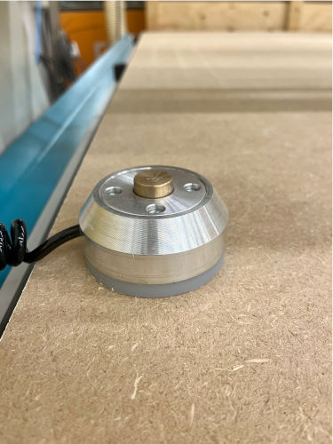
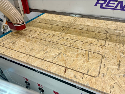
In the group work we used a 6mm, flat milling bit for wood. Our instructor had a piece of plywood that he wanted to cut 4 shapes of coat hangers from. In NC Studio we learned how to set the axels by moving the milling head buttons on the program and with hand wheel device. We set the origo with x and y axis, and used the mobile calibrating device to set the z also.
The file was loaded, vacuum and dust collector were on, so there was nothing else to do but to simulate the process in the program. Everything looked good in the simulation, so the milling could be started.
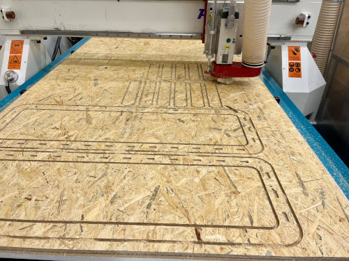
First the machine milled the pockets. After those it turned on to milling the outlines, and in that point the machine started to make this high pitched noise, almost like a whistle. Our instructor showed us that in that point you must change the spindle speed so that the sound goes down back to normal. You can try and find the optimal speed.
Everything went fine and the pieces were milled beautifully. We were also shown how to clean after the job is done, and for example how to use the sander machine. Then we were off to take the measurements of the cut pieces.
The measurements of the milled piece are close and error is very small in comparison with the design file. We had contours in outlines of the piece and pockets in the engraved letter A. Everything worked out really well and very close to the original measurements.
3D model
Planning
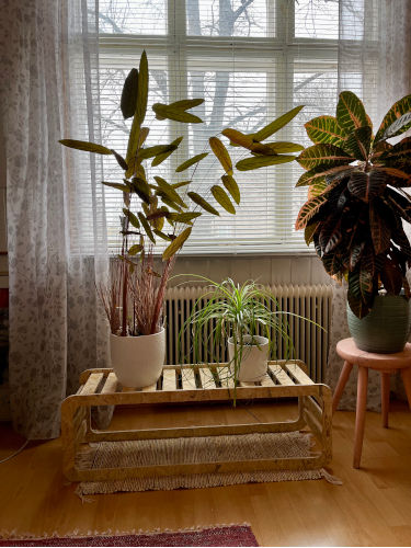
I was eager to start my own working. I had some problems on deciding what to do, because my home is really small and the scale of our design had to be at least one meter on one dimension. I thought some kind on small table could be alright, and I could use it to put some of my plants on it. I'm not much of a designer, so I searched what was done in previous years on Fab Academy. I did find a table that I liked to have as a starting point! It was from year 2017 and the student was May El-Dardiry. Here is the assignment page.
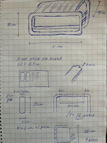
I wanted my table to be 1 meter long, and about 30 cm high and wide. Also I didn't want any boards on the bottom so that it is easier to clean under it. I thought I must add boards to the side thought, to make the system more stable. I started again by drawing and planning on my notebook. I wanted 5 cm wide boards with 2 cm between them. I wanted the boards placed in a certain way and calculated to know the measurements.
Designing
Off I went to Fusion360! I'm really starting to like this program, how ever much I still have problems while using it. But it always gets the thing done, all problems so far have been user oriented.
Since I have used the tools before, I'll just explain about the basic idea.
One new thing for me was the mirroring of the component and then rotating it. It was easy: choose the component/body and go to Create -> Mirror. You choose the object type, select the object and then choose the plane for the task.
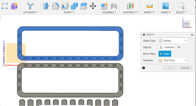
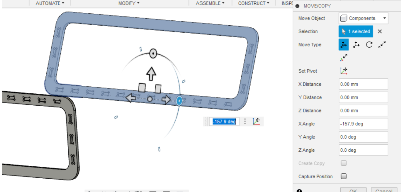
When it is done, the mirrored object is behind the original one. You have to move it and then rotate it. Choose your new body, right-click and choose copy/move. Set pivoting point and rotate in this case 180 degrees.
Here are my parametres. At the beginning I added also Kerf in case I would've needed to use one. Also at first I designed a dog bone -feature to the slots, and used the diameter of the milling bit as a parametre.
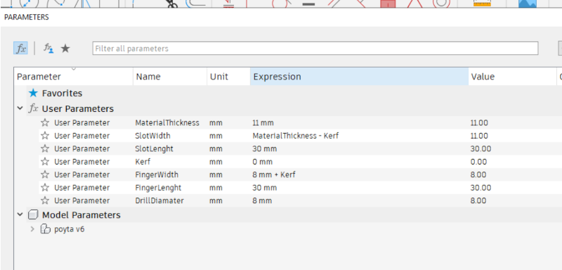
So about the dog bones. One of my instructors said that while the milling bit cannot make sharp conrners to the pockets, it would be good to make dog bones in the slots of my design. I did them by adding circles in the each corner. If they had made in to the final design, they would've needed to be a bit more bigger than the milling bit so in my case 8.1 mm.
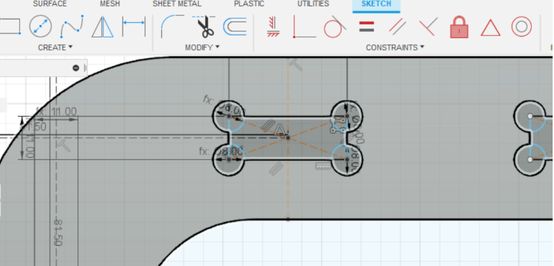
But then..One instructor told me that if I do the dog bones, the pieces are much easier to get together with the finger snap -joint, but it might not look so good. Especially in my design, because the table will come to use and the round holes of the dog bones would be seen on the ready design. At this point I decided to go with taking them off, and doing some extra work after the milling.
Well..more on that later. Maybe not the best of my ideas.
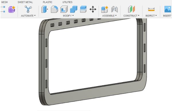
But the design was ready! I was happy with it, and then it was just about making the toolpaths.
Setting up toolpaths
For the milling I needed to make an NC file in Fusion. An NC file is a data file that contains numerical control instructions for directing a CNC machine tool, such as a router or drill. It tells the machine what lines to follow with a particular diameter cutting tool, how fast to cut, how deep to cut on each pass, how fast the spindle is turning and so on.
When 3D model was ready in Fusion, I went to Manufacture workspace.
Setup
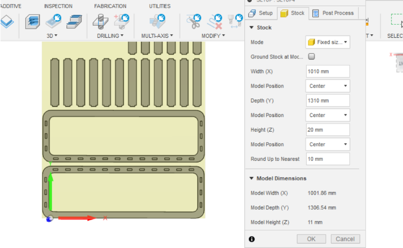
I started with the setup in Setup -> New setup. In the second tab there is Stock in which I checked for the dimensions of the model (width, depth and height). In my case it could be seen that the coordinate system was not alright, and the y and the z values should have been the other way around.
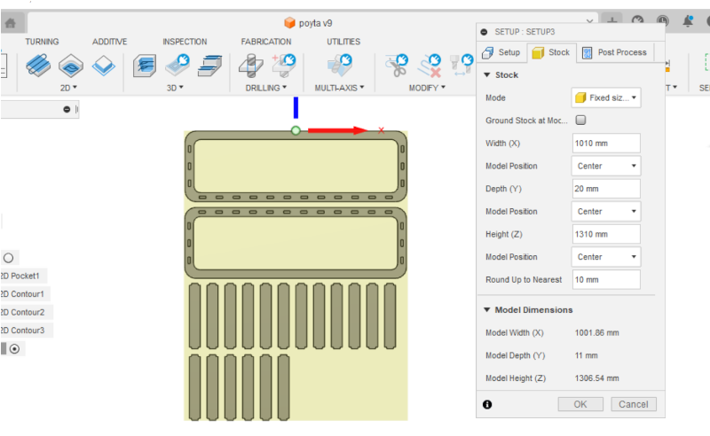
I went on to change the coordinates to as they should be. For Orientation I chose 'Select x and y coordinates'. Then I selected both x and y axis by clicking any part of the design laid out in the correct axis. The x axis I also had to flip. The origin point I selected from the model to be the bottom left corner.
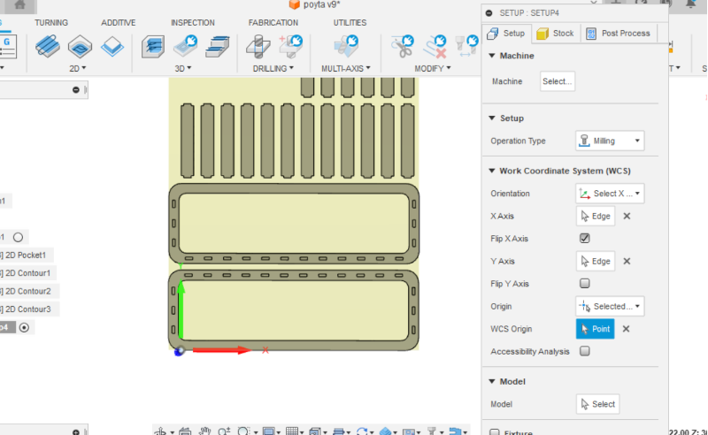
Now when I checked again, the dimensions were right. The z axis (model height) represents the thickness of the material. I was ready with setup and pressed ok.
2D pocket
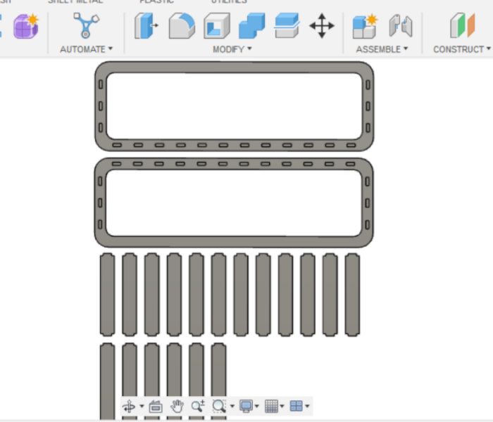
Now I was to do the pockets in 2D -> 2D Pockets. These are the slots in my design; they are 8 mm deep and do not go through the material.
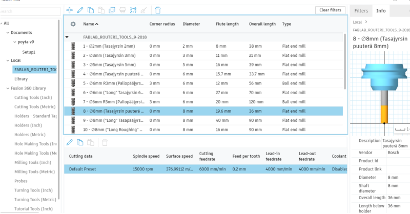
The very first thing was to choose the tool I'm using in the milling. In this point I had to import the Fab library to get the listing of proper tools.
In Tool tab I clicked Select and opened the library. Under Local folder I clicked Import library and chose the one we were assigned in the fablab wiki. In that library it was easy to find the right tool which was in my case the 8 mm flat end mill for wood.
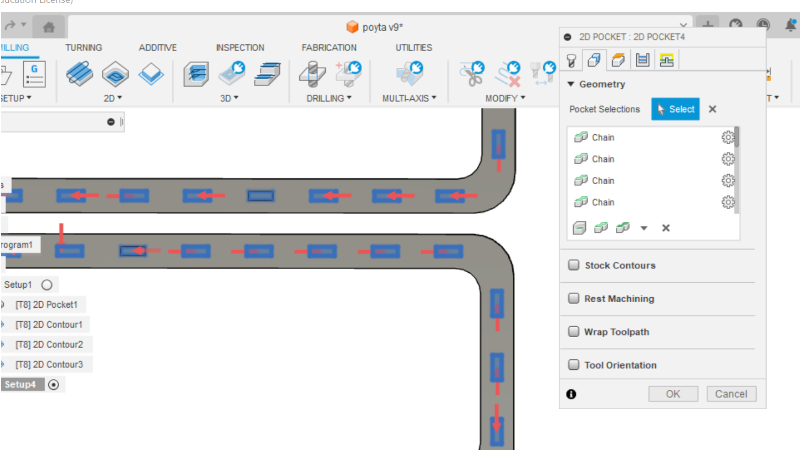
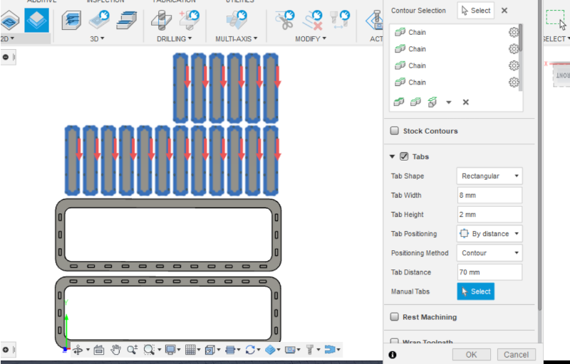
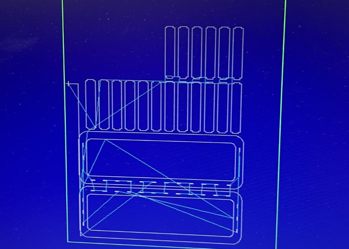
In Geometry tab and started selecting all the pockets in my design (2 x 18).
In Heights tab I changed the 'Top Height' to 'Model top'. For the 'Bottom height' I had to choose the bottom of my pocket by 'From selection' -> choosing the correct face.
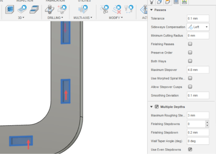
In Passes tab I chose Multiple Depths and the Maximum roughing stepdown of 3 mm (and use even stepdowns.)
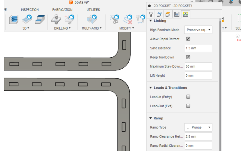
2D contour
The same steps had to be done also to mark the outlines of the model to be cut. In my case I created 3 different contours; the inside and the outside outline of the frame, and the outlines of the boards.
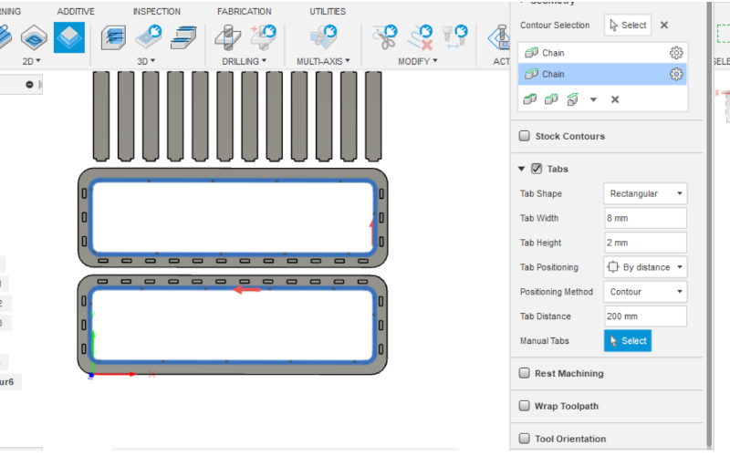
Same operations were done to outside outline and the outline of the boards. In the boards I changed the tab distance to 70 mm, since the parts are smaller.
Simulate and saving the file
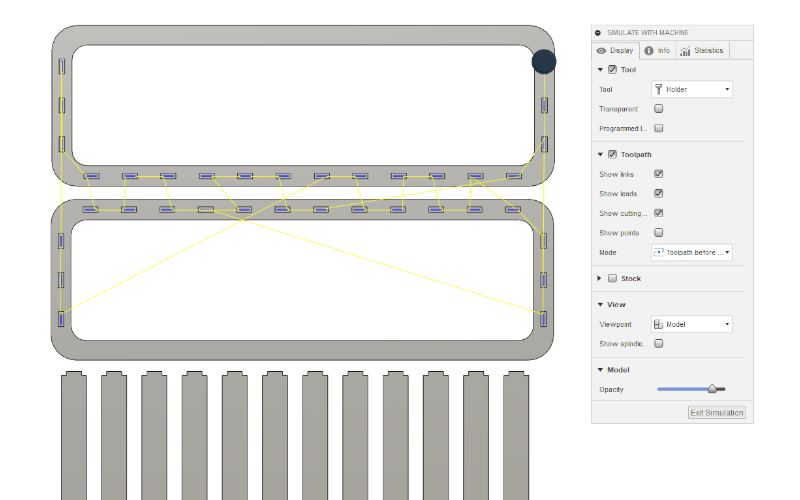
When the 2D pockets and 2D contour were made, I chose my setup and pressed Action -> Simulate. The program showed me piece by piece how the milling would go.
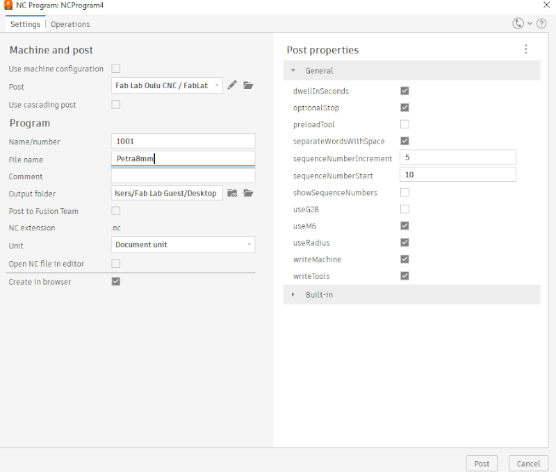
Everything looked fine to me, so I went to set the path to postprocess file and save the .nc file I needed to the CNC machine. We were recommended to save our file in the way that we recognice it and add the tool size so we won't forget it.
Machining
Off I went to the machine! This was very exiting.
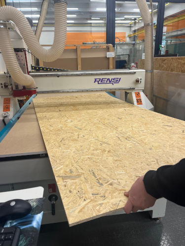
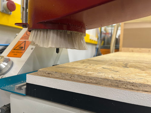
First I grabbed the OSB board and I had help to get it to the table. The material is light, but such a big board of it is not easy to move around. I measured the board thickness previously, and it varied a bit along the board. That's why it was interesting to see how would it affect the milling outcome.
Setting up
Then I opened the NC Studio, and opened my nc file. It looked something like this.
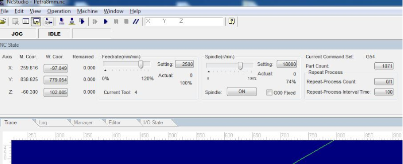
First thing I started with was setting the axels and the origo. I moved around the axels first with the program and jog mode, in which the panel looks like this. When I pressed also the ctrl -button, the milling head moved more rapidly.
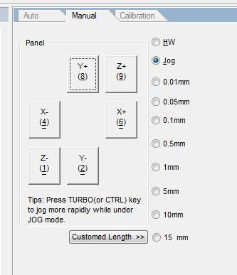
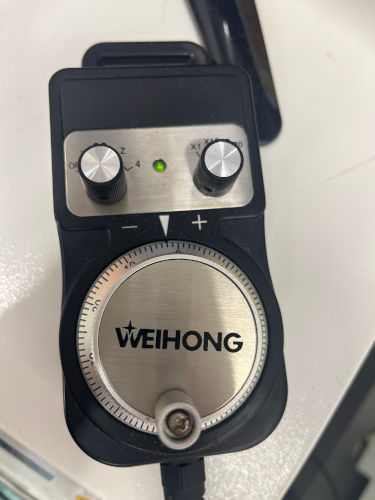
Then I tried also the hand wheel. I chose HW from the program panel. From the handwheel I chose the axel I wanted to move, and then just turned the wheel by hand. It was very good when I was closer to the corner of the board where I wanted to set my origo, because with the handwheel the device moves very carefully.
I found a good spot for my origo, which was near the bottom left corner of the board (and my design). The origo was set in the NC Studio control panel by pressing 'W Coordinate' buttons for x and y axis on the top left corner.
I still had to set the z axis correctly and I used a mobile calibrator to do that. It is stored on the side of the CNC machine. When you calibrate, you put it to the milling table. You move the milling head right above it, then move it down close to it. You can hold on to the device and then press yes for calibration on the program. The milling head goes down and touches the calibration device a couple of times. When it is ready, it moves back up and stops. The calibration is then ready!
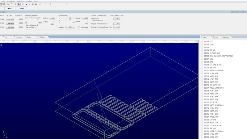
Now I could run the simulation from the program. It is done with the left play button on the panel. Everything looked good!
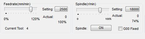
As I was set, the only thing left was to set the speeds. Here are my numbers for Feedrate and Spindle.
The milling
I double checked that the dust collection and the vacuum pumps were on, and no one was near the machine. Then I could press the play button!
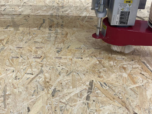
The whole process of milling went fine, and it took about 30 minutes to finish. It was very relaxing to see the machine operating, especially since there were no problems!
When it was done, I removed the material and cleaned the area.
The results
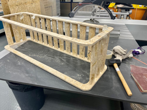
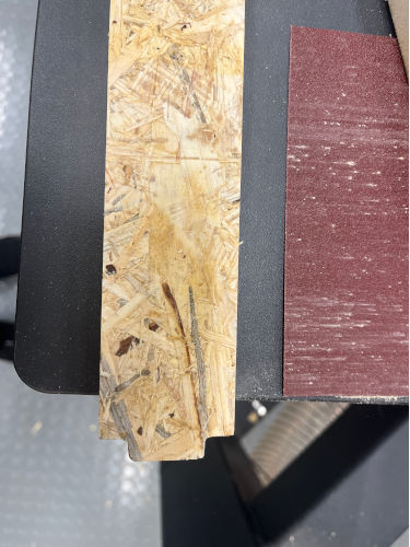
I noticed that besides the tabs, there was quite a lot of material still left on the outlines of my piece. The outlines were seen through from the other side of the board, but they needed to be cut out. I first made small holes with a knife, and then sawed along the outlines. It turned out to be quite hard, because the piece was big and I couldn't attach it to anywhere properly. Some of the outlines I cleared with the knife and a hammer.
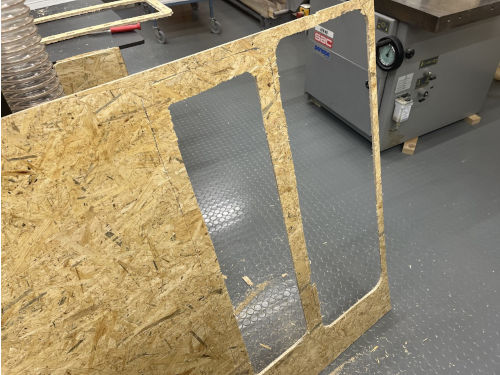
Eventually I did get all the pieces off but it was quite the effort.
I don't know why the outlines were not cut fully. My measurements were ok and so were the set toolpaths. I discussed this later with my studying friends, and one thing we came up with was that maybe it had something to do with the calibration of the z-axis. One instructor told me that it might be sometimes better to calibrate by hand. But it didn't explain the problem, since I had seen success in other peoples work when using the mobile calibrator.
One thing was that I don't remember if the suction pumps were on when I was using the mobile calibrator. If they were not, that could explain this oddness. Since the pumps suck down also the whole milling table (layer) beneath the material, it could've been a bit loose and therefore the calibration failed.
Anyway, a lot of sanding needed to be done. I used a machine for that and sanded the outlines of the pieces.
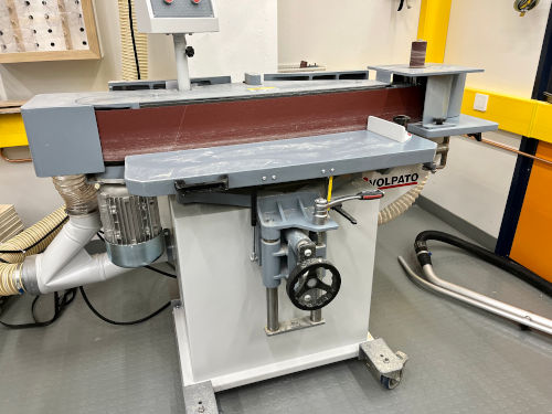
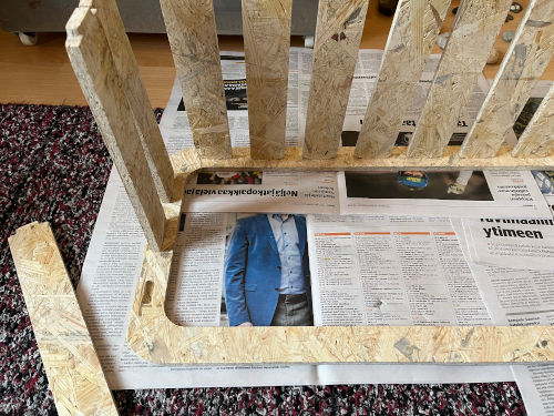
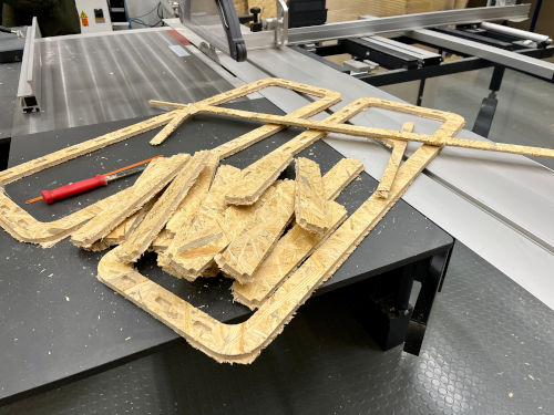
Now I get to the part of the not having dog bones in the pockets. Because the milling head does round traces on the pockets, my finger snap joints were now not entirely compatible. So I had to sand off the finger parts to fit the pockets. This I tried to do with the sander machine and by hand. I had 18 boards and 36 fingers needed sanding..so that was nice. With my lack of experience and some frustration my sanding job wasn't that good. I did get the fingers to finally snap to the slots, but it took a lot of effort and the end results were not 100% similar on each board. Not even 90%.
After all this, and seeing the end result, I now think that the dog bones would've been alright. Yes you can see them in the product, but I don't think it actually would bother me. Maybe. Still I am happy also with what I did, although it took a lot of time.
I like my table very much! I also started to put some filler on it and I will paint it later on.