19. Project development
The assignment for the week:
The Final Project
My Final Project is a reaction time board. The background of the idea and making of the project you can read from my Final Project page.
The last 2 weeks before presenting the final project are quite hectic. I had made a few plans earlier about the board, the casings and the overall functioning of the game. But now I needed to get into action.
The second to last week
I had few aims at this week.
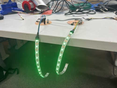
I design the node pcb in Kicad, and produce it with precise milling machine LPKF. Then I solder on the components. It has a microcontroller ATtiny1614, LED strip, distance sensor, connective pinheaders, condensators and resistors.
I test the node with a simple program that just lights up the LEDs and takes a sensor reading.
*Note: I wrote the program first, which was easy because I have previously used the sensor and a LED. But I had to learn how to program the ATtiny. I got some instructions on how to do that from my instructor. I use an UPDI programmer they had ready at Fablab Oulu. On Arduino I use the compile with programmer-option.
I make a skecth about how I want the reaction time board to function. I need to make one code for the main board, and one for the nodes. I start with just writing down the things that need to be there. I check Networking week on how to use the serial communication.
Start preparing the LED strips and cables for testing serial communication. Parts needs to be ready when I have the nodes ready next week.
The last week
In the last week before presenting the project I will do all the things mentioned below (from Thursday to next weeks Wednesday, when the presentation is).
The electronics
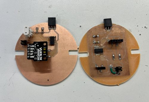
As the node pcb worked, I knew my components and idea worked, but I needed to make the design a bit better. For example, the sensor was not in the middle. I made a new design and tested it, and was happy with it. I started making more of these pcb's this week. I have made 3 so far. In total I will make 6. I will start on the weekend and continue in the beginning of the week if necessary.
*Note: I got them done on the weekend. I lost one of them later in an accident, so I made one more on Tuesday.
The casing
I finished the design for the casing. I decided to do the casing from see trought filament. One test piece was 3D printed on Friday. I made slight modifications to it, and it will be printed few more times this weekend.
The board
I need to make the board. If I don't have enough time to mill it with CNC, I will cut it by laser cutting a test piece of MDF that I can use in the presentation. This I will probably do on Monday. I will also paint it.
The programming
The programming will go forward step by step, every day. I am very fortunate to get some help from good hearted instructor. First step was to make a sketch for the nodes (LED rings). I used my knowledge from embedded programming week, input device and networking week for it. When the node address is sent in serial communication, the node lights up the LEDs and the sensor starts working. To do: how to send a message back to the main pcb?
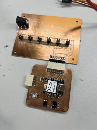
I have also started the programming for the main pcb. I will use the board I have made earlier. I started with sending the node numbers one by one, and seeing if the nodes answer. It has taken a ton of trials and errors, but it finally worked. In one point I sadly had crossed something on the serial bus, because I torched one ATtiny on my node. I replaced with a new one and gladly it is working again. I also progressed to use messaging a random node number. I also got the OLED display connected. To do: Add button, get the message from nodes. This all will be done on Monday-Tuesday.
*Note: Programming happened on Monday, Tuesday and Wednesday. What did work: The start message in OLED. When button is pressed, the game begins. The program sends information to the nodes, and when they get an input of their network address, they activate. The LEDs are green at the beginning, and in 2 seconds they go yellow to indicate time soon ending. When the sensor senses hand in under 4 cm, the node will deactivate and the next node fires up randomly. Also the node number is shown in the OLED. In the end, result screen shows in OLED.
Pcb for serial bus and power
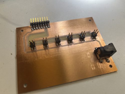
I have to design and make a pcb that I can connect my power supple to, and send my serial communication. This board is then connected to the main pcb. I will design the board on Monday and also make it.
*Note: I did this on Monday. Inspite of designing it carefully and approving it with someone, I managed to not connect the power and ground properly to power socket. Therefore, when I tested it I fried one node. I found out later it has minus 5 V in it. I have no time to fix this, so in the presentation I will just use USB power straight to the main pcb. It is no problem, and I'm in a hurry. I did learn anyhow a valuable lesson.
The finishing
I also need to make a box or such to get the main pbc, wires, button and OLED in to. This I do on Monday-Tuesday.
The documenting
While doing all this, I also need to do documenting on my final project page, and make the slide and the video. I will make it as I go. The slide I will do on the weekend and finish when I have the project ready. The video of course can only be finished when I have something to show on it (even a peak of the final design).
*Note: I did the video on the last possible time on Wednesday after I got everything working. Gladly I had thought about it, so I knew exactly what to do and what to put there. I did the video with iMovie iPhone app, and compressed it with ffMpeg.
Learning experience
The last couple of weeks were super hectic and very stressful. I was lucky to get through them. I know I understood the whole consept and the demands of the project just lately, and therefore I couldn't start the fabrication earlier. One of the reasons for this is that it takes a lot to keep up with the assignment weeks and their documentation. Regardless of that, I should've tried to do something earlier. But it was difficult, since so many things of the final project needed to be fabricated at the same time and were dependent of each other.
I learned that it is fun to design and make pcb's! I have befriended KiCad and LPKF and understand now a lot more of electronics design. In the process I also learned how to take different measurements with the multimeter.
Something that is still super hard for me is the programming. I am starting to understand the basics and the structure of the code. I know where to search information. But it takes a lot of time for me. I hope to learn more about programming, and possible also micropython. Many thanks to my instructor Gleb who helped me on the way.
In the overall experience, I would say the most important fact learned is that we can make almost anything. It can take a lot of time and effort, and multiple failures. But the important thing is to get up and try again. Resilience. And same minded friends are a help and a motivation! It has also felt so nice when I myself have had the chance to help others. So basically problems are nice, you get to learn a lot and then share your knowledge!