5. 3D scanning and printing
This week was all about 3D printing and scanning. As a group, we first learned about 3D printing and tested the design rules for the printers so that we would understand what to take into account when 3D printing.
We documented our work to the group work page which is on our Fablab Oulu pages. Check out our results!
We used 4 different 3D printers and printed a few test models. First test model had already been printed by our instructor, so that we had sufficient time to print the ones that were left. We wrote down the print settings and inspected the results at the end of the day (for example overhang, wall thickness, clearance..). Our findings are at our groupwork page.
So I learned what differences there might be with the same test piece printed with different 3D printers. I learned which printer does the best quality, about the time that it takes to print, the processes and also about possible problems. I think the best quality we got from Formlabs Form3 and resin, but that took awhile. You first print, then you give the print a bath and then put it to oven. But if you have time, this is the machine to go with. I also learned about the process, it was fun to watch how the printing with resin worked. For example, the piece was printed tilted so that it wouldn't create suction to the bottom of the pool. One other printer that made an impression to me with the quality, was Raise3D Pro2 that worked with ABS.
Some problems we had were with Ender, because our print didn't first stick to the glass table. We were guided either to move the printing surface away from the middle table, or try with a different machine. One user had good experiences on a differend Ender, so we tried that an succeeded. I guess the tables wear and bent in use.
There were a lot of problems in the clearance tests. This was interesting since I had to use clearance in my own design later on. Because of printing taking a lot of time, we split our group work printing between two groups. The first parts were looked upon together. My group printed the Test 2 parts, which focused on wall thickness. The other group printed the clearance and overhang pieces. They had some trouble in printing because they were really new to it. Therefore when we were looking at the results, we figured that some of their settings might have also affected the printing outcomes.
Because of this, I wanted to try my luck with clearance number that was documented to be a success in the previous years' students work. Also I had really liked this Raise3D printing machine and somehow I trusted it's capabilities. In the end, I set the clearance to 0,2 mm in my own work and it worked good! You can check the results from below documenting.
Individual assignments were:Go to:
Design a 3D object
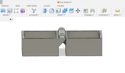
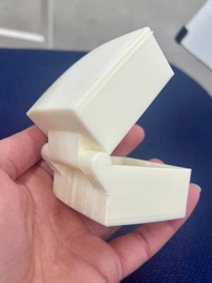
We were to design an object that could not be made subtractively. I again wanted to make something I could in theory also use if it succeeded. I found out that in previous years someone had made a box with a hinge, and I thought this I could try. It cannot be made for example by milling because of the hinge. It consist three parts: a pin, 2 ancors and a knuckle. As the pin is hidden inside solid material, it cannot be made subtractively.
So again I found myself opening up Fusion360. So far I've done enormous effort by just trying to figure out the program by trial and error. Not to exhaust myself, this time I searched for a video tutorial. I saw that one of the boxes made in previous year the snap joint didn't work in the best possible way. So I looked for a different kind of box. I found one that seemed good to me in this point.I used the video of 3D Hobbee.
I was instantly happy about the quality and straight forwardness of the video. As I glanced throught it, I noticed that the thing that was new to me was the making of the hinge and the specific snap joint. Therefore I emphasize making those in this documentation.
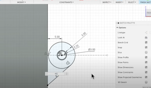
After drawing the rectangle, I started to design the hinge. I added three concentric circles to represent the pin and the knuckle and input their sizes. The area left between the two smallest circles is the clearance of the pin which in this case was set to 0.2 mm.
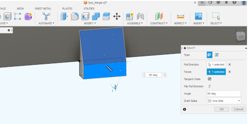
Then I started making the hinge. After creating the circles, I joined together with a line the box and the knuckle, making it 45 degrees from the edge of the box to the tangent point of the knuckle.
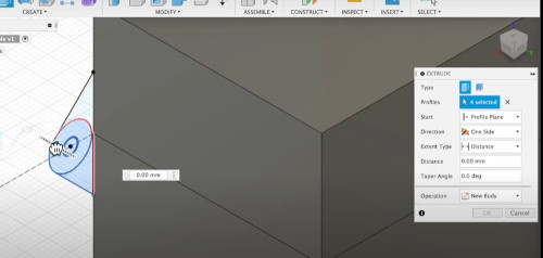
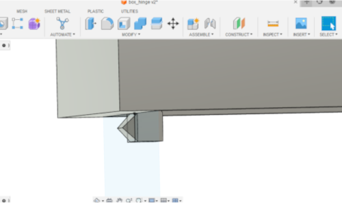
At this point I created a midplane (Construct -> Midplane) to have the box cut in top and bottom parts (Modify -> Split body). Now I was ready to start extruding to make the pins, the wings and the knuckle. I chose all the sketch features needed and also changed the operation to 'Join'. Then I just extruded to minus 9.5 mm.
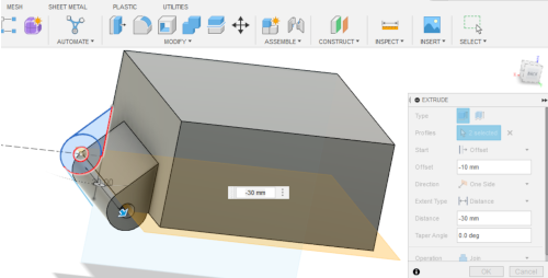
The other wing was made similarly. Now I had to create the knuckle for the top part of the box. I allowed the visibility of the top part and hid the bottom part. I chose the upper wing and the middle circle and extruded. Start was set to offset of minus 10, so that it begins from the right place. Now after I turned on also the bottom part, I had my hinge ready!
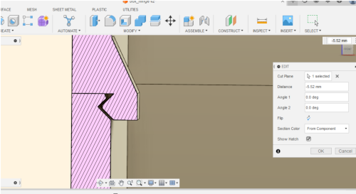
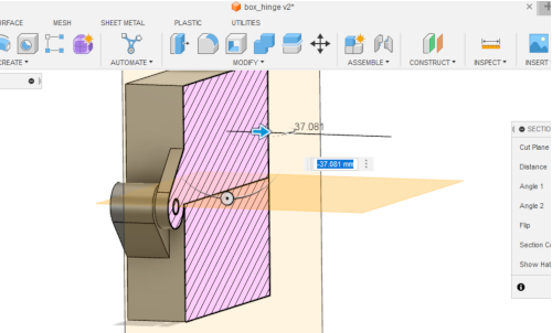
For inspecting I used the section analysis tool. After that I found myself with the trickiest part of the project; to design to snap joint to the front of the box. I used the section analysis tool just to see the front part of the box. I created a sketch to the bottom part and specifically to inside phase. I added a rectangle. I used the midpoint constraint to center the piece. I extruded into the body with a taper angle of 45 degrees and added a chamfer.
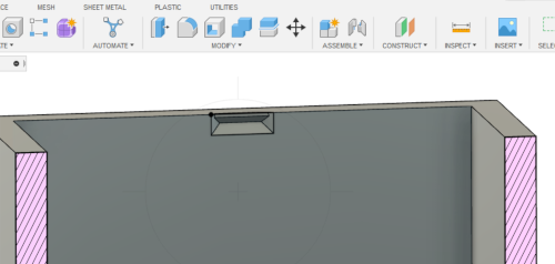
There was still to do the catch point on the top of the box. I extruded once again the rectangle from the behind view of the box. To object I chose the front face of the snap fit part, dragged it to 2 mm and entered a taper angle of negative 45.
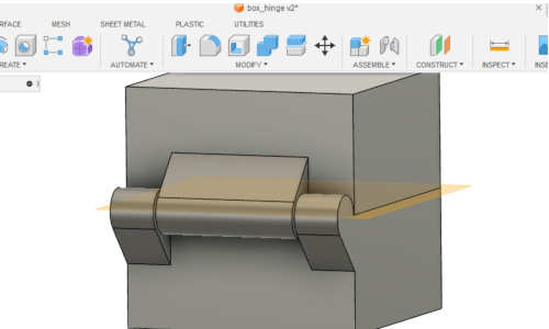
I used the section analysis tool to verify the parts being as they should.
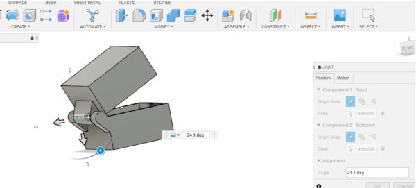
Now I animated the rotation of the lid. I made new components from the top and the bottom part of the box. In Assemble -> Joint I selected the top parts' centre of the knuckle. In the bottom part I selected the centre of the pin. Now I could grab the rotation handle to rotate the top part of the box.
3D print the object
I was so excited about this part of the assigment. I hoped the box was designed well and and now it was all about choosing good specifications for printing.
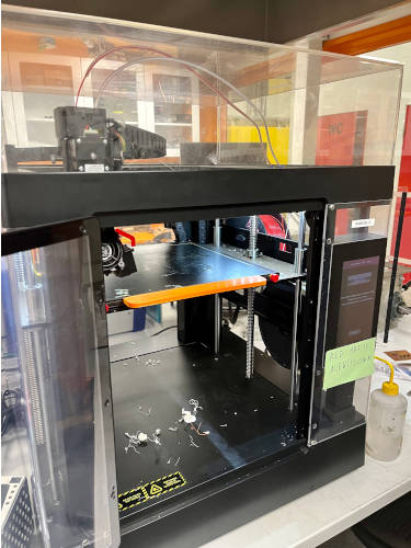
I chose to print with Raise 3DPro 2. It is a dual extruder 3D printer with high-resolution for manufacturing and rapid-prototyping projects of varying sizes. It has a metal build plate for even heat distribution, a 7-inch touch screen for efficient monitoring of the 3D printing process, and a HEPA air filter. Pro2 Series can pair with: ideaMaker, a 3D slicer software and RaiseCloud, a cloud-based 3D printing management platform. (Source Raise3D webpage)
As printing filament I used white ABS. Diamaeter was 1.75mm +-0.05 mm. ABS is a popular material for 3D printing due to its light weight, resistance to impact and tolerance to different temperatures in the finished product (between -20°C and 80°C). The Run Temperature of the ABS that I used is 210°C- 270°C & Bed Temperature is 100°C-120°C. It is opaque and offers smooth and shiny surfaces. The use of a heating plate (between 80 and 130°C) is mandatory: it is a plastic that shrinks on contact with air, causing the part to shrink (or warp) and thus detaching itself from the plate.
To support and raft I used HIPS filament. It combines the hardness of polystyrene with the elasticity of rubber to produce a high impact thermoplastic that is tough and strong without being brittle. Bed temperature needs to be 100-120 degrees.
Once the printing is complete and the object has cooled, you can remove the HIPS by submerging the object in Limonene for 24 hours. It will dissolve the HIPS leaving you with a print job that has clean, crisp angles, corners and overhangs. There is no need for knives..except when you are in a hurry like I was! More on that later.
Before slicing the design, I made sure everything was ready for printing. The printer had been used before me, and I had to both clean the surface and change the material. In that I had help from an instructor. The ABS filament was entered to a plastic tube from the side of the machine. We put it down to the printing head towards the nozzle.
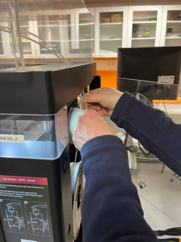
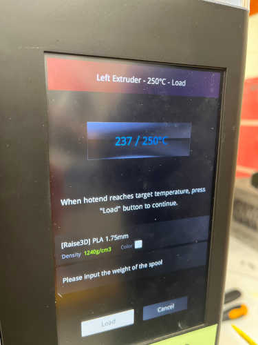
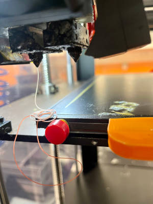
The machine gave us good insructions. It heated up the nozzle, and when it was ready we just pressed 'load' and the nozzle passed on some previous material (red) and then successfully the new one.
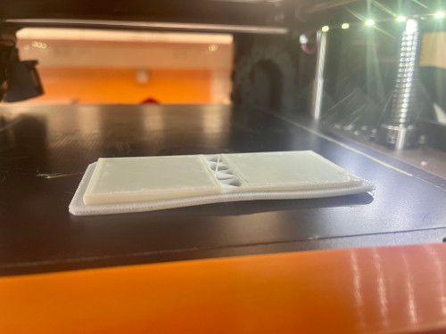
Then I wiped the table clean with isopropanol and paper. As you will see later on, my print actually warped a bit beginning from the raft. The raft did not stick fully on the bed. At the beginning I was instructed to print on the corner of the bed, because sometimes it can stick better there because it's less used. Also I found out there is a cleaning cloth used for cleaning the beds, so next time I print I will maybe try the mid bed and also clean it even more better with the cloth.
But everything seemed ready now for the printing. Next thing was to create a toolpath for the printer with slicing. I used IdeaMaker. At this point I thought it would be best to go with a well known and proven to be good template, made by some instructors. It had the layer height of 0.16 mm which I already had been contemplating about. Infill density I did change, because I thought it isn't so important in this design and lowering it saved some time. Actually, even after this, I was still stuck with over 5 hours estimate.
So:
As I am new to this, I asked for advice about the supports. The instructor who was there recommended that I could use the support. I thought it might affect the stability when printing the hinge part. Later on my global evaluator noted me that because my overhang was only 45 degrees, it should've printed just fine without it. Than we saw also in the group work. I agree now when I have learned more about printing. Supports can mar prints, print times, and material consumption so there's no need to have them in just in case -situations.
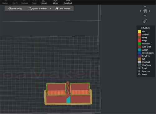
After checking the settings, I pressed Start slicing. When it was ready, it was fun to see the review it made of the structure of the box. Then nothing else was left to do but to press upload to printer!
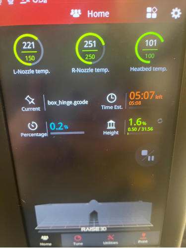
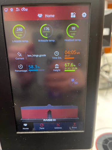
I went on to the machine, and my work was shown on the work list. I just pressed ok, and it started to heat the bed. That actually took awhile, maybe something like 30 minutes! The estimate for the print was about 5 hours at this point.
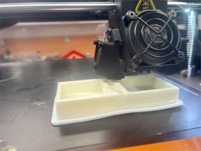
Finally after heating up, the printer started by making the raft. It was an exciting moment; will it stick and will everything start off good?
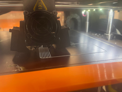
It did stick and everything was going smoothly. By the time it was doing the first supports, I noticed the raft was not sticking anymore in the corner. It wasn't bad yet. But when the lids were about ready, the warping was clear to my eyes. I still wanted to go through with the print because this is a learning experiment and it was intriguing to see how this would affect the final result.
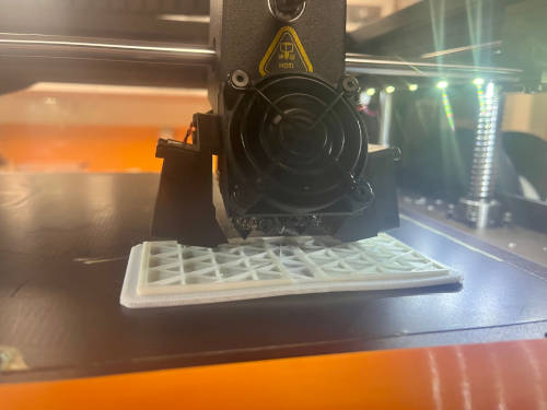
I visited the print every now and then, and everything was peachy besides the warping. It was very nice to see it coming along. The hinge part naturally was interesting, I had high hopes that it would turn out well.
In some point I noticed the estimated 5 hours was coming to an end, but the print wasn't. There was almost 40% left of the work, said the screen. It did show me additional time of 4 hours. I don't know why this was the case. It seemed to me that the nozzles were warming themselves up all the time during the work, meaning they took some small breaks all the time. I asked about it, and was told that it has something to do with maintaining good but not too high tempreatures while printing. Anyway, I patiently waited and hoped it will finish at some point.
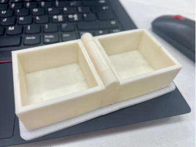
It did finish! And it didn't take the additional 4 hours, but something like 2. I was so excited I almost burned my hands on the bed. But the print was very easy to take out, since it is a character of the HIPS that made the raft. The print was also easily taken off from the raft.
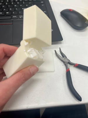
Since I could not wait (because of the schedule and especially my impatiency!) I did not try to solve the extra material, but scraped it off with hands and then with a knife.
I was very happy with the result! Now I have a functioning and a strong box to keep my microcontrollers in. This most definitely gives me extra boost and interest to print more stuff. Wait..was this a trap??
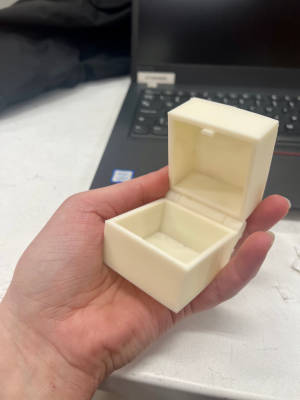
Here is a video of the box in use. I have stored some small items in it, for example the MCUs. The box has been in use now for weeks and is still functioning flawlessly.
3D scanning an object
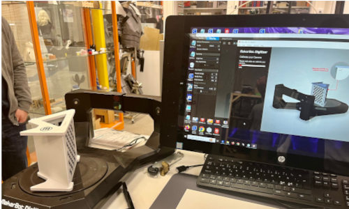
The scanning part was 100% new to me. I checked up some options we were offered or recommended, and ended up with trying the MakerBot Digitizer. It generates a 3D model by spinning the object in a turning table slowly while taking pictures of it. The output is a standard 3D model file format (STL) that can be modified and improved in third-party 3D modeling programs, like Autodesk’s free software MeshMixer.
To make sure to get the best possible outcome, I calibrated the devide first. I placed the checkerboard calibration tool in the center of the turntable. There were 3 steps to calibrate; A-side up, B-side up and C-side up. Each time the turntable spins around scanning the calibration device. This took maybe 10-15 minutes at most.
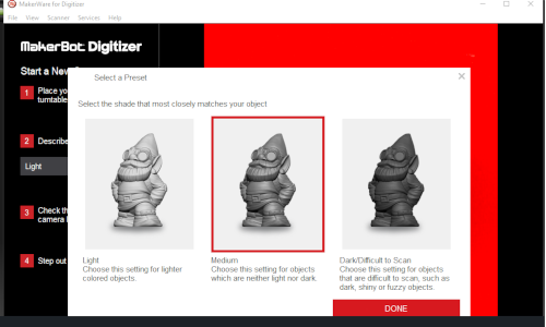
I was ready to start a new scan. I placed my object in the middle of the platform. I had chosen a lumbar vertebrae of a capricorn I had. Since it wasn't purely white but it was kind of light, I chose medium for the shade of my object.
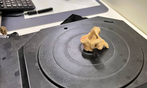
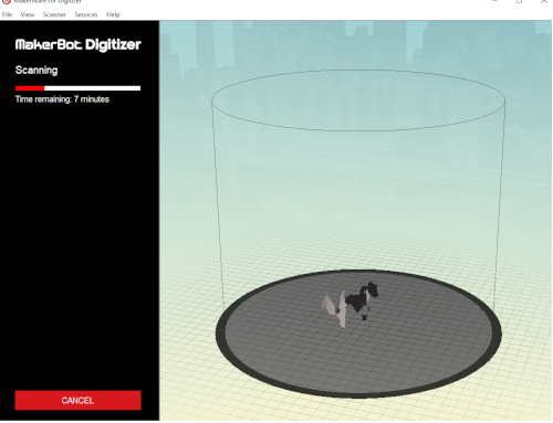
Then I just pressed start scan! The platform slowly rotated and I saw the laser passing over the bone. It estimated the scan to last for about 7 minutes and it did. It was fun to see the bone taking it's shape on the screen bit by bit.
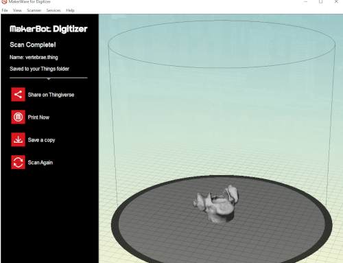
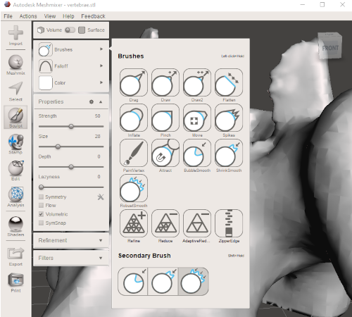
I was pretty happy with my first scan as an experiment. I didn't yet try to print this because there is a lot to do this week. But I opened the scan in Autodesk Meshmixer to improve it a bit. For example, the scan left some funny spikes into the facets of superior articular process.
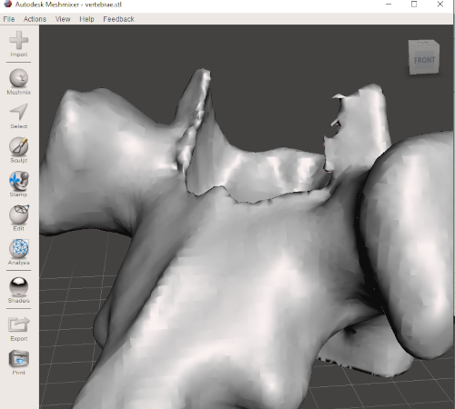
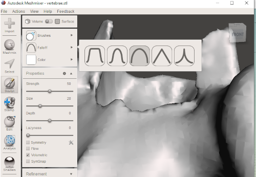
In Meshmixer I made them back to smooth with Brush tool and Falloff. The Falloff flyout allows you to select different falloff shapes that modulate the strength of the operation you are using, in this case the brush. In these picture you can already see the results.
As a first experience of 3D scanning this was a good one. This program was very easy to use, and it seems that Meshmixer was understandable also. There are a lot of programs, apps and scanners to try out when I have more time.