7. Computer controlled machining
Group assignment for this week:
- Complete your lab's safety training
- Test runout, alignment, fixturing, speeds, feeds, materials and toolpaths for your machine
The documentation of group assignment can be found on our group work page.
In the group work we went through the safety instructions and the milling workflow from making toolpaths to the milling itself. It is important to go through these steps well rested, and it is not worth starting milling if you feel tired, as the risk of making mistakes increases.
As an example of the milling workflow, one of our instructors had designed hangers and milled these from plywood. Our task was also to compare the dimensions in the design with the dimensions of the milled hanger. The dimensions did not differ much from each other, the variation was at most within a millimetre and even that could be more of a measurement fault.
I go through many of the steps in my own documentation related to workflow and safety, but there is more detailed information on the group work page, for example on how to change a milling bit.
Individual assignment for this week:
- Make (design+mill+assemble) something big
"Make something big" week excited me because it immediately sounded like something I could roll up my sleeves and start doing. Even though I've been trying to roll up those sleeves up until now. There has been plenty to do this week as well.
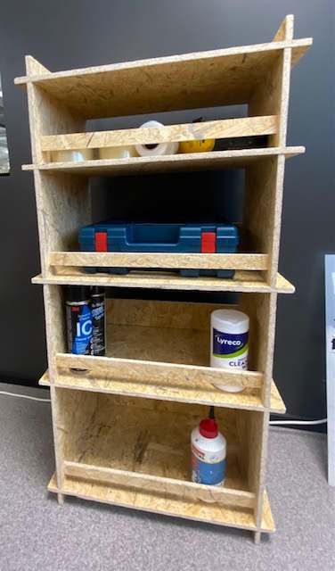
We had OSB reserved for our milling work. I'm not sure I like OSB so much, so I asked my dad if he had a need for some furniture or a storage shelf in his garage. Dad immediately came up with a need for a shelf to store various spray cans and detergents and such.
So I decided to go for it. As a twist on planning and experimenting, I thought I would test a few different but fairly common types of joints. I wanted to see how they would work in this project.
I can already say that there are a few mistakes in the project, so me or you can learn from them. OR try not to be too tired or busy doing 3D design and toolpaths, so these mistakes might be avoided.
3D design
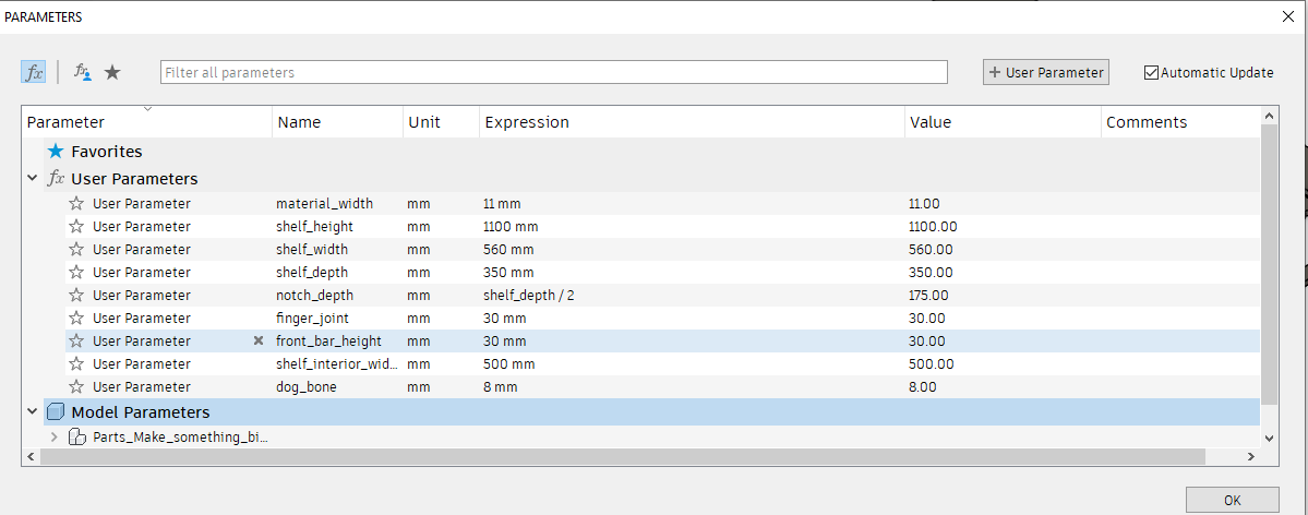
I set the parameters for the shelf dimensions:
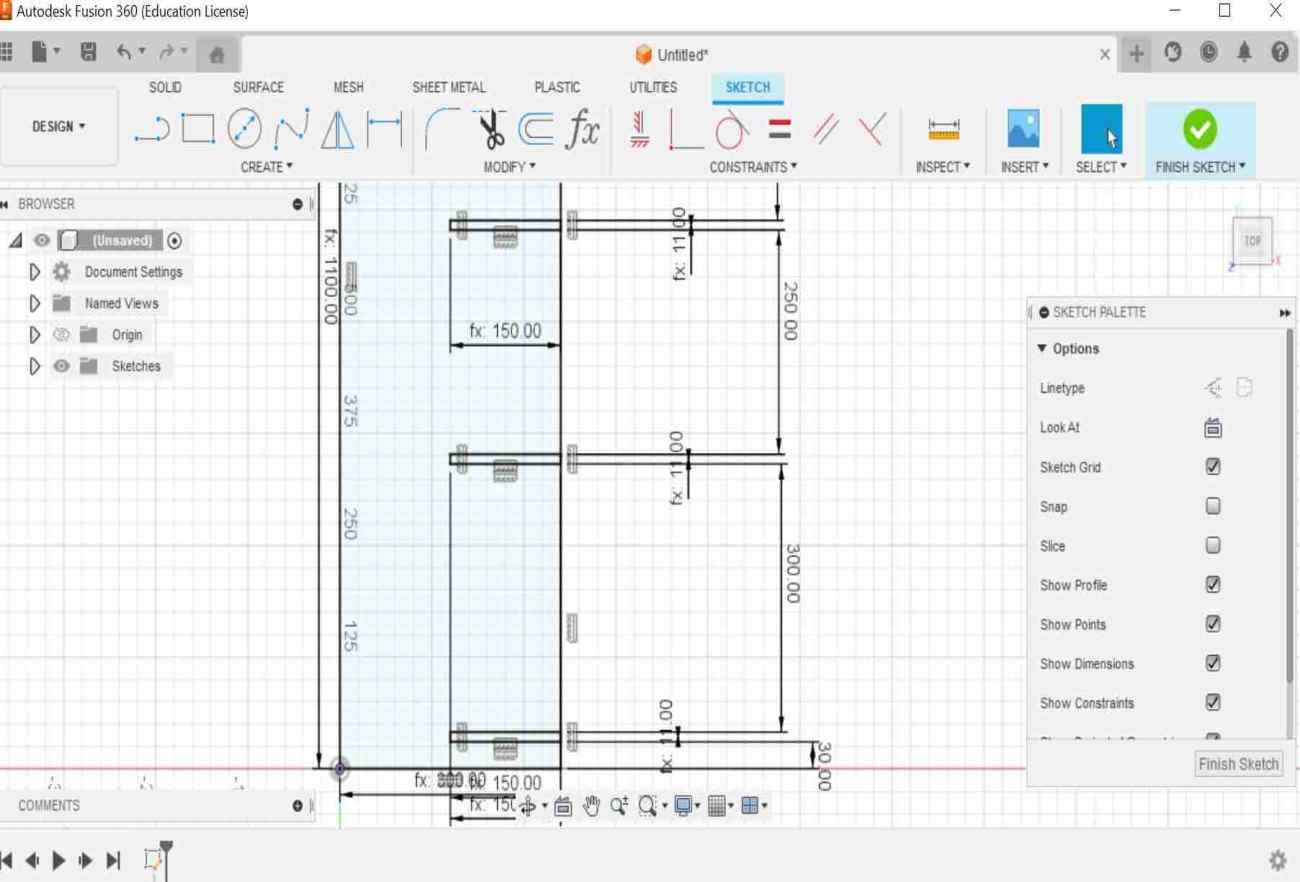
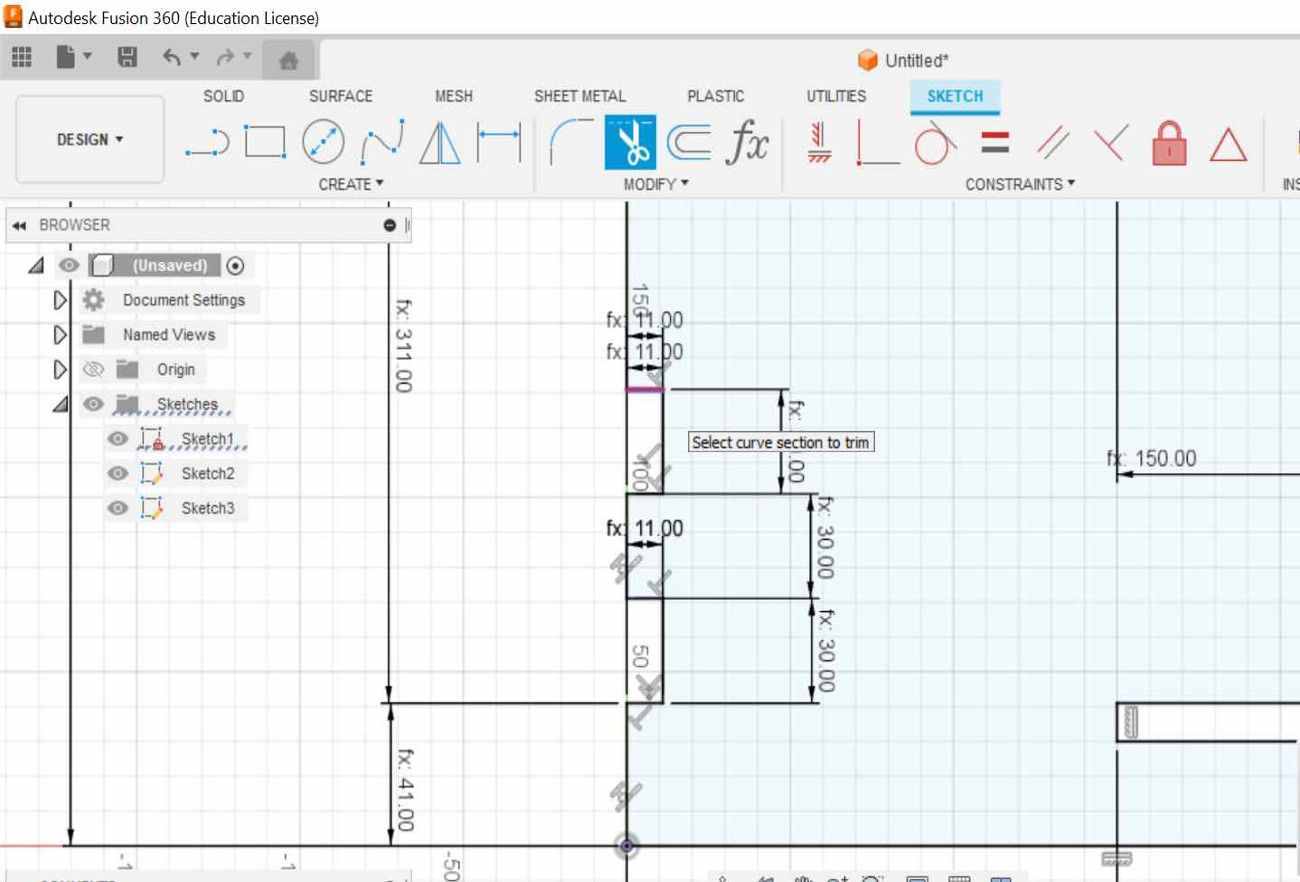
I created four sketches separately for each part of the shelf. For each sketch, I first drew a 2-points rectangle base. Then I edited the details into sketches using the line tool and the trim tool to remove extra lines. Pictures below.
|
|
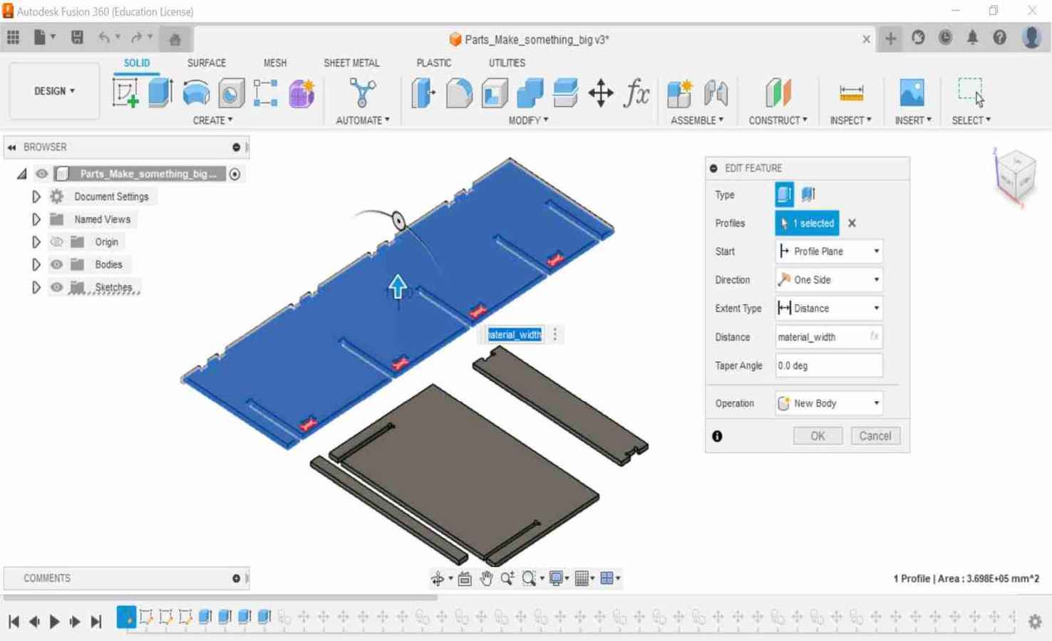
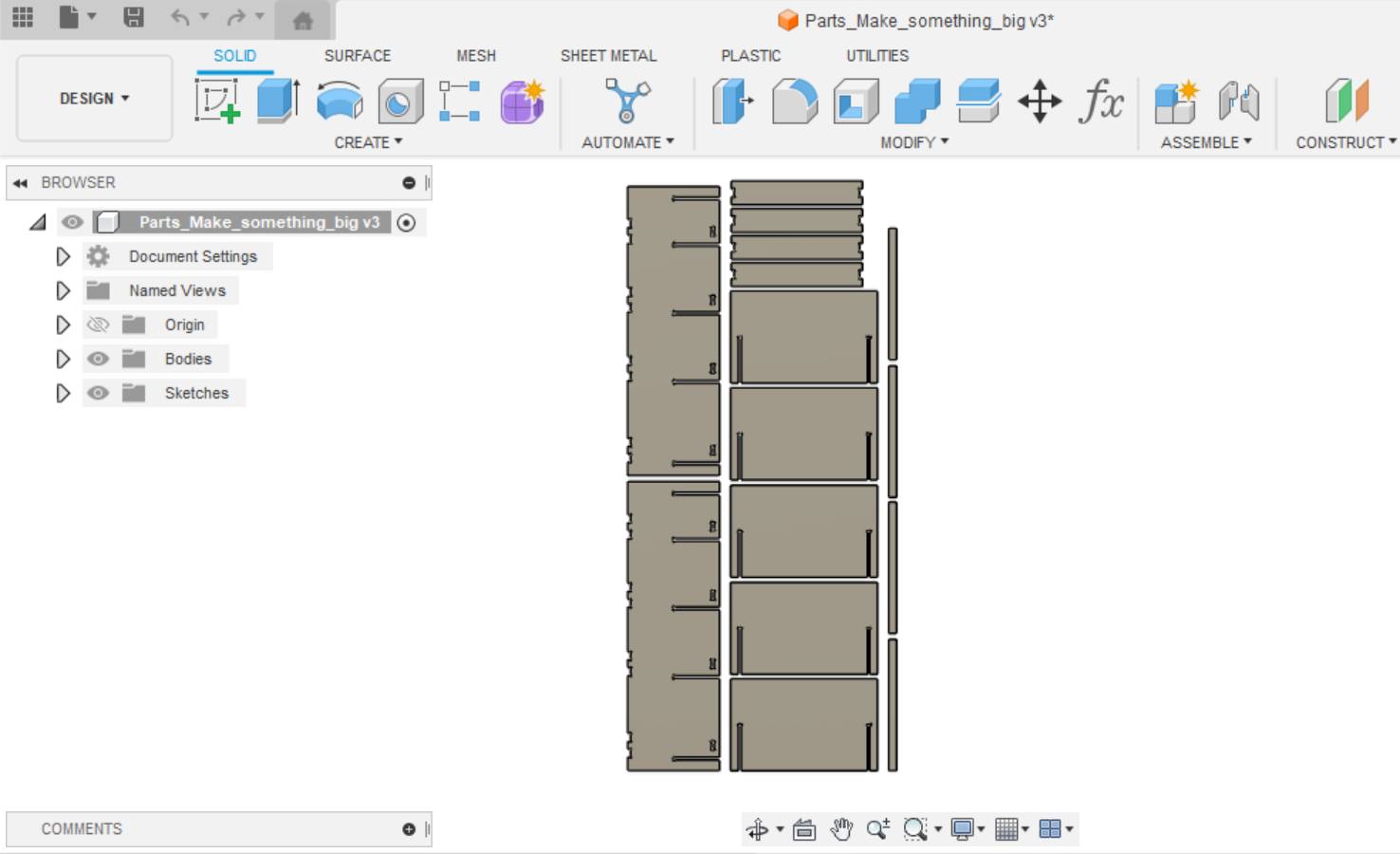
When the sketches were ready, I extruded them to the expected thickness of the material. I copied as many bodies as I needed and put them in order. Pictures below.
|
|
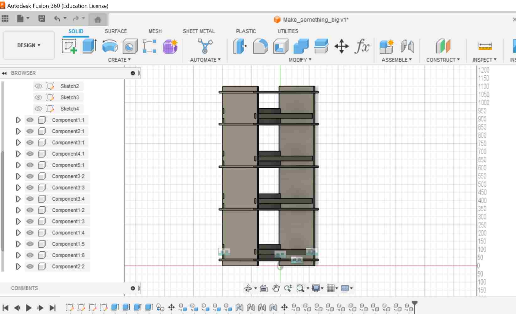
I haven't done many assemblies in Fusion before, so I wanted to see what the shelf would look like when assembled. At the same time, it was easy to check if the pieces were the right size. I used Joint tool from Assemble menu and chose the faces I wanted to be against each other. Left picture below.
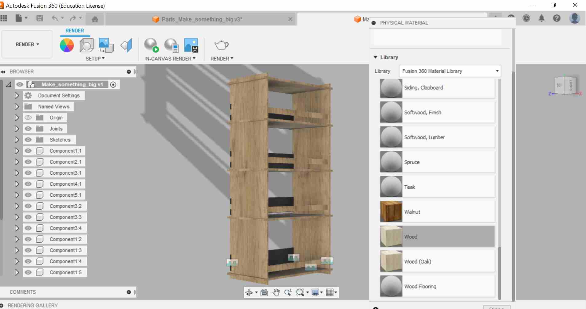
The next thing I wanted to try was rendering, because I had never tested it before. I changed Design workspace in the top left corner to Render workspace. From Setup I chose Physical Material and assigned the wood material for shelf. This was easier than I thought it would be. Right picture below.
|
|
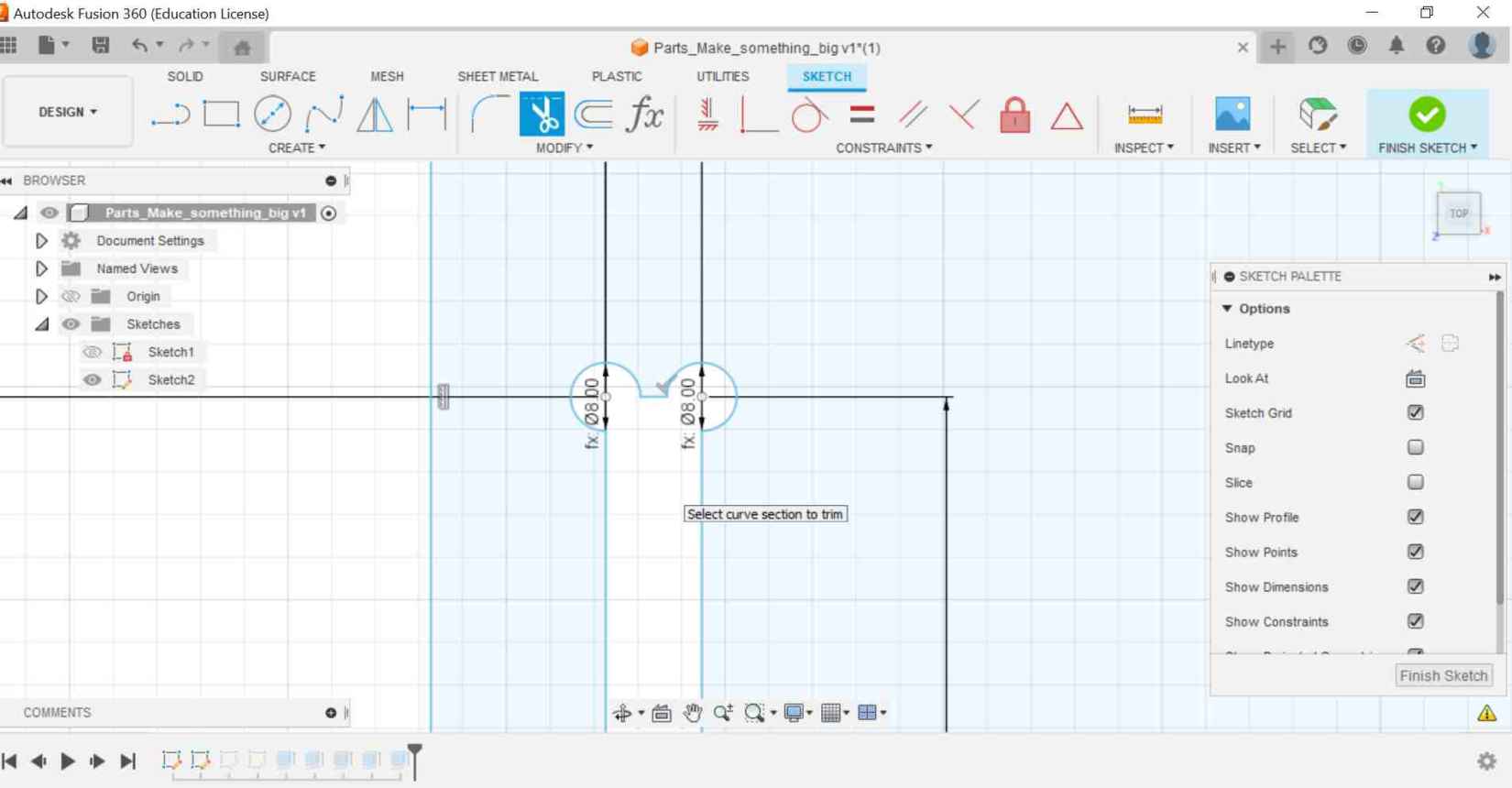
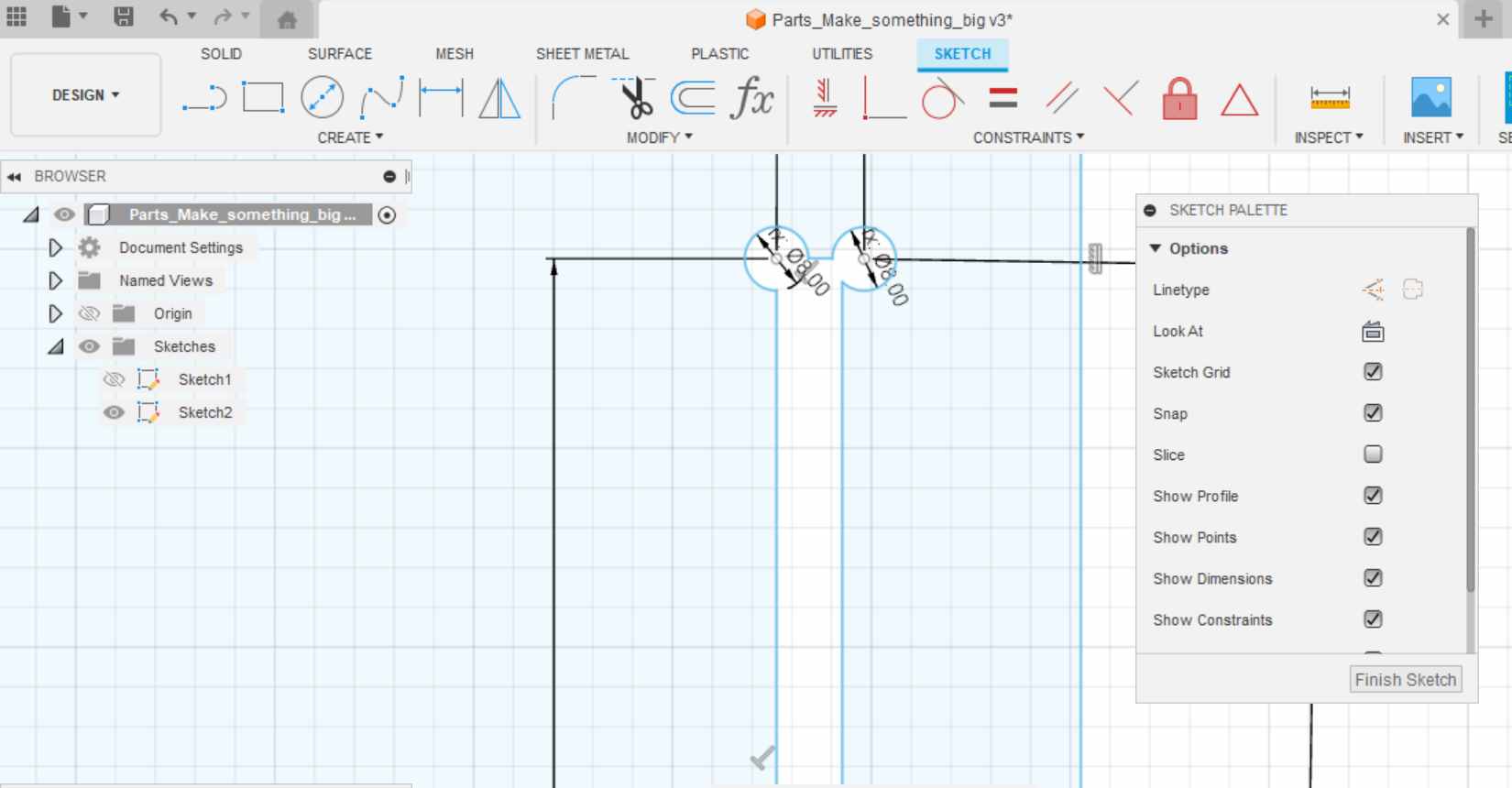
As a last step before local lessons, I decided to make dog bones for all the inner corners. You can already see that I did them wrong, not thinking that an 8 mm milling bit will not fit to make dog bones, because the gap in the corner is so narrow. Gap is only 5.781 mm width, so the 8 mm endmill could not get in. And also the circle should be a bit bigger than 8 mm in diameter. Left picture below.
Already at this point I will show you another mistake, which I didn't notice until I was milling. At the beginning of local lesson, I changed a few dimensions and parameters while talking to the instructor about the strenght of the material. When I changed the dimensions, the notch line on one part had moved inward and I didn't notice this. This caused extra work in the finishing process when I had to make the notches wider by hand. So it's worth double checking the dimensions if you don't want extra work! Right picture below.
|
|
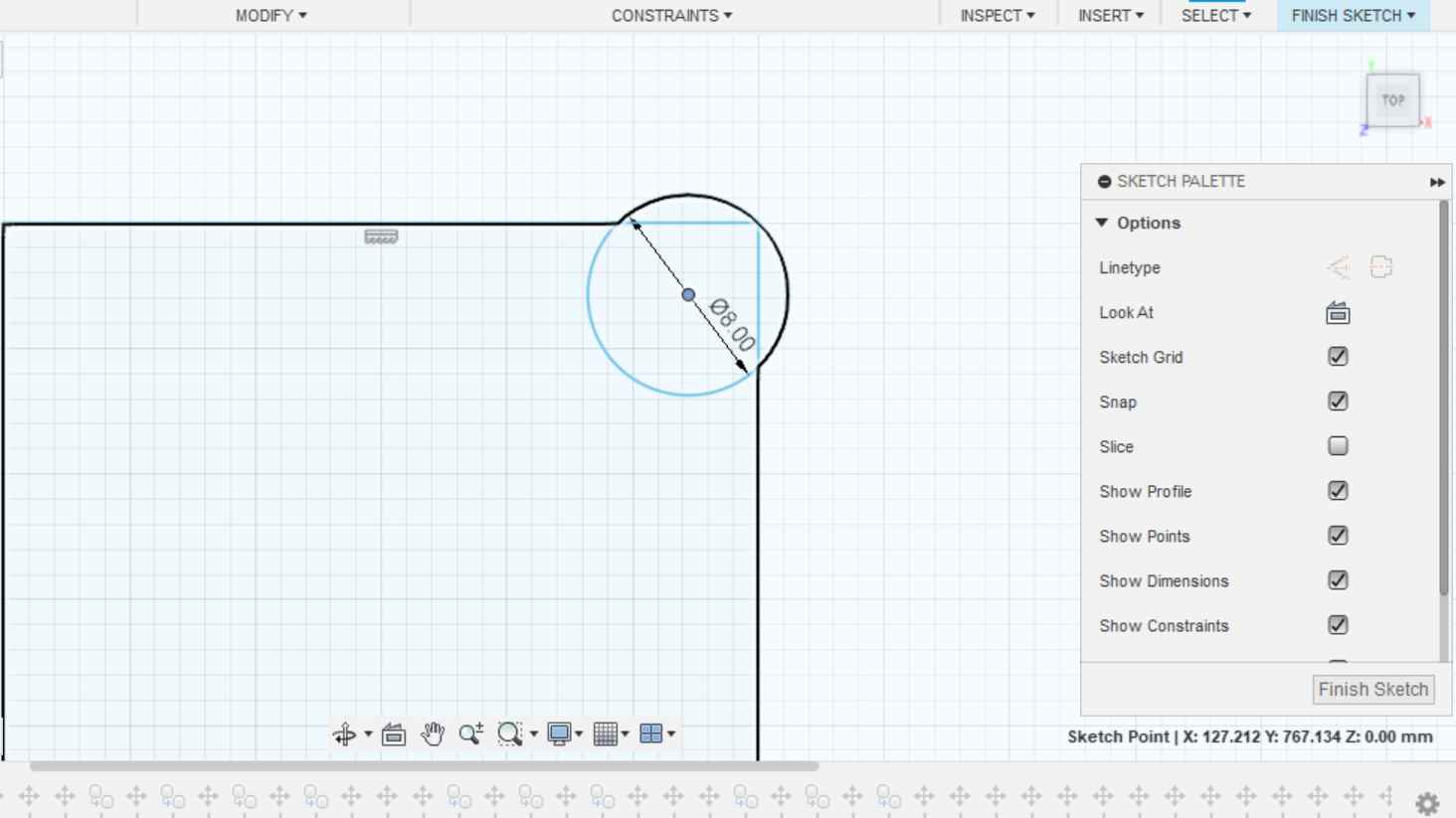
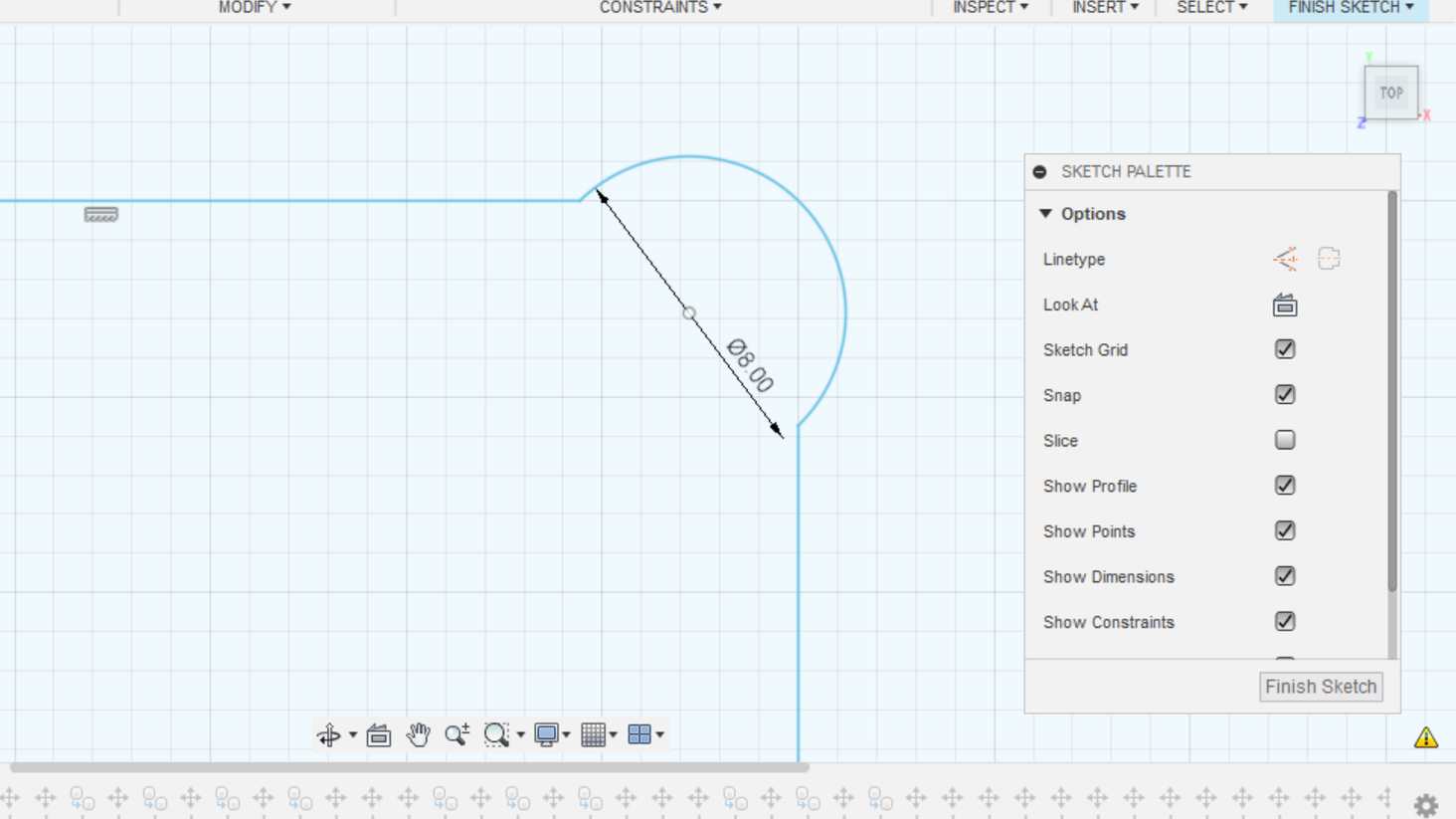
The pictures below show an example of a correctly designed dog bone, where the circle is moved more to the inside of the corner and the circle's circumference passes through the corner. In this case, the dogbone can be successfully milled and the holes in the corners are not big. Tips on different types of CNC dog bones can be found on the Roskilde Fab Lab website.
|
|
Download shelf 3D design F3D file
Toolpaths
After the 3D design was complete, I changed the Design workspace to Manufacture. It's time to set up toolpaths for milling.
Setup
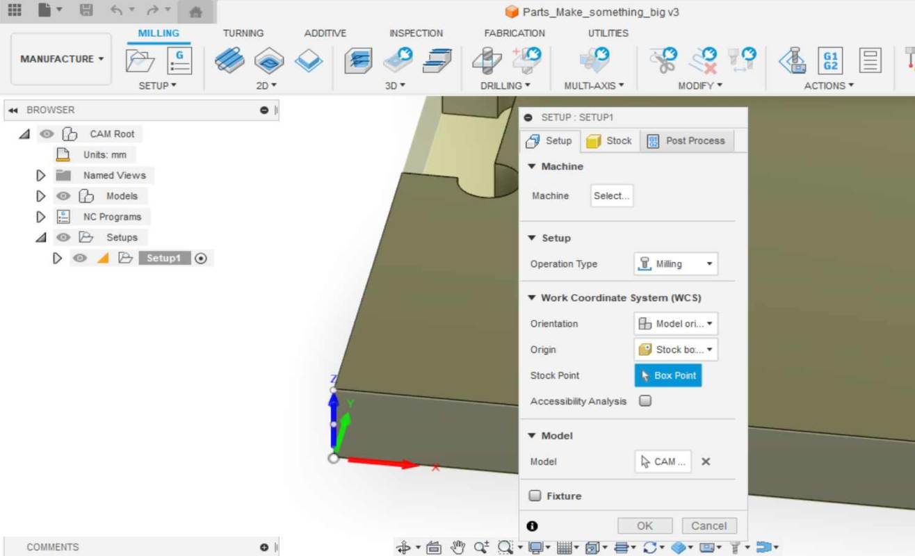
The first step was to create a New Setup from the Setup menu.
In Setup tab I selected origin box point to be the bottom left corner. I also check the axis and in my design they were in right orientation from the start. If the axis are not in right orientation, they can be changed from the "Orientation" drop-down menu. There is option "Select X and Y axes".
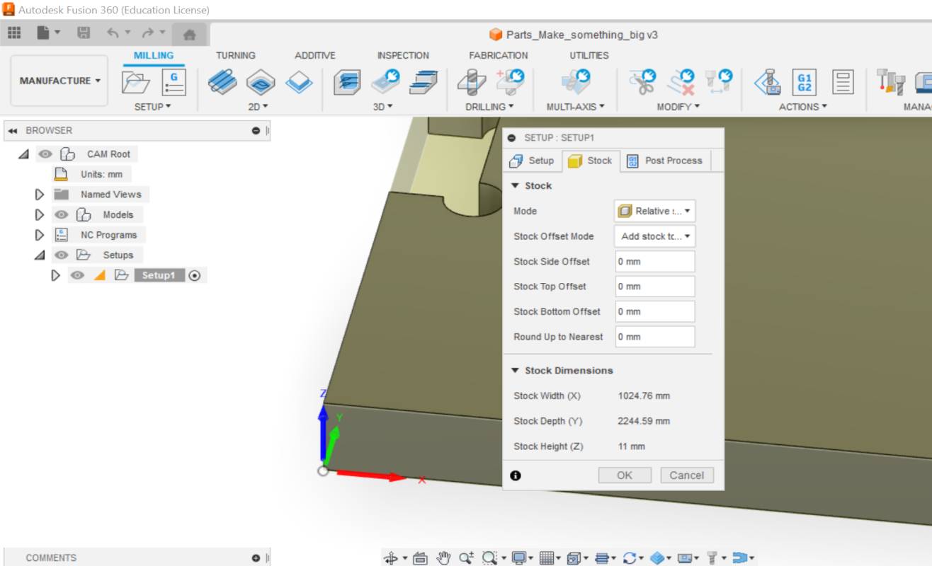
In Stock tab I checked the stock dimensions to ensure that the design will fit the OSB sheet. The stock height is also very important to check, that all pieces are at the same plane and the same thickness as they should be. Picture below right.
It's a good idea to take a picture of the dimensions in the Stock tab or write them down, so they're remembered until the milling process, when you place your design on the sheet to be cut.
|
|
2D Pocket
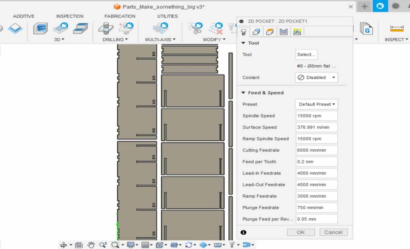
Next step, I selected 2D Pockets in 2D menu. I was going to create toolpaths for slots in my design. In Tool tab I selected the tool from tool library.
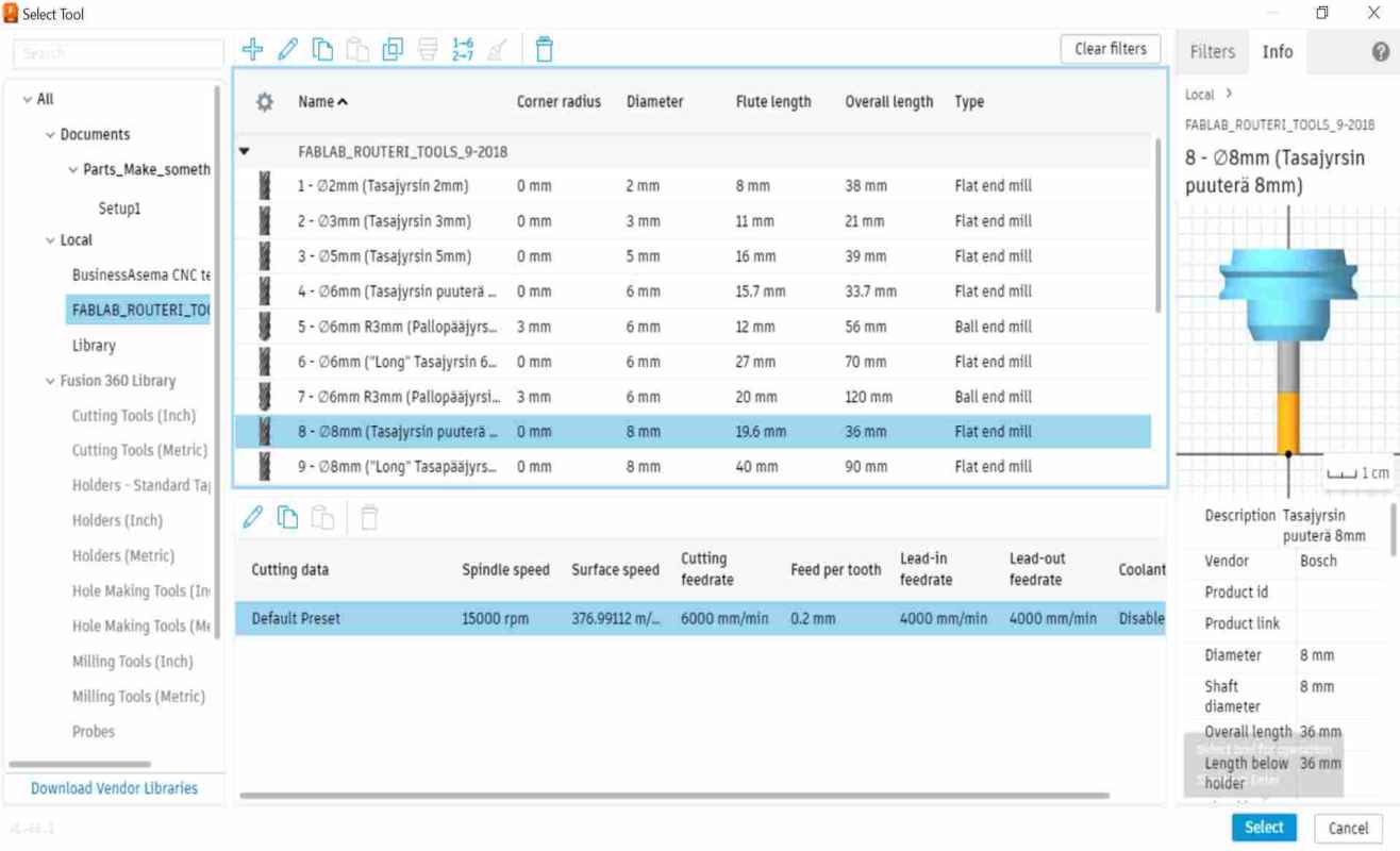
We had downloaded FABLAB_ROUTERI_TOOLS_9-2018 library to computer, in which were default setting for tools that we have in our Fab Lab. I selected the 8 mm flat end mill for wood that we were recommended to use in our works. Pictures below.
|
|
In Geometry tab I selected the 8 slots in my design. Picture below left.
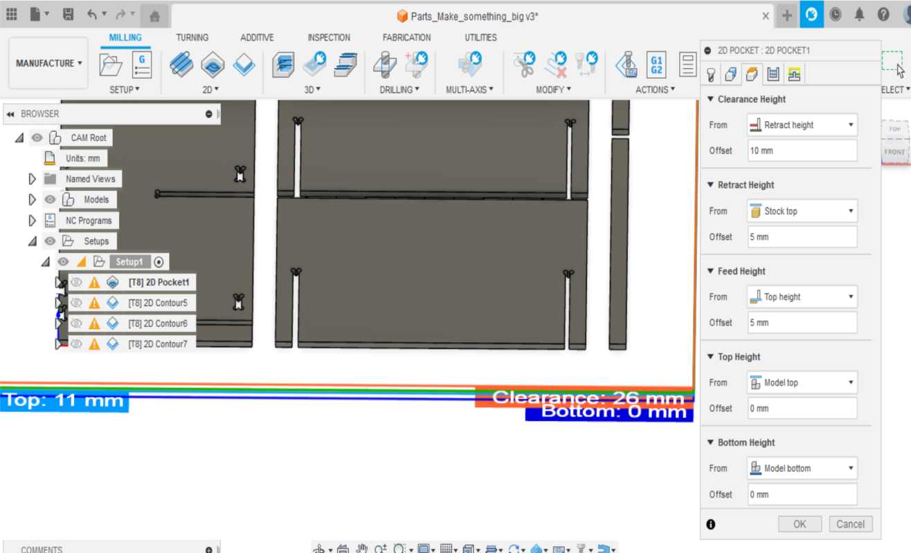
In Heights tab I:
- set the "Top Height" to Model top.
- set the "Bottom Height" to Model bottom.
I check from the design that the bottom layer is 0 mm and to top is 11 mm. I chose Model top and Model bottom settings because the milling went through the material. Picture below right.
|
|
In Passes tab I:
- activated "Multiple Depths" menu.
- set 3 mm to "Maximum Roughing Stpedown".
- activated "Use Even Stepdowns".
In Linking tab I:
- deactived Lead-In (Entry) and Lead-out (Exit)
- set the "Ramp Type" to Plunge
Now the Pockets setting was set.
2D Contour
Next, I made 2D Contour for all pieces in my design. I navigated to 2D -> 2D Contour and started to set settings. I'll first tell you in general what settings I set on each tab, and then come the specifications I used in Geometry tab for each 2D Contour. I made separate 2D Contour toolpaths for each group of pieces of different sizes.
In Tool tab, I selected the same milling bit as before.
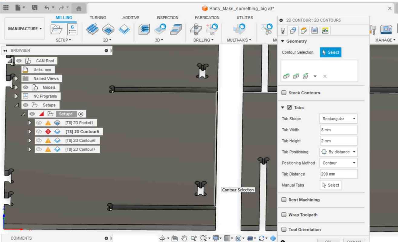
In Geometry tap I:
- selected the pieces to be milled in Contour Selection.
- activated "Tabs" menu and set the "Tab Distance".
In Heights tab I:
- set the "Top Height" to Model top.
- set the "Bottom Height" to Model bottom.
I check from the design that the bottom layer is 0 mm and to top is 11 mm.
In Passes tab I:
- activated "Multiple Depths" menu.
- set 3 mm to "Maximum Roughing Stpedown".
- activated "Use Even Stepdowns".
In Linking tab I:
- deactived Lead-In (Entry) and Lead-out (Exit)
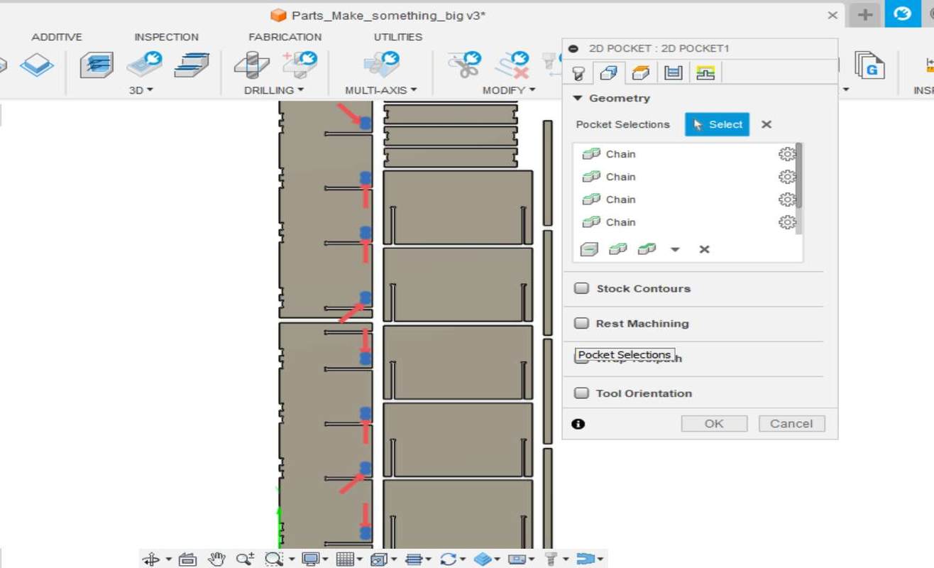
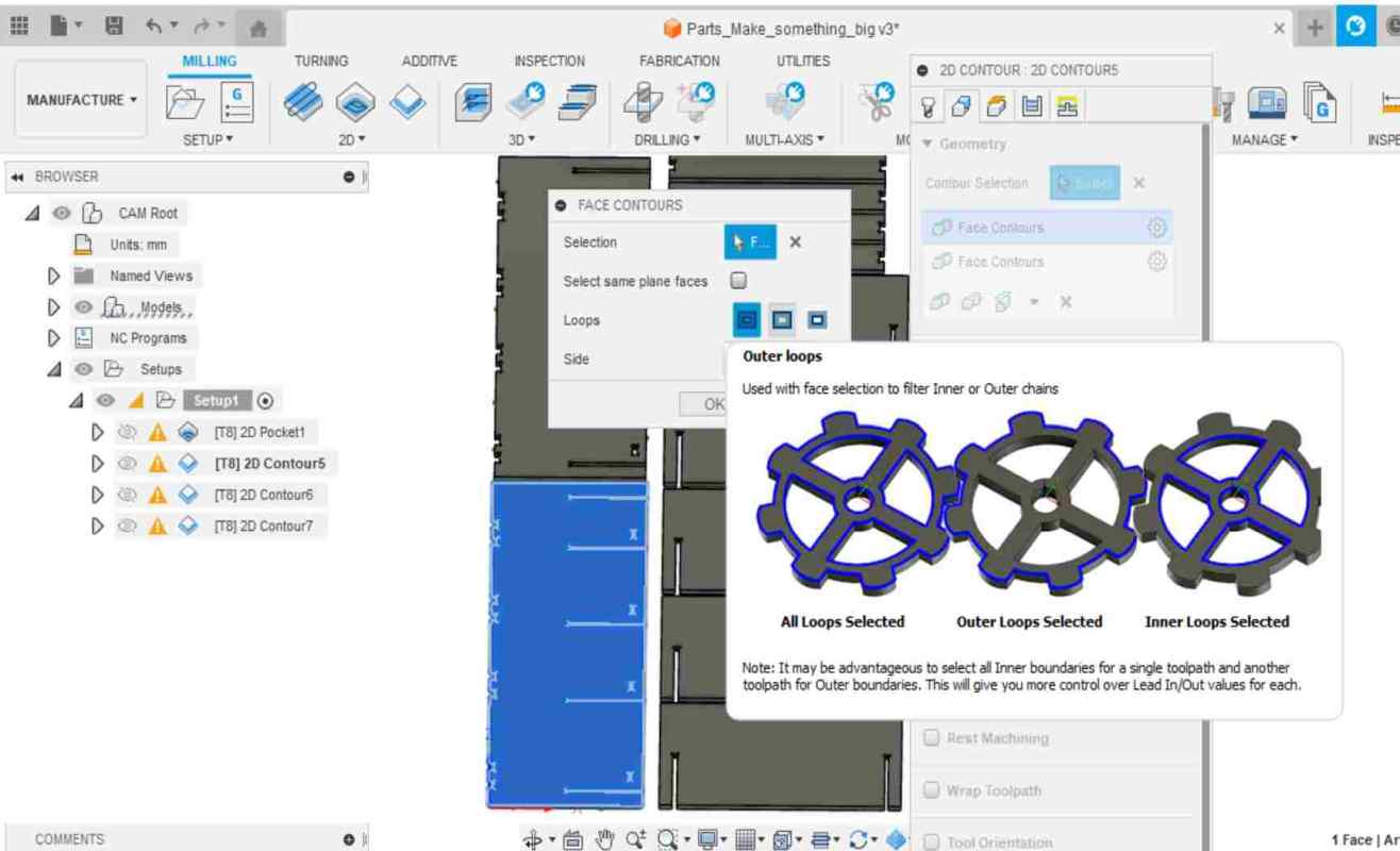
I started with the biggest shelf pieces. In Geometry tab I tried to select the chain of the biggest pieces. The problem I faced was that I couldn't select the chain of the whole piece. I could only select parts of the chain. Picture below left.
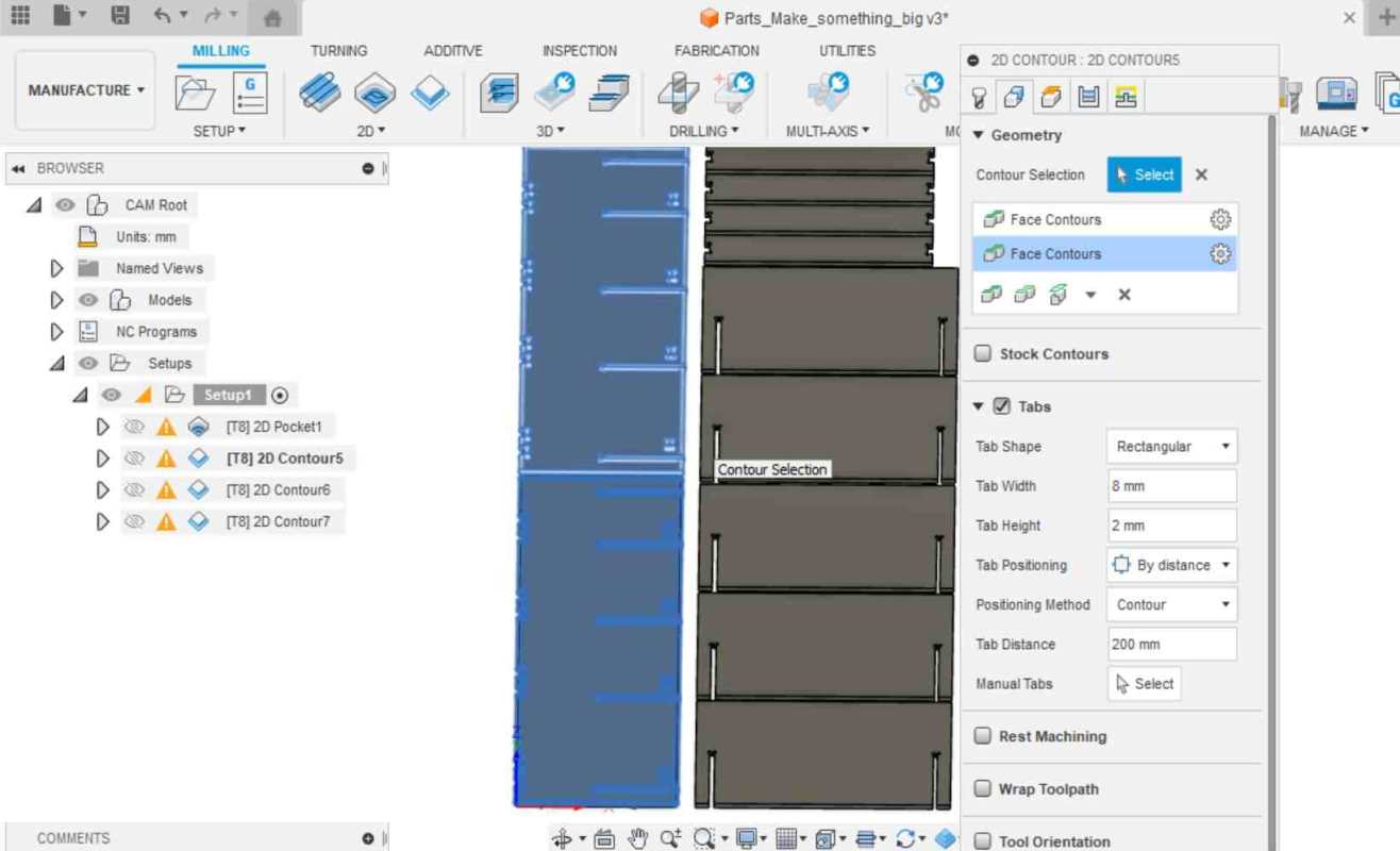
I found the solution to the problem by selecting the whole face of the piece instead of a chain and going to the settings from the settings icon next to selected "Face Contours". Picture below right.
|
|
In the settings I selected "Outer loops", in which case the selection did not take into account the inner slots. This way I managed to get the right milling setting for the outer edges of the biggest pieces.
I activated Tabs menu and set the "Tab Distance" to 200 mm. Settings can be seen in the picture above right. Other settings tabs I set up as I told above.
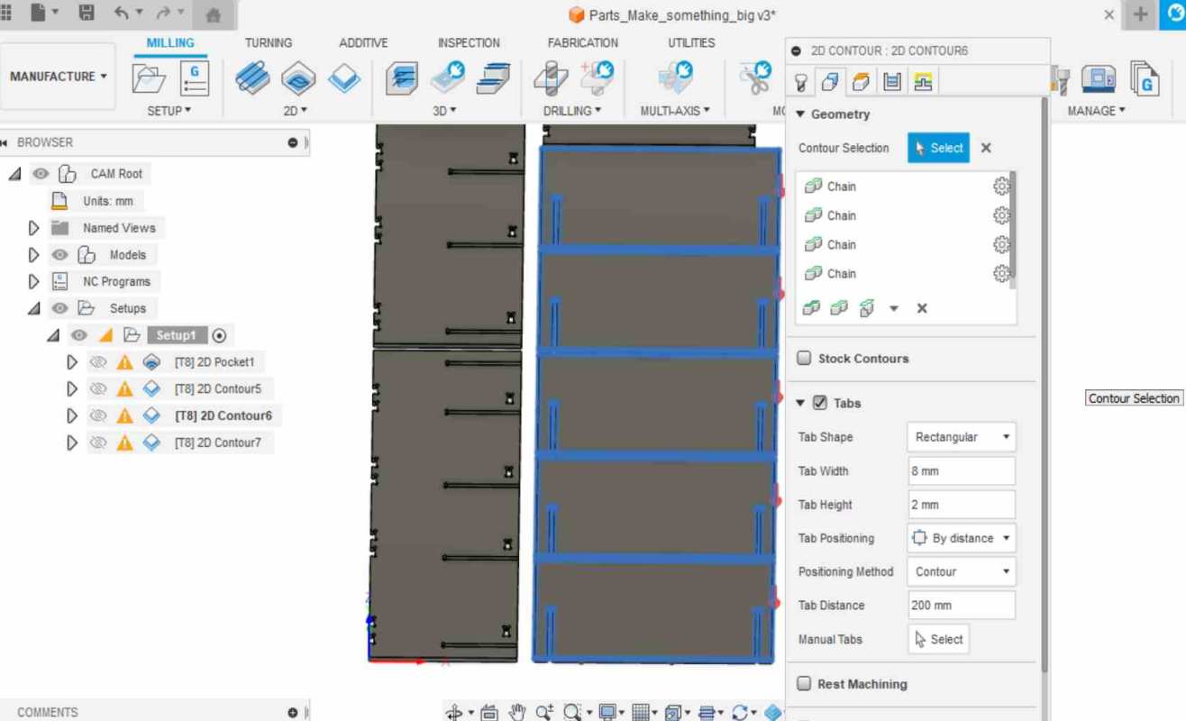
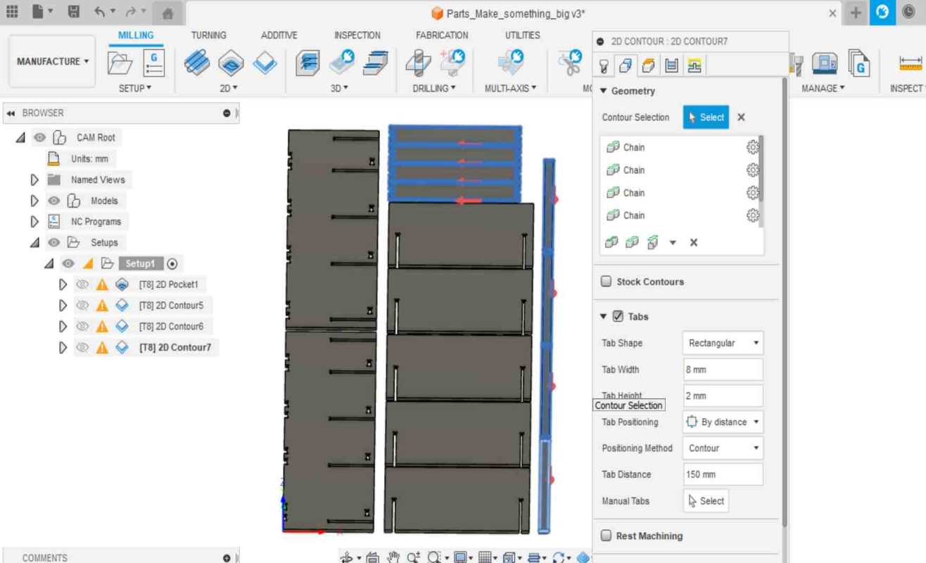
So I made three different Contour toolpaths in all; for the bigger pieces, for the medium pieces and for the smaller ones.
Below you can see the Contour Selections for medium (left) and smaller (right) pieces. For medium and small pieces, I was able to select the whole chain of the pieces as the Contour Selection. Otherwise the settings was as above, only the Geometry tab had some refinements: in the Tabs menu, I set "Tab Distance" to 200 mm for medium sized pieces and 150 mm for smaller pieces.
|
|
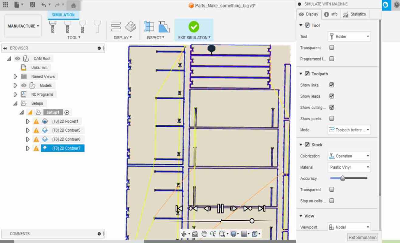
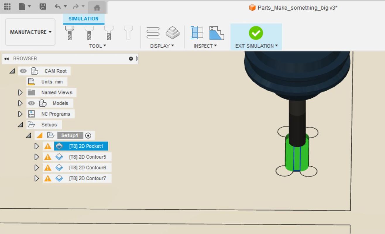
Next was time for the simulation. I selected the Setup1 from the left, so that all the toolpaths I made would be taken into account at the same time. I navigated to Actions -> Simulate. Perhaps the view went too quickly and too far away, the overall simulation looked good, all the pieces were there in the simulation milling. Picture below left.
BUT, if I had looked closer, I would have noticed at this point that the dogbones were incorrectly designed and they would not succeed in milling. Picture below right.
So I didn't notice dogbones at this point, I just looked at the overall simulation and thought it looked good, and moved on.
|
|
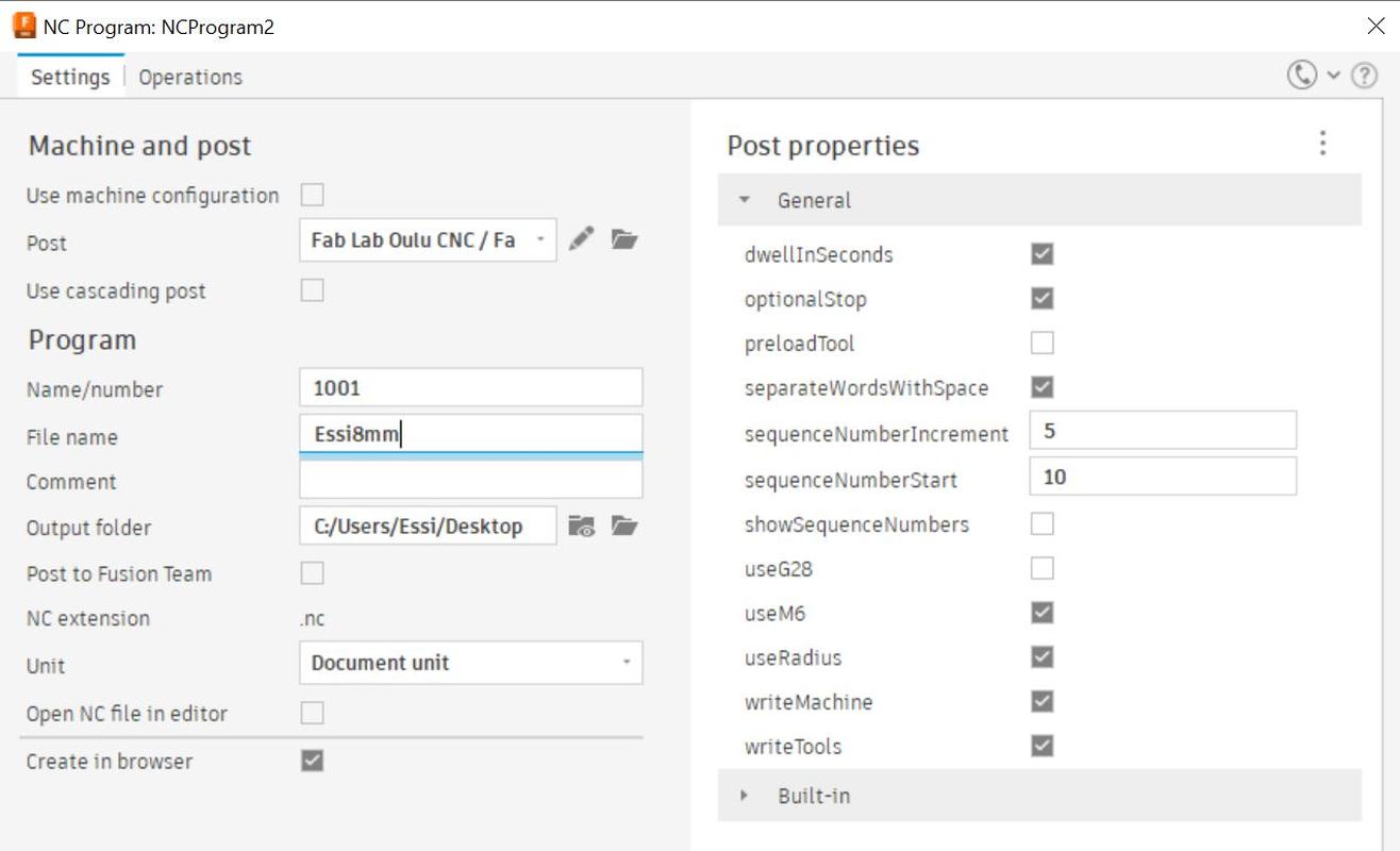
The last step in Fusion was to save the nc.file from the design. I navigated to Actions -> Post Process. Here I named the file with my name and the milling bit size I was using, so that the file was easy to find. Picture below. Then I press post and got the .nc file for milling. I copied the .nc file to memory stick and went to the milling machine.
Milling
The milling machine model in Fab Lab Oulu is Rensi E2-1325 with a vacuum table.
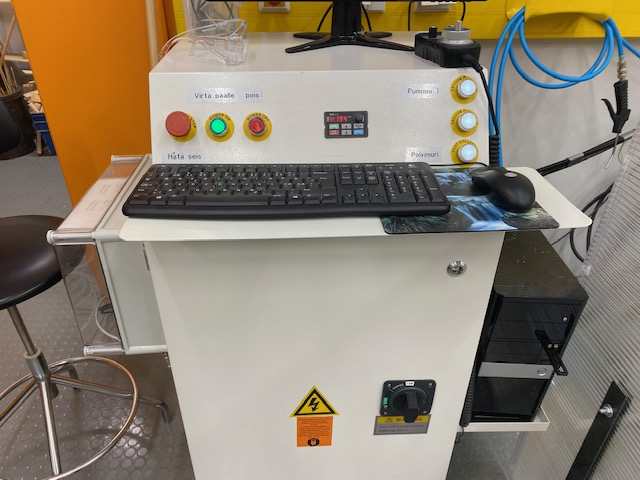
The first step is switching on the machine. At the bottom of the control unit is the main power on the right and at the top on the left is another green power on button to turn on the machine's power. You can also turn on the vacuum table at this point or at the latest when you calibrate the z-axis. The buttons to turn on the vacuum table are on the top right of the control unit. Picture below.
I didn't need to change the milling bit at this point, as the right 8 mm bit was already in place, but on our group work page we explain how to change the milling bit.
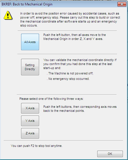
I opened NcStudio on the computer. First it warned with the "Back to Mechanical Origin" window, I pressed "All Axes" and all axes move to the Mechanical Origin. Then I opened and loaded my .nc file from File menu.
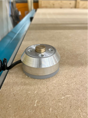
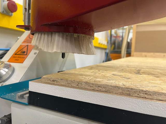
Next, it's time to calibrate the z-axis. The OSB sheet should be moved so that the mobile calibrator can be placed on top of vacuum table. Picture below left. At this point, it is important to check that the vacuum table is on to ensure that the calibration is correct. I think I personally forgot to check the vacuum table before calibrating the z-axis, because the pieces were stuck tightly to the OSB sheet after milling.
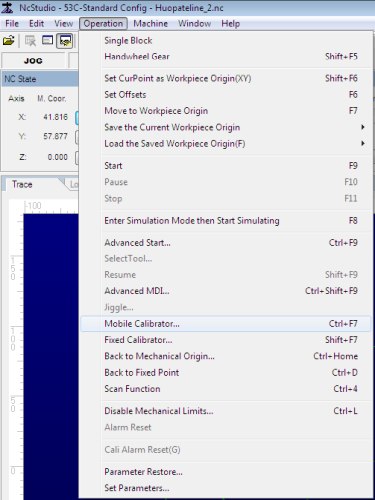
The mobile calibrator should be placed just below the milling bit. When it is in place, from the NcStudio Operation menu, select the mobile calibrator. Picture below right. "To perform a calibration action, Continue?" window pops up and when you press yes, the milling head starts to lower and does the calibration when it touches the mobile calibrator.
|
|
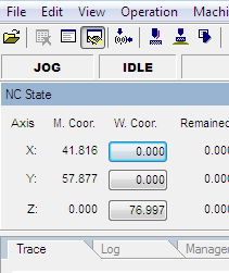
Then, I set the origin by first moving the milling head along the x and y axes to the lower left corner of the sheet. First I moved the milling head on the program panel by selecting the jog setting and pressing the X, X+, Y- and Y+ buttons. Picture below.
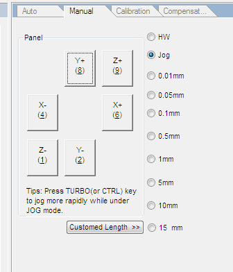
I also moved the milling head with the hand wheel. From the program panel I chose HW setting. Then from the hand wheel I selected the axis and by turning the wheel I was able to move the milling head. Picture below left. I stopped the milling head when the milling bit was near the bottom left corner. Picture below right.

|
|
I zeroed X and Y axes by clicking on the buttons under the W.Coor. Picture below.
Before you start milling, it's a good idea to run a simulation in NcStudio to see if everything goes well. The simulation button can be found in the toolbar at the top of NcStudio. I didn't remember to take a picture of the simulation, but it looked good.
The last step before you start the milling is turn on the dust collector and make sure you have worn the safety glasses and hearing protection. Then you can press play on NcStudio. Note that next to the play button is a stop button, which you press if something seems to be going wrong.
During the milling process, the machine cannot be left alone, you must keep an eye on how the milling is going all the time.
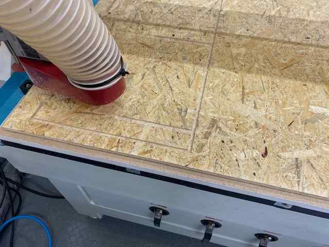
It is also important to listen to the sound of the milling, if the machine starts to "whistle", the spindle speed should be lower. In NcStudio the speeds can be changed from the sliders during the milling process if they are not ideal. Picture below.
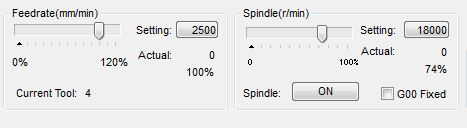
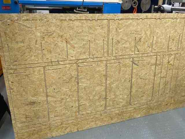
The milling process took about 30 minutes. At the end, I turned off the machine, removed the material from the vacuum table and cleaned the machine environment.
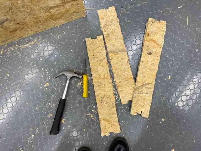
As you can see in the picture below left, the pieces were still well attached to the OSB sheet. I used a saw as well as a knife and a hammer to get the pieces off the sheet. Picture below right. This made a lot of extra work. And probably because of a z-axis calibration mistake.
|
|
Finishing and assembly
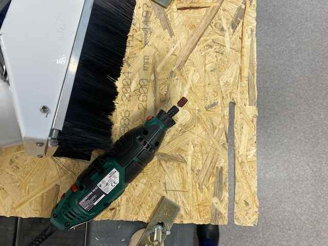
After getting the pieces off the sheet, the hard work of finishing began. In the Fab Lab Oulu at the university, I used a belt sander to sand the side of the pieces. Then I used a dremel for a while to sand the notches and slots, but then I found that a file was better. When I used the dremel, I kept the dust collector close by to get as much OSB dust out of it as possible. Picture below left.
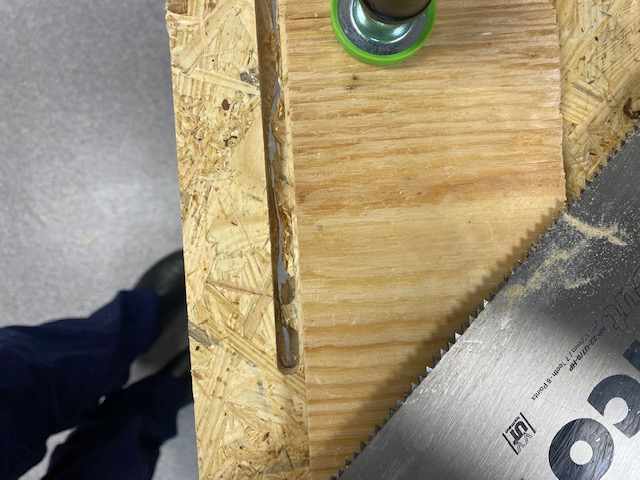
I also tried to make too small notches wider with a dremel and file. However, I found that a saw was the quickest and easiest way to make the notches wider, and I finished them using file. Since I knew that this shelf would be used for storage in the garage, I wasn't too careful with the finishing, so there might be small holes and scratches here and there. And let's face it, this extra work was getting pretty frustrating at some point, so I was also glad that the shelf was only going to be used for storage in the garage. :D Picture below right.
|
|
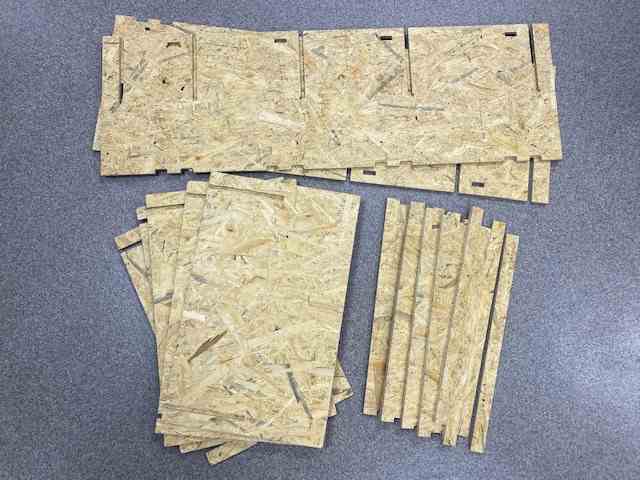
Once I had the pieces cleaned up, I started testing the assembly piece by piece. I sanded the joints to fit together and marked the pieces with matching joints so I knew which pieces went where. Picture below right.
|
|
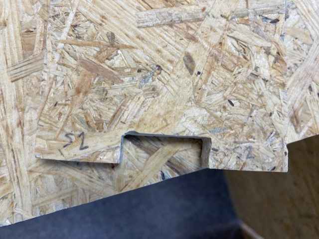
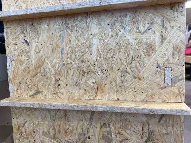
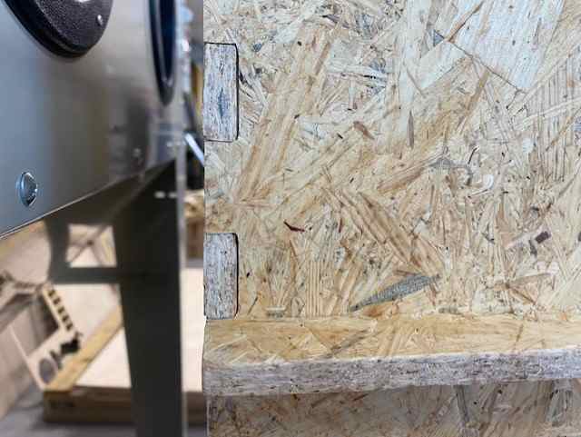
Below you can see the shelf assembled and more detailed pictures of the joints. The lack of dogbones made it a bit extra work, but on the other hand, there weren't as much (big) holes in the corners of the slots and notches as there would have been with dogbones.
|
|
Overall, however, I am happy with the finished shelf. Picture below. And so was my dad when I sent him a picture of the shelf. It was interesting to try out the different joints, they all seemed to work ok. Of course, I made my own changes to them by sanding and filing... But the shelf stays assembled without adhesive or screws and is also pretty stable.