Week 3:Computer Controlled Cutting
Tasks for this week
Group assignment
- characterize your lasercutter’s focus, power, speed, rate, kerf, and joint clearance
- Document your work to the group work page and reflect on your individual page what you learned
Individual assignments
- Design, lasercut, and document a parametric press-fit construction kit, which can be assembled in multiple ways. Account for the lasercutter kerf
- cut something on the vinylcutter
Group Assignment
One of the useful things I learnt this week was how to set up tests for a material to look at the power and speed settings required for cutting. This will come in handy for my Fab Lab when I have users bring in a new material.
I also found that I could use a lower power, with less smoke setting for 3mm MDF than what is in the default settings for the Trotec Speedy 360 80W, I can now implement this as a new standard in my Fab Lab, supporting the longevity of the laser as well as reducing the potential for smoke to escape when doing larger amounts of 3mm MDF cutting.
Press Kit Design
FreeCAD
I decided that I was going to continue the heart theme for my parametric press kit.
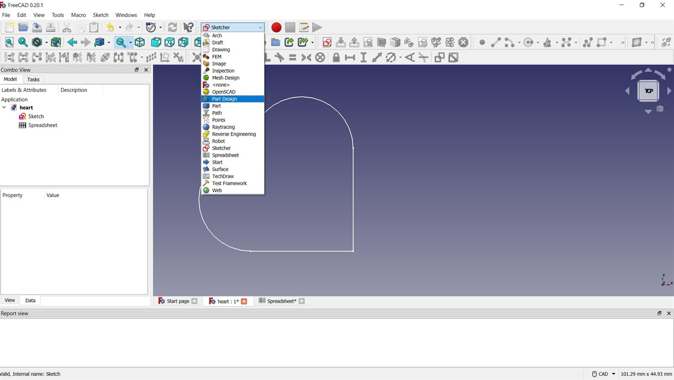
I started out by design the heart in FreeCAD version 0.20.1, it is a free open source software that has a wide range of tools for 3D modelling.
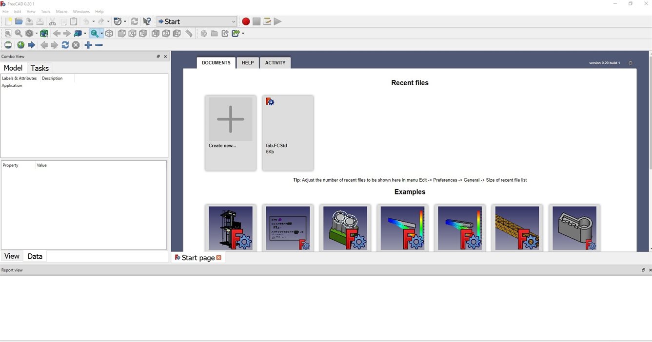
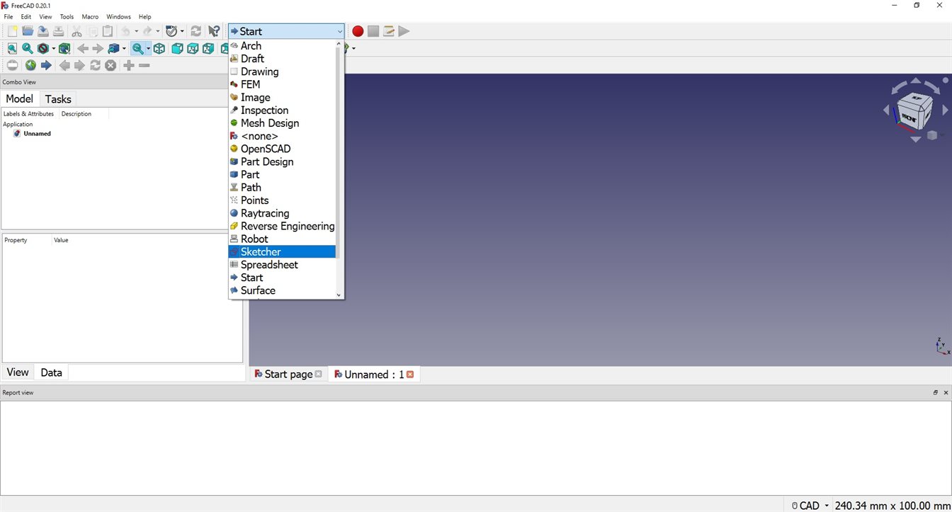
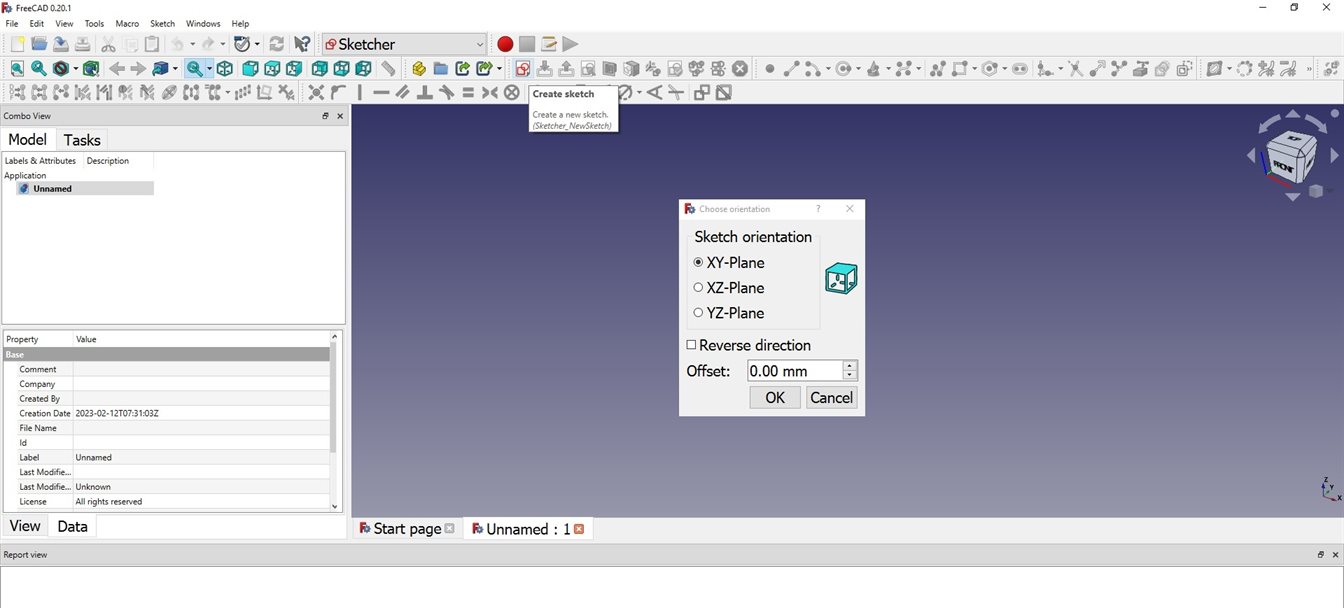
Start by going to the Sketcher workbench. Select create sketch and it will ask you to select the plane you want to draw on (I selected XY-Plane).
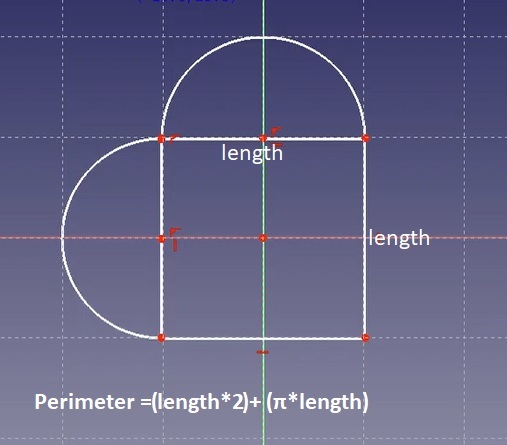
I want to make a heart shaped box for the base. I think using a long strip of material with cuts in it to make it bendy will be able to be used for the side. As such I need to be able to calculate the perimeter of my heart to make it fully parametric. A heart can be made using a square and two semi-circle.
Creating the sketch.
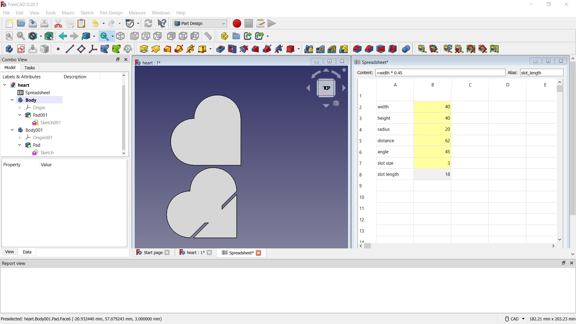
Constraining the sketch and making it parametric using Spreadsheet Workbench.
I realised part way through this process that I would not be able to create a parametric array for the cut lines for the box side using FreeCAD, I will need to use Fusion 360 to do this. However, I decided to finish the sketch in FreeCAD for the other hearts that are going to be able to be made into shapes on top of the box.
Duplicating the sketch and creating the slots on the second sketch.
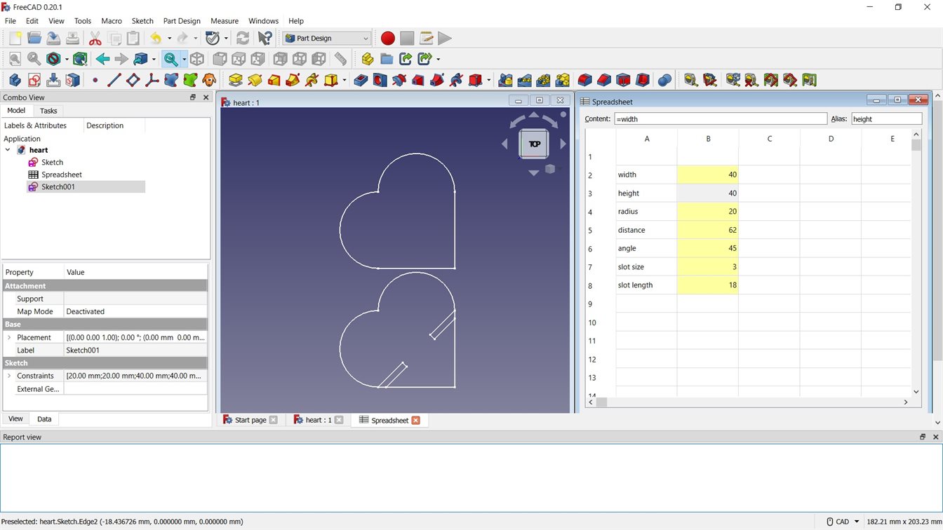
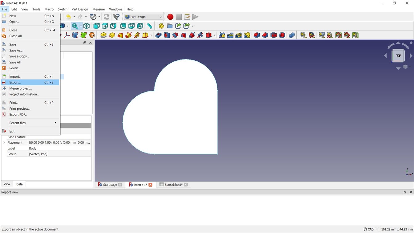
In order to export the sketch to dxf I need to make the sketch 3D using the Part Design Workbench. Then I need to create a body, move the sketch under it and use the Pad tool to make the sketch 3D.
I ran into some issues with the way I had drawn the heart with the slots, the shape was not one continuous line. I had to delete some lines and constraints and do some re-draws to fix it so the the Pad tool would work.
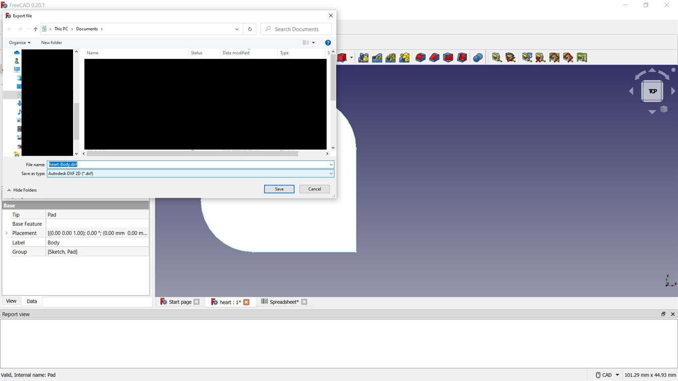
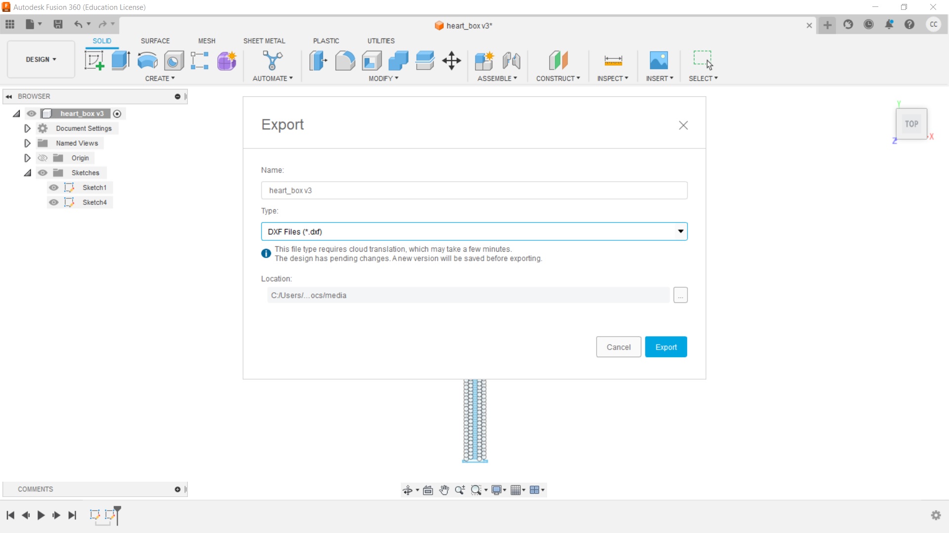
I was then able to export to dxf. With the drawing being parametric I can export different sizes to be cut on the laser cutter.
Fusion 360
As I was unable to make a parametric array using FreeCAD, I made the heart box design in Fusion 360. It is proprietary software from Autodesk and is a commonly used tool for parametric 3D modelling.
I used Fusion 360 2.0.15050 x86_64 to create the following.
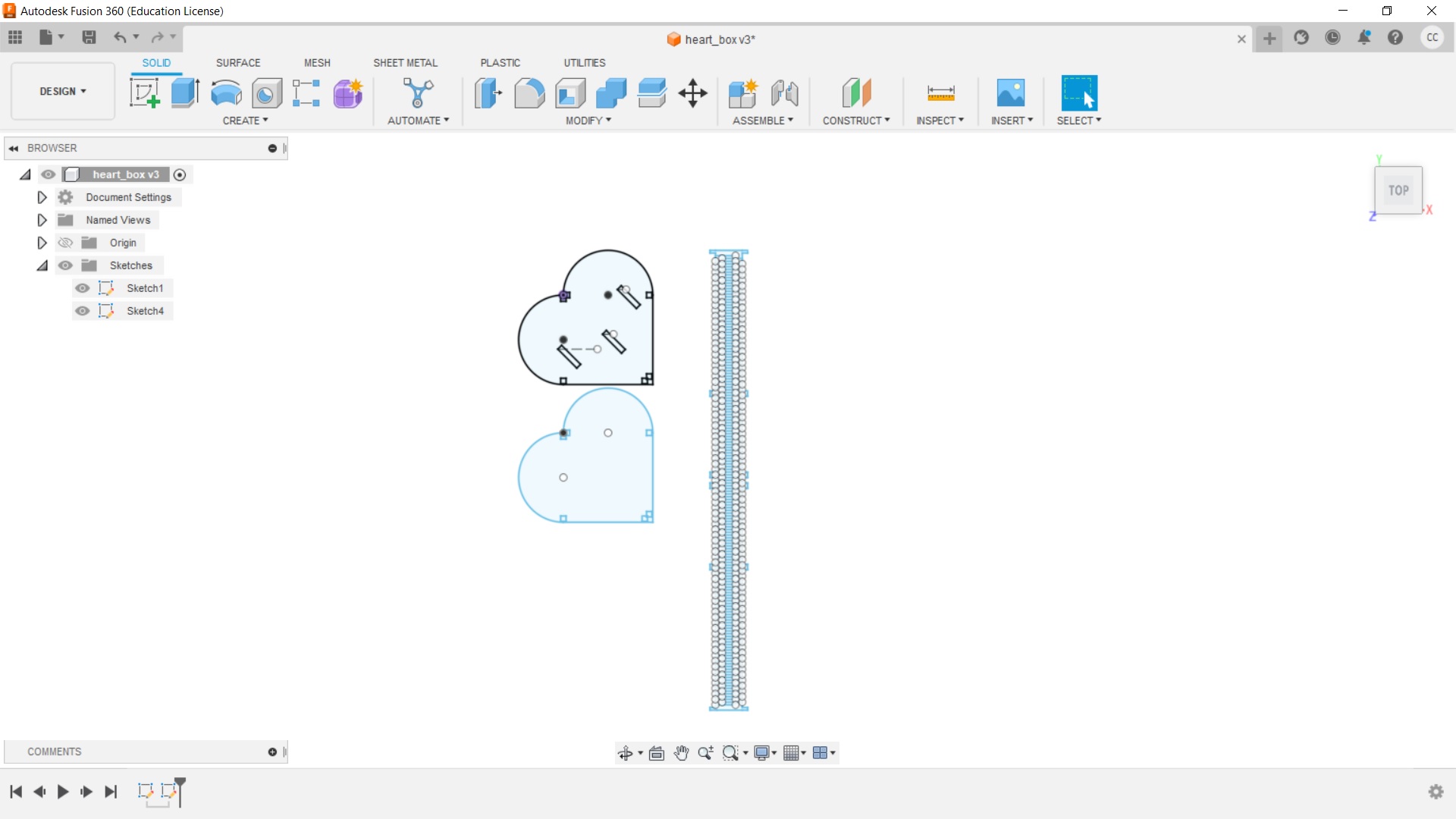
I created a sketch for the top and bottom of the box. I have included videos of what I did, for more detailed guidance about modelling in Fusion 360 see Week 2 Assignment.
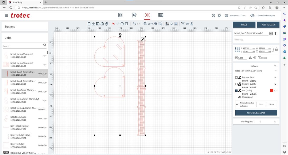
I then created the side, which is to be resized using parameters based on the perimeter of the top/bottom. I based the distance between the cut slots on the thickness of the material I plan on using (3mm MDF), this has been setup to be parametric so if you use a different thickness of material this can be changed.
I forgot to do the tabs for the side to slot into the top and bottom, I ended up redrawing the side to make the tabs. I also ran into a few issues with too many constraints and not having the right constraints. I corrected these by redoing some of the constraints and deleting some.
Note: The rectangular array for the cut lines is fully parametric based, the array gets its distance from the perimeter of the heart (with adjustment for material thickness) and its number based on the distance divided by the spacing (based on material thickness).
I went back into the top/bottom and added in the slots for the side tabs and the slots for the hearts made in FreeCAD to go into.
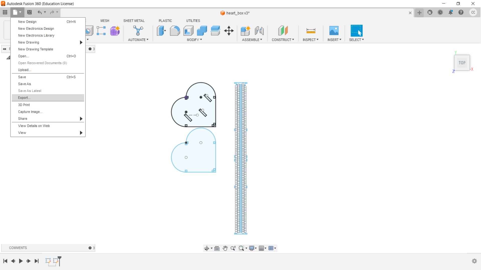
I then exported the dxf file.
Note: Design Corrections
During the cutting process I found that I needed to make a number of corrections, for details see the section called Design Testing and Corrections under the Laser Cutting section on this page.
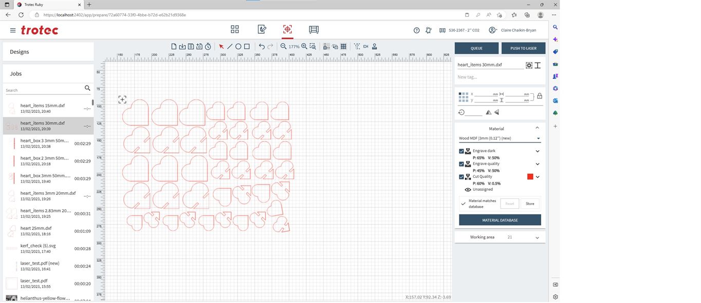
Laser Cutting
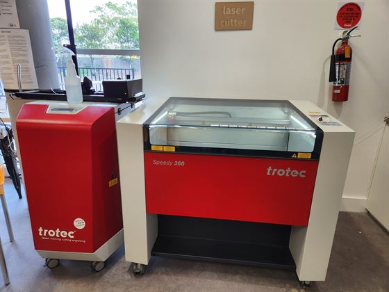
Laser Cutter Model
Model is a Trotec Speedy 360 CO2 80W
Software running the Speedy 360 is Trotec Ruby 2.5.0.29207
Bed size is 800mmx500mm
Laser Cutter Setup
Best settings for MDF 3mm based on testing.
- Speed: 0.5% (50%)
- Power: 60%
- Hz: 1000Hz
Follow the tutorial in Group Work Documentation for details on how to use Ruby on the Trotec Laser cutter to make and send the job to the laser cutter.
Design Testing and Corrections
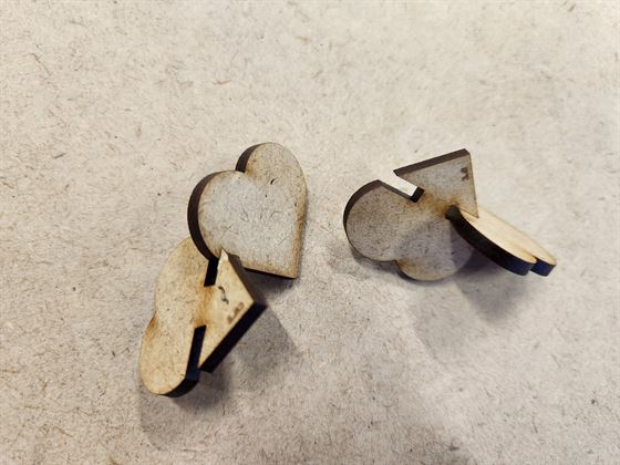
I first decided to test the kerf measurement that was found during group work - 2.83mm against 3mm for a slot and solid piece.
I found that 2.83mm ended up being too small, but 3mm was perfect. I think this is because of the way I have designed the slot on the heart.
I decided to continue with 3mm gaps.
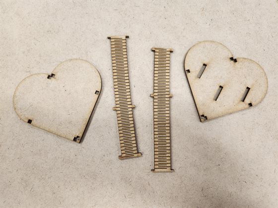
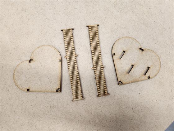
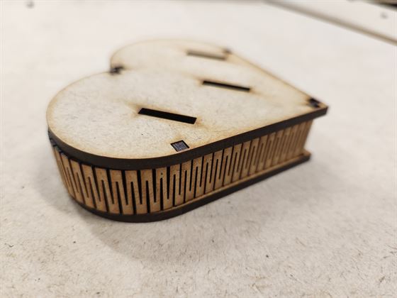
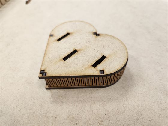
I decided to make the box first.
The top and bottom needed a larger gap between the edge and the cut-outs to connect the side. The bendable side ended up being too long.
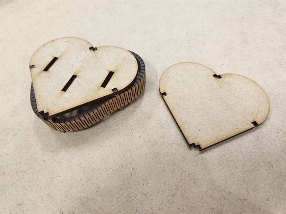
I modified the side to be reduced by 6 x material thickness (18mm when using thickness of 3mm) and divided the side into two so it would not snap when bending into a heart shape. I also added a parametric parameter to set the distance for the top and bottom side connection cut-outs to the edge of the piece.
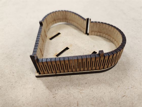
The result worked except the connectors at the base of the heart did not fit, they were set at 3mm wide, they need to be halved to 1.5mm, like those found at the top of the heart.
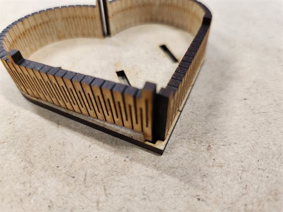
The final result for the box worked and fit snugly together.
For the hearts for people to make their own sculpture on the top of the box I tried a test of the cut using the dxf file made in FreeCAD. However, the laser ran over the cuts multiple times even though it came in as one line for a heart.
I was able to open the FreeCAD dxf in Illustrator and found that there were multiple lines on top of each other. I suspect this is because of the way you make a dxf in FreeCAD using the Parts Design Workbench as the pad is 3D and when reduced to 2D all those lines come with it.
I checked the dxf file made from Fusion 360 and found that it did not do this.
As a result I ended up re-drawing the design in Fusion 360 and using that.
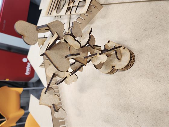
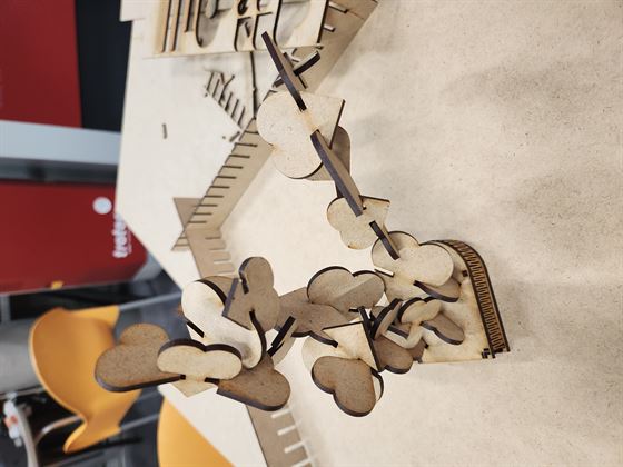
Laser Cut
When the design was all sorted it was time to cut.
Result
Vinyl Cutting
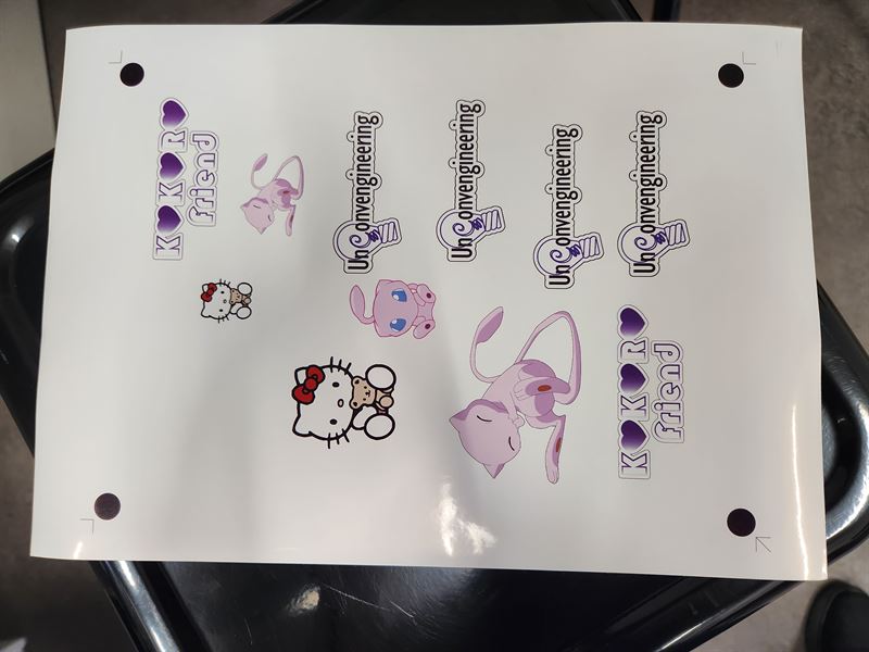
I decided to use my logo design from Week 1 to make my sticker on the vinyl cutter.
![]()
I also decided to use my company logo I designed

As well as a number of free images from the internet of Hello Kitty and my favorite Pokemon, Mew.


*Sources: https://www.pngfind.com/mpng/TihhohJ_mew-chibi-hd-png-download/
https://www.pngfind.com/mpng/Tihhxhb_pokemon-mew-png-transparent-png/
https://www.pngfind.com/mpng/xxmio_hello-kitty-head-png-transparent-png/
https://www.nicepng.com/ourpic/u2a9o0o0r5a9q8r5_free-png-hello-kitty-png-images-transparent-hello/
Vinyl Cutter Model
Roland CAMM-1 GS24
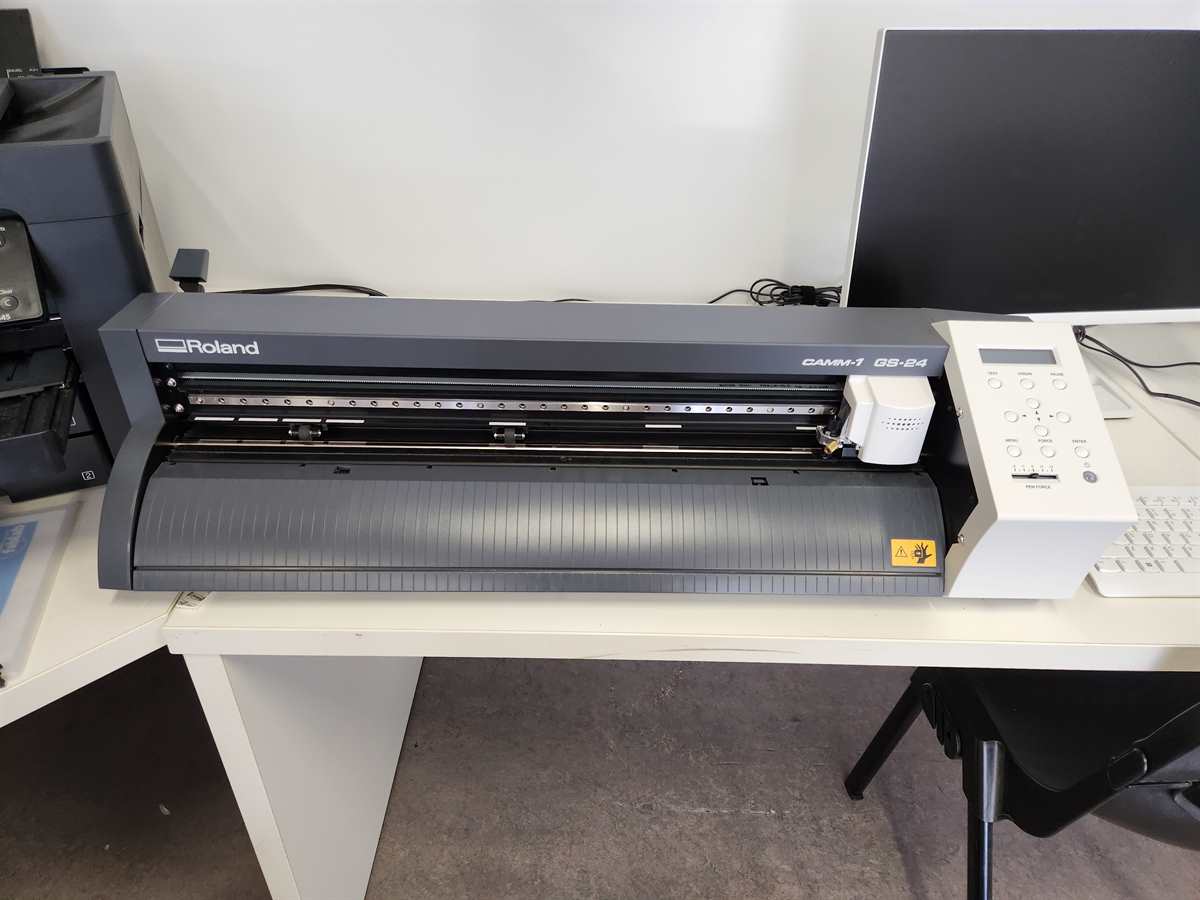
Software Used: Roland CutStudio Version 3.10
Vinyl Cutter Setup, Print and Cut
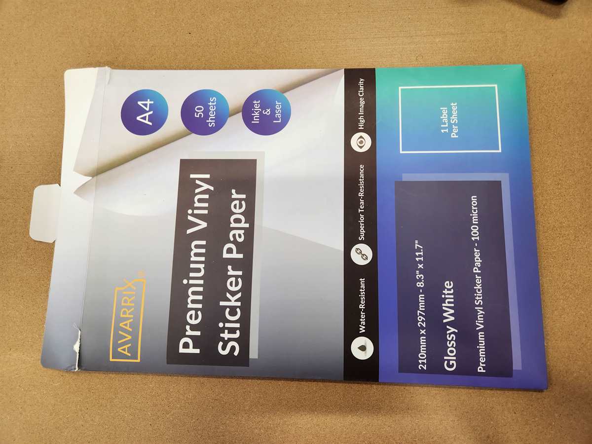
I used printable vinyl sticker paper (A4 Glossy) from Avarrix
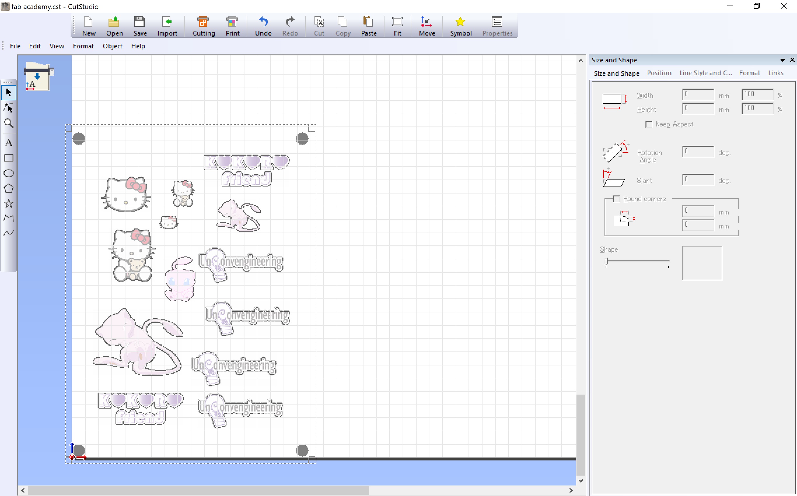
In CutStudio:
- Select Cut and Print
- Setup the cut guides for printing
- Import the images into CutStudio
- Create the cut lines
Print
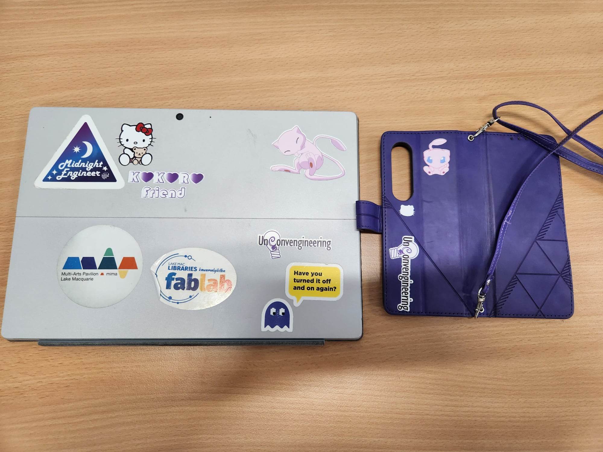
The Hello Kitty head did not print, it appears that the file became corrupted. However the silhouette was still cut out and this actually created a nice effect, you can see it on the phone cover in the photo under Result.
Load
Load the vinyl into the cutter. Make sure that the rollers are on the vinyl and are in a white zone. Make sure to load the vinyl straight and lock the sheet down. Run the loading sequence by selecting piece and then clicking enter.
When the vinyl is loaded move the cutting head over the lower left cutting guide dot (the one with the arrow pointing to it) using the arrow keys on the control panel.
Run Cutting in CutStudio
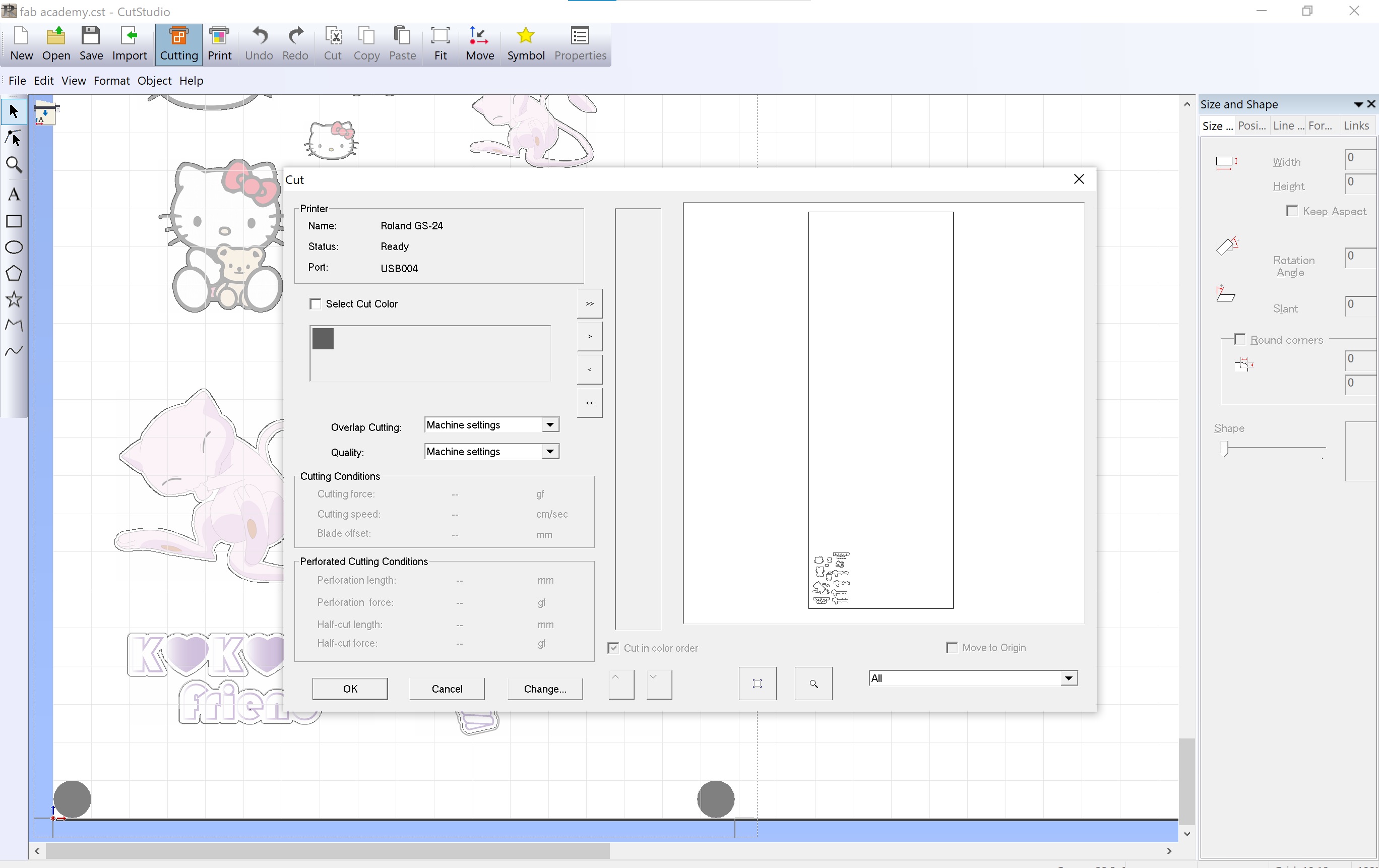
Cut!
Unload
Result
Links to Original Files
Fusion dxf Heart Box
Fusion dxf Heart Items 30mm
Fusion dxf Heart Items 20mm
Fusion dxf Heart Items 15mm
Fusion file Heart Box
Fusion file Heart Items
FreeCAD file Heart Items
FreeCAD dxf Heart Items