Computer controlled cutting
Group Assignment:
-
Characterize your lasercutter’s focus, power, speed, rate, kerf, joint clearance
-
Document your work to the group work page and reflect on your individual page what you learned
Laser Cutting
Principles of laser cutting
Laser cutters are computer-controlled machines that move a laser head in a 2D plane in order to cut through a flat object by physically removing material by burning it away with a laser.
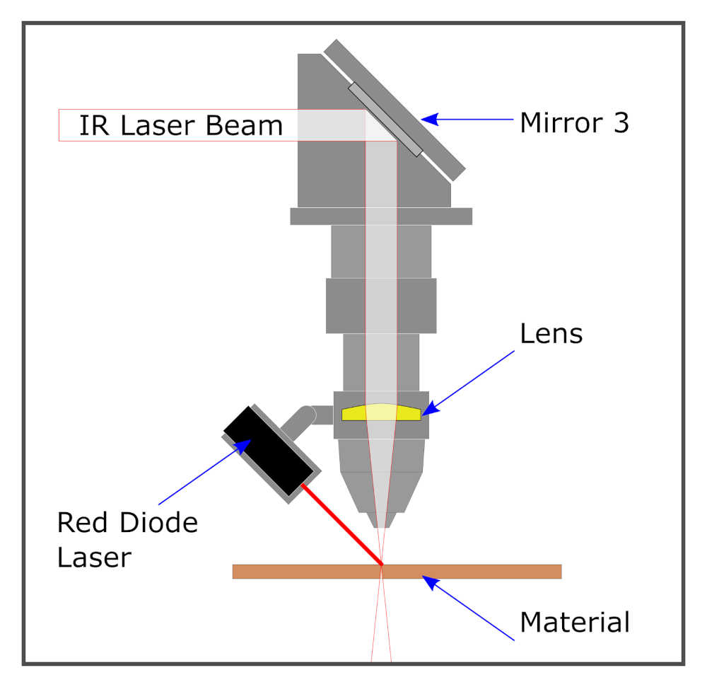
The laser beam itself has a width, however small, that must be accounted for when cutting. As the laser beam cuts through a material, it results in a gap in the material known as “kerf.”
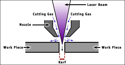
While the laser beam width and shape is fixed, there are many factors that affect the resulting kerf width. Thus, kerf must be determined experimentally and recorded for each different type of material used in the lab along with what settings (namely power and speed) of the laser cutter were used that resulted in that kerf width.
1. Presentation
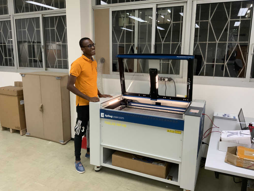
The laser cutter used in the FabLab INP-HB is the **Epilog Laser Edge 36. **
| Specification | |
|---|---|
| Work Area | 36″ x 24″ x 10″ (914 x 610 x 254 mm) |
| Laser Source | CO2 : 80W |
| Speed Control | 0.1-100% (Adjustable) |
| Power Control | 1-100% (Adjustable) |
| Resolution | 75 – 1200 dpi |
| Software | Epilog Dashboard; Inksape |
A complete description of the machine can be found on the manufacturers website
2. Safety
Laser cutter has the potential to burn down the building and cause bodily harm, so please go through the safety instructions thoroughly. The manual can be found here.
The most important safety instructions are copied below from the manual.
Laser cutting safety
- Stay with the laser: Never operate the laser system while unattended.
- Keep the area clear: Clean around the machine and keep the area free of clutter, combustible materials, explosives, or volatile solvents such as acetone, alcohol, or gasoline.
- Be prepared with a fire extinguisher: Always keep a properly maintained and inspected fire extinguisher on hand.
- **Use Air Assist: ** Always use the system’s Air Assist feature when vector cutting.
- Use caution when vector cutting: Many materials have the potential to suddenly burst into flames when cut with a laser – even materials that may be very familiar to the user. Always monitor the machine when it is operating.
- Clean the laser: A buildup of cutting and engraving residue and debris is dangerous and can create a fire hazard in its own right. Keep your laser system clean and free of debris. Regularly remove the Vector Cutting Table to clean any small pieces that have fallen through the grid.
3. Setting focus
In order to engrave or cut a crisp, clean image, your material must be the correct distance
from the bottom of the focus lens. Setting the distance from the bottom of the focus lens
to the top of your material is the process of focusing, and is accomplished by placing your
material on the table and moving the table up or down.
Our laser cutter has auto focus and manual focus functions.
- For the auto focus we have two types:
the auto focus with thickness of the material
For this option, measure the thickness of the material you’re using to engrave or cut, and enter the number in the Thickness box of the Epilog Dashboard software. The table will automatically move up or down so that the top of your material is the right distance from the bottom of the focus lens, just before you start the job.
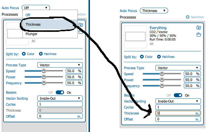
the auto focus with Plunger
When a job is set to the Plunger option, the plunger measures the focus distance at the first point in the job where the laser is fired. The table will automatically move up or down so that the top of your material is the right distance from the bottom of the focusing lens.
- For the manual focus you have two possibilities:
Using the focus gauge supplied with the laser cutter
the manual focus gauge is used to determine the correct distance from the focus lens to the top of your material. Place the object to be cut or engraved anywhere on the machine table. Select the Jog button on the touch screen and use the joystick to move the focus gauge to the object.
Using the auto focus button on the laser cutter’s touch screen
Place the object to be cut or engraved anywhere on the machine table. Select the Jog button on the touch screen and use the joystick to move the focus gauge over the object and click the auto focus button.
For more details please refer to the manual page 123,124.
4. Power and speed
For this part we proceed by the steps
1-The choice of file.
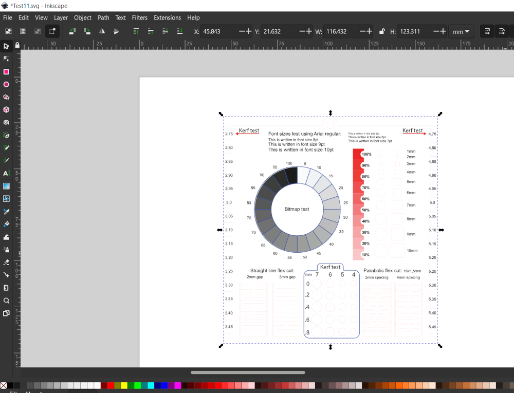 from the Inscape or Gimp software after processing your image
it is now necessary to save it as to have the desired format.
from the Inscape or Gimp software after processing your image
it is now necessary to save it as to have the desired format.
2-The cutting procedure
 Recover the cutting file.
The files taken into account for cutting are as follows: svg, pdf, png ...
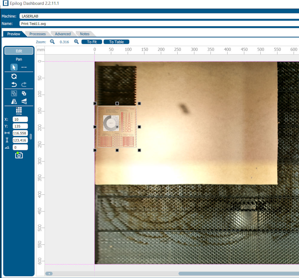
3- Print
for the launch uses the print option and choose
the machine connected to the Computer
the file with the "EpiolgLaser" option
4- Adjusting cutting parameters
First of all, it is necessary to position the material to be cut and then adjust the coordinate to avoid any possible waste or damage to the path during cutting and then close the machin and It is aloso necessary to make the measurements directly on matter
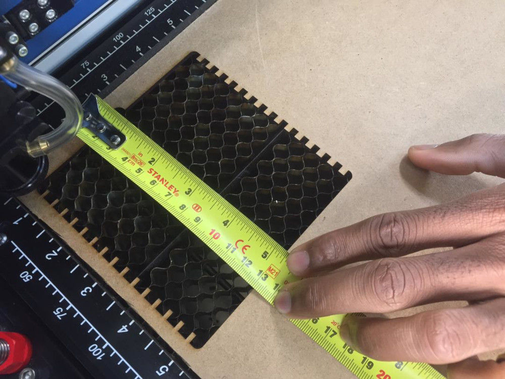 Room placement measurement
- Fundamental parameters We have fixed the value of the power by varying the shade of each image we obtain the quality of engraving and cutting for each value in percentage
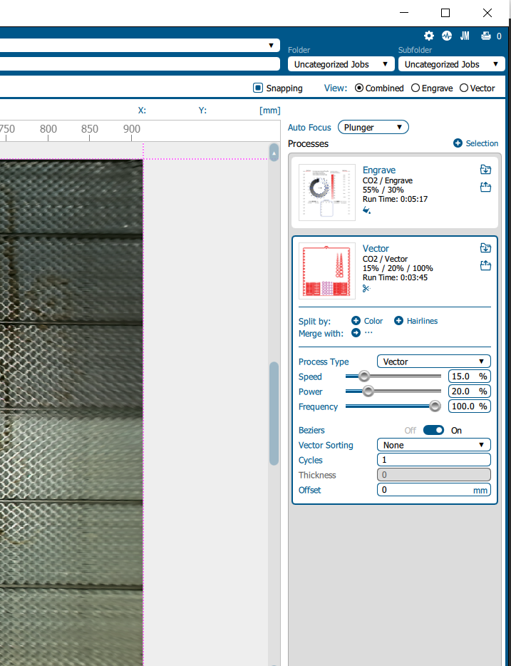 for cutting
the speed :10
the power:20
the frequency:
for engraving
the speed :60
the power:25
resolution : 500
Tthis is parameters are specific to MDF with a thickness of 3 mm. 5- cutting start
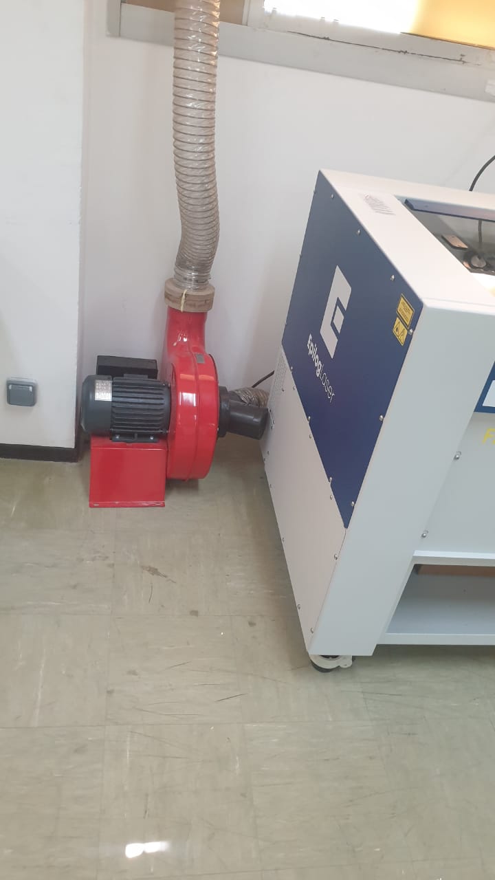
NB: It is necessary to mache the vacuum cleaner. you have to close the machine
Once you have finished with the settings you print and then you go to the machine to launch your part, to be selected the part and click on the start button.
remember the air Starting extractor and compressor.
Let machine do the work!
- cutting Video
- Engraving Video
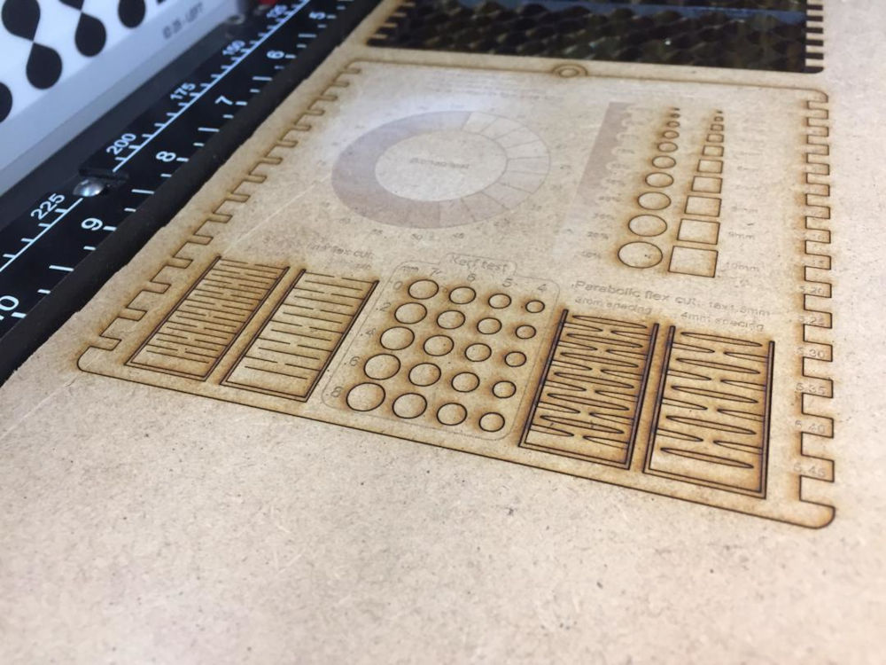
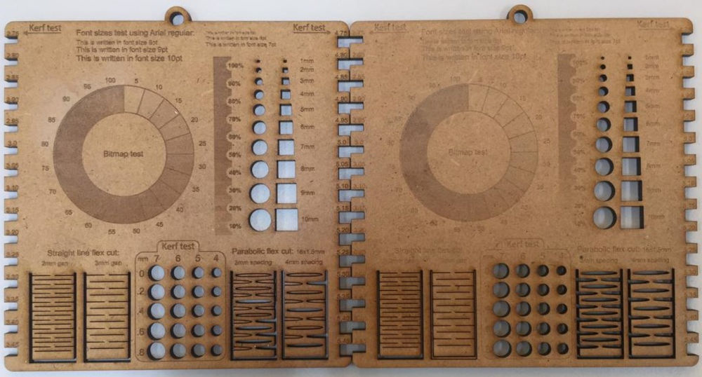
5. kerf
To find the value of the kerf we will make a difference between the value at the beginning and the cut value 4.19 - 4=0.19mm
in other words: the kerf is 0.2mm

–files