Interface and Application Programming
Assignments of the Week
- 1.Compare as many tool options as possible.
- 2.Document your work on the group work page and reflect on your individual page what you learned.
Group assignment:
Individual assignments:
1.Write an application that interfaces a user with input and/or output device(s) on a board that you made.
Group Assignment:
Individual assignments:
1.In Processing, clicking the left and right mouse buttons controls the on and off states of the LED connected to pin 13 (left mouse button opens L RX, right mouse button opens LED RX).
a.Video demonstrating the control of the LED on pin 13 by clicking the left and right mouse buttons.
b.Code
        import processing.serial.*;      //import the library for a serial communication (sketch-import library-serial)

        Serial myPort;                  //define name of the serial communication

        PImage bg;                      //add the background image.Declare variable "bg" of type PImage

        void setup(){                   //we will set a resolution for the graphical window

          size(259, 194);               //set the image size 259 by 194 pixels

          //the image file must be in the data folder of the current sketch to load successfully

          myPort=new Serial(this, "COM33", 9600);  //se the name of our communication port (Arduino COM port)
        }

        void draw(){                    //draw function - here is graphical screen

          background(20,20,20);               //set the background image

          if(mousePressed && (mouseButton == LEFT)){    //get the value of the mouse for the LED turn ON/OFF
            myPort.write('1');          //if pressed the left buton on the screen we will send to the serial port character 1
          }
          if(mousePressed && (mouseButton == RIGHT)){
            myPort.write('0');          //the led turn off
          }
        }
Wiring diagram
I directly used the LED on pin 13 on the UNO without wiring.
Downlod Links
code2. Displaying an image in Processing.
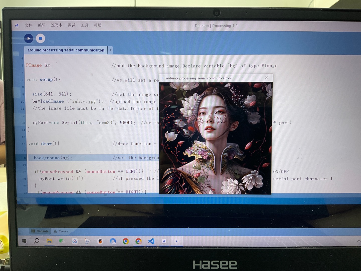
a. Successful image display.
3.Clicking the left and right mouse buttons controls the OLED screen display LEFT and RIGHT connected to pin 5.
a.The video demonstrates controlling the screen display on pin 5 by clicking the left and right mouse buttons.
b.Code
        #include
          #define SCREEN_WIDTH 128  // OLED display width, in pixels
          #define SCREEN_HEIGHT 64  // OLED display height, in pixels
          #define OLED_RESET -1     // Reset pin # (or -1 if sharing Arduino reset pin)
          #define SCREEN_ADDRESS 0x3C
          Adafruit_SSD1306 display(SCREEN_WIDTH, SCREEN_HEIGHT, &Wire, OLED_RESET);

          void setup() {
            Serial.begin(9600);
            Serial.println();
            Serial.println("hello");


          }

          void loop() {
            while (Serial.available()) {
              char c = Serial.read();
              if (c == '0') {
                display.clearDisplay();
                display.setCursor(0, 0);
                display.print("LEFT!");
              } else if (c == '1') {
                display.clearDisplay();
                display.setCursor(0, 0);
                display.print("RIGHT!");
              }
            }

            display.display();
          }
Wiring diagram
You can find my PCB layout diagram in this week's homework. I used the four pins D4\D5\GND\5V.
Downlod Links
code code4.Clicking the left and right mouse buttons controls the buzzer connected to pin 5 to sound and stop sounding.
a.This video demonstrates controlling the buzzer on pin 5 to sound and not sound by clicking the left and right mouse buttons.
b.Code
        void setup() {
          Serial.begin(9600);
          pinMode(D5, OUTPUT);
        }

        void loop() {
          while (Serial.available()) {
            char c = Serial.read();
            if (c == '0') {
              tone(D5, 440);
            } else if (c == '1') {
              noTone(D5);
            }
          }
Wiring diagram
You can find my PCB layout diagram in this week's assignment. I used two pins D5\GND.
Downlod Links
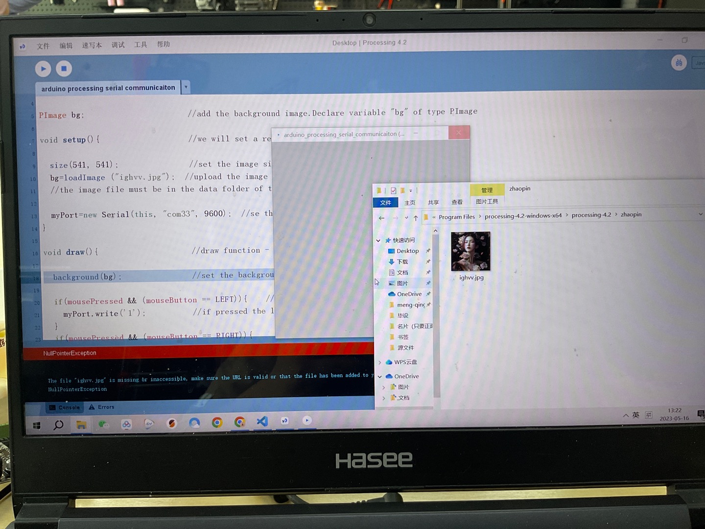
code codeExisting problems
1. Do not create a folder in the root directory to store images, as it will cause Processing to fail to read the images.
2.Read a tutorial in its entirety (including notes, comments, process)