Input Devices
Assignments of the Week
- 1.Probe an input device(s)'s analog and digital signals.
- 2.Document your work on the group work page and reflect on your individual page what you learned
Group assignment:
Group Assignment:
Individual assignments:
1.Measure something: add a sensor to a microcontroller board that you have designed and read it.
Add an output device to the microcontroller board and program it
1. Results video
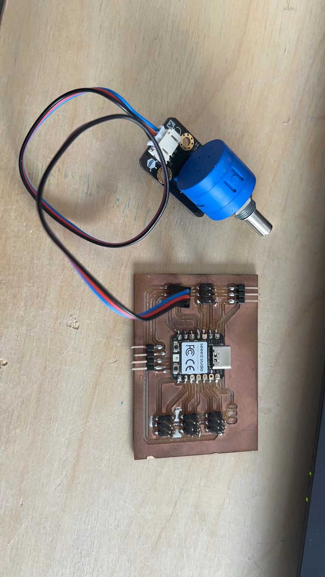
1.1 I used my own PCB to read the resistance value of the potentiometer and display it on the serial monitor.
1.2 Potentiometer introduction
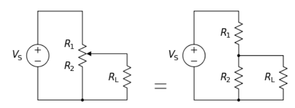
1.3 A potentiometer is a manually adjustable, variable resistor with three terminals. Two terminals are connected to the ends of a resistive element, the third terminal is connected to an adjustable wiper. The position of the wiper sets the resistive divider ratio.
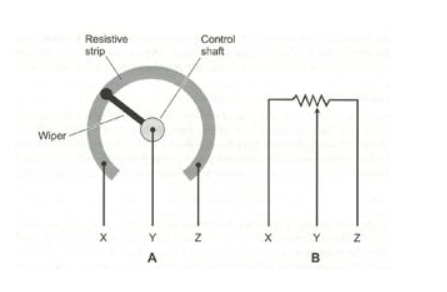
1.3.1 The principle of a potentiometer is that the potential dropped across a segment of a wire of uniform cross-section carrying a constant current is directly proportional to its length. The potentiometer is a simple device used to measure the electrical potentials (or compare the e.m.f of a cell). One form of potentiometer is a uniform high-resistance wire attached to an insulating support, marked with a linear measuring scale. In use, an adjustable regulated voltage source E, of greater magnitude than the potential to be measured, is connected across the wire so as to pass a steady current through it.A potentiometer has three connecting terminals. Two terminals are the fixed ends of the resistor, through which the current flows when powered. The third connection point is the variable contact point, which is connected to one of the fixed ends of the resistor through a knob or sliding arm.
1.3.2 Potentiometers are widely used in electronic circuits to adjust the voltage, current, or signal magnitude within the circuit. For example, they can be used as volume controllers, dimmer switches, temperature regulators, and more.
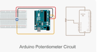
1.4 Wiring diagram
1.4.1 A Potentiometer, also known as a variable resistor, is a component used to adjust the resistance value. It is typically adjusted using a knob or a sliding arm.
1.4.2 A potentiometer has three connecting terminals. Two terminals are the fixed ends of the resistor, through which the current flows when powered. The third connection point is the variable contact point, which is connected to one of the fixed ends of the resistor through a knob or sliding arm.
1.4.3 Potentiometers are widely used in electronic circuits to adjust the voltage, current, or signal magnitude within the circuit. For example, they can be used as volume controllers, dimmer switches, temperature regulators, and more.
1.4.4 connecting questions
You can find my PCB layout diagram in this week's homework. I used the four pins D4\D5\GND\5V.
1.5 Coding
          int sensorValue = 0;

          void setup() {
          Serial.begin(9600);
          }

          void loop() {
          sensorValue = analogRead(A0);
          Serial.println(sensorValue);
          delay(100);
          }
1.6 Downlod Links
Potentiometer code2. Shock sensor
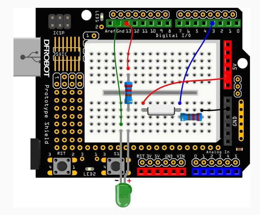
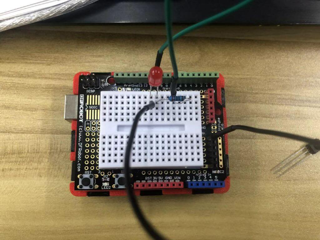
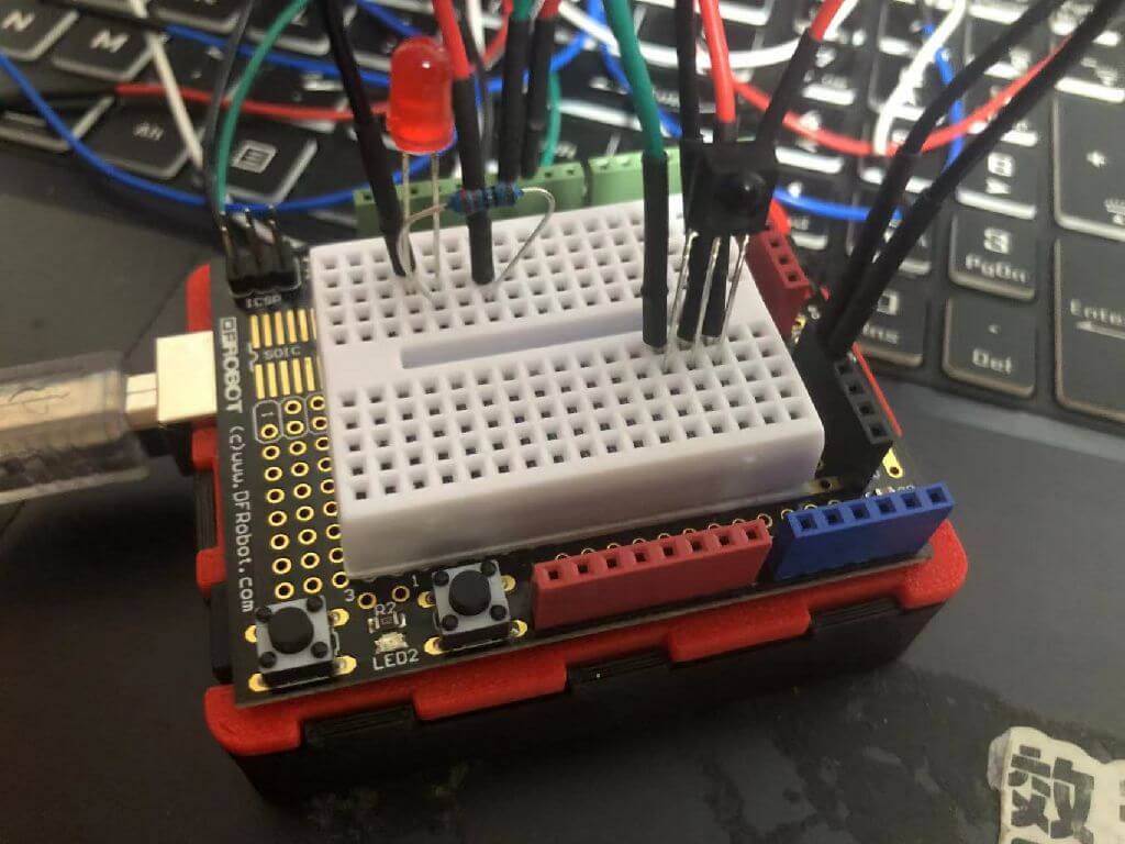
2.1 Wiring diagram
2.2 achievement
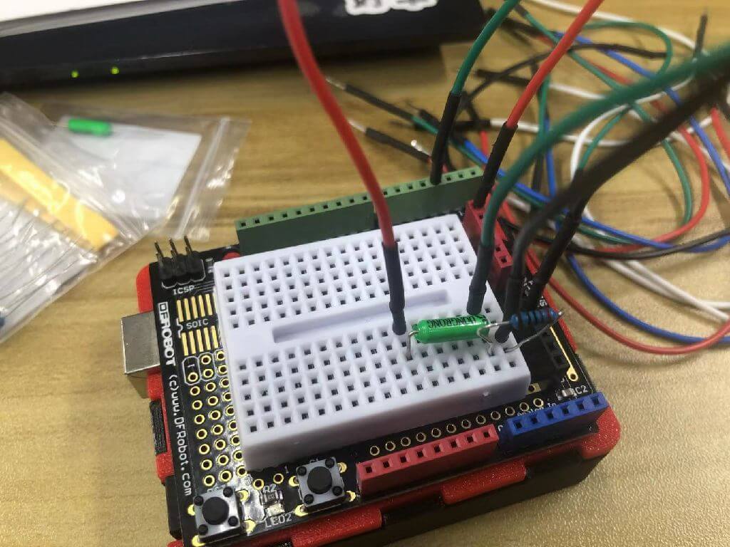
2.3 Install the vibration sensor
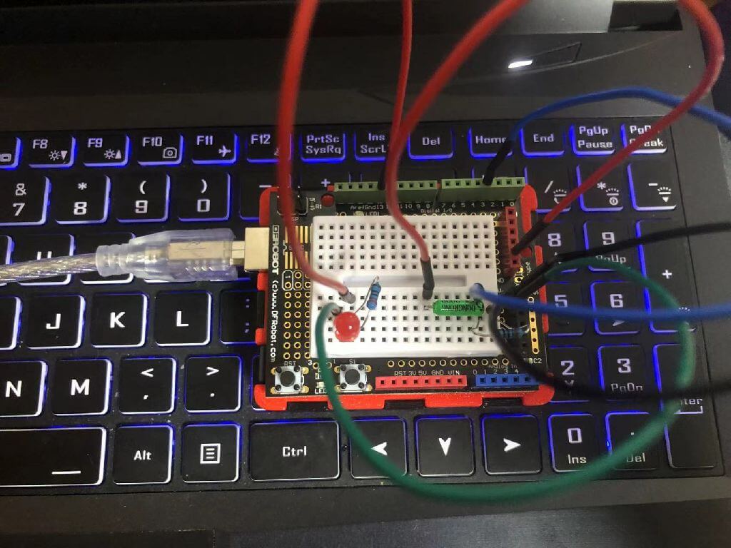
2.4 Install the red LED
2.5 The Code
            int SensorLED = 13;       //Define LED as digital pin 13
            int SensorINPUT = 3;      //Connect the vibration switch to interrupt 1, which is digital pin 3
            unsigned char state = 0;

            void setup() {
              pinMode(SensorLED, OUTPUT);         //LED is in output mode
              pinMode(SensorINPUT, INPUT);        //Vibration switch is input mode

              //In the process of changing from low level to high level, interrupt 1 is triggered and the blink function is called.
              attachInterrupt(1, blink, RISING);
             }

            void loop(){
                  if(state!=0){              // If state is not 0
                    state = 0;               // The state value is assigned to 0
                    digitalWrite(SensorLED,HIGH);   // Turn on the light
                    delay(500);          //Delay 500ms
                  }
                  else
                    digitalWrite(SensorLED,LOW);     // Otherwise, turn off the lights
            }

            void blink(){                //Interrupt function blink()
            state++;             //Once the interrupt is triggered, state will continue to increase.
            }
         }
3.Infrared remote control
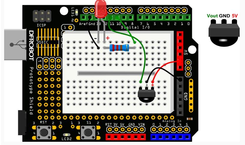
3.1 Wiring diagram
3.2 achievement
3.3 Install the red LED
3.4 Install the infrared remote control
3.5 The Code
              #include
                int RECV_PIN = 11;
                int ledPin = 10;                // LED – digital 10
                boolean ledState = LOW;         // ledstate is used to store the status of LEDs
                IRrecv irrecv(RECV_PIN);
                decode_results results;

                void setup(){
                    Serial.begin(9600);
                    irrecv.enableIRIn();
                    pinMode(ledPin,OUTPUT);       // Set LED to output state
                }

                void loop() {
                     if (irrecv.decode(&results)) {
                             Serial.println(results.value, HEX);

                             //Once the code of the power button is received, the LED flips state, HIGH changes to LOW, or LOW changes to HIGH
                        if(results.value == 0xFD00FF){
                                ledState = !ledState;
                                digitalWrite(ledPin,ledState);    //Change LED corresponding status
                           }
                           irrecv.resume();
                       }
                }
                }