9.Output Devices
Assignments of the Week
- 1.Measure the power consumption of an output device.
- 2.Document your work on the group work page and reflect on your individual page what you learned.
Group assignment:
Group Assignment:
Individual assignments:
1.Add an output device to a microcontroller board you've designed and program it to do something.
Add an output device to the microcontroller board and program it
1. Connect the screen and display Meng on the screen.
1.1 Code
       #include
         #include
         #include
         #include

         #define SCREEN_WIDTH 128
         #define SCREEN_HEIGHT 64

         #define OLED_RESET     4
         Adafruit_SSD1306 display(SCREEN_WIDTH, SCREEN_HEIGHT, &Wire, OLED_RESET);

         void setup() {
         Serial.begin(9600);
         display.begin(SSD1306_SWITCHCAPVCC,0x3C);
         }

         void loop() {
         display.clearDisplay();
         display.setTextSize(1.5);
         display.setTextColor(meng);
         display.setCursor(10,10);
       }
1.2Downlod Links
code1.3 Code analysis
1.3.1 The following code is for importing library files.
      #include
        #include
        #include
        #include
1.3.2 The following code sets the dimensions (width and height) of the OLED screen in pixels.
      #define SCREEN_WIDTH 128
      #define SCREEN_HEIGHT 64
1.3.3 The following code is for customizing the reset pin, which is necessary when using the Adafruit_SSD1306 library.
         #define OLED_RESET     4
         Adafruit_SSD1306 display(SCREEN_WIDTH, SCREEN_HEIGHT, &Wire, OLED_RESET);
1.3.4 The following code opens serial communication, initializes the OLED screen, and sets its I2C address to 0x3C.
      Serial.begin(9600);
      display.begin(SSD1306_SWITCHCAPVCC,0x3C);
1.3.5 The following code involves using common parameters for an OLED screen.
      // Clear display buffer
      display.clearDisplay();
      //Set font size
      display.setTextSize(1.5);
      //Set the displayed text
      display.setTextColor(meng);
      //Set cursor position
      display.setCursor(10,10);
1.4 connecting questions
You can find my PCB layout diagram in this week's homework. I used the four pins D4\D5\GND\5V.
Since my own PCB was used to create my final project, I used the UNO board in the supplementary assignment below.
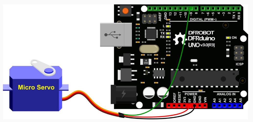
2. I use the UNO board to control the SG90 servo to rotate from 0 degrees to 180 degrees, and then from 180 degrees back to 0 degrees. The rotation angle each time is 45 degrees.
2.1 Code
        #include
          Servo myservo; //Create a servo object to control the servo

          int pos = 0;//The pos variable is used to store the servo position
          int pin = 9;//The pin variable is used to select the pin that controls the servo motor. Only pwm pins can be used. In Arduino UNO the pwm pins are 3, 5, 6, 9, 10 and 11.

          void setup() {
            myservo.attach(pin);//Connect the servo to the servo object on pin 9
          }

          void loop() {
            for (pos = 0; pos <= 180; pos += 45)//Gradually rotate from 0 degrees to 180 degrees, rotating 45 degree in the positive direction each time
            {
              myservo.write(pos);//Tell the servo to go to the position represented by the variable 'pos'
              delay(500);//Wait 500 milliseconds for the servo to reach the target position
            }
            for (pos = 180; pos >= 0; pos -= 45)//Gradually rotate from 0 degrees to 180 degrees, turning 1 degree in the negative direction each time
            {
              myservo.write(pos);//Tell the servo to go to the position represented by the variable 'pos'
              delay(500);//Wait 500 milliseconds for the servo to reach the target position
            }
          }
        }
2.2 Downlod Links
code2.2 Wiring diagram
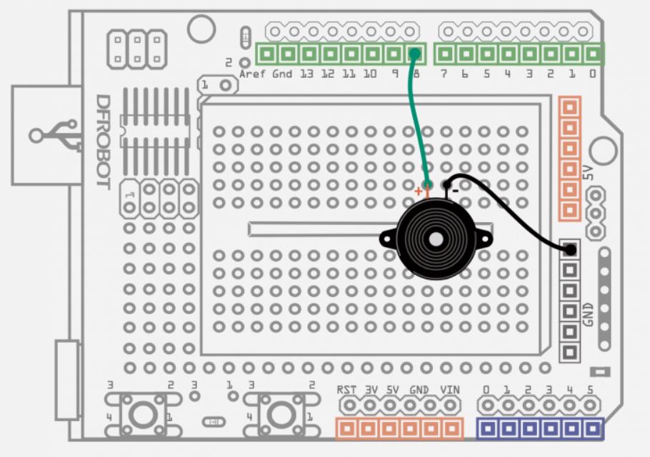
3. I'm using a UNO board to control a buzzer to sound the alarm.
3.1 Code
            float sinVal;//Set floating point variable
            int toneVal;//Set integer variable

            void setup(){
                 pinMode(8, OUTPUT);
            }

            void loop(){
                 for(int x=0; x<180; x++){

                        sinVal = (sin(x*(3.1412/180))); //Convert sin function angle to radians
                        toneVal = 2000+(int(sinVal*1000)); //Use the sin function value to generate the frequency of the sound
                        tone(8, toneVal); //Give pin 8 a variable
                        delay(2);
                 }
            }
3.2 Downlod Links
code3.3 Wiring diagram
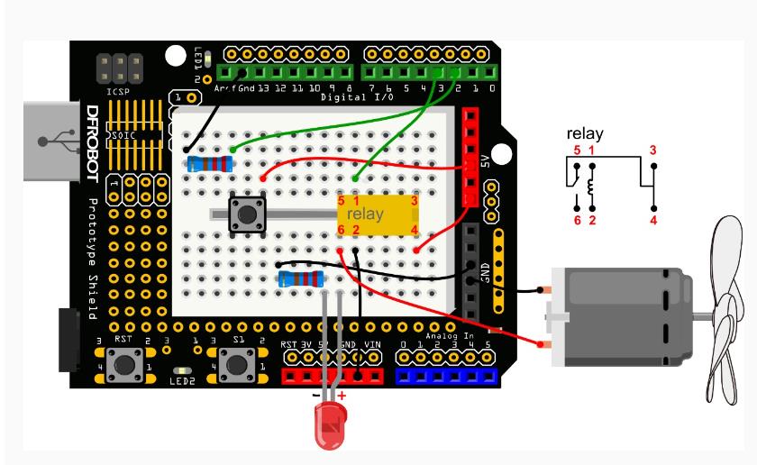
4. DC motor
4.1 Wiring diagram
4.2 video
4.3 Install Button
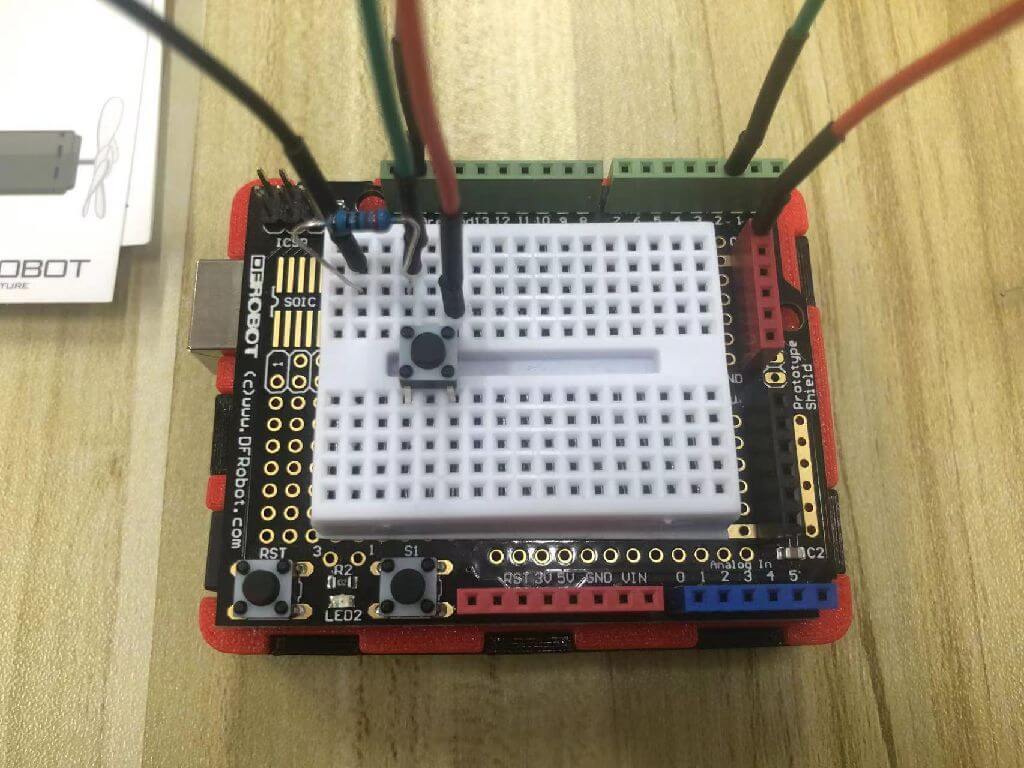
4.3.1 Connect the 220R resistor.
4.3.2 Connect the resistor end to digital pin 2.
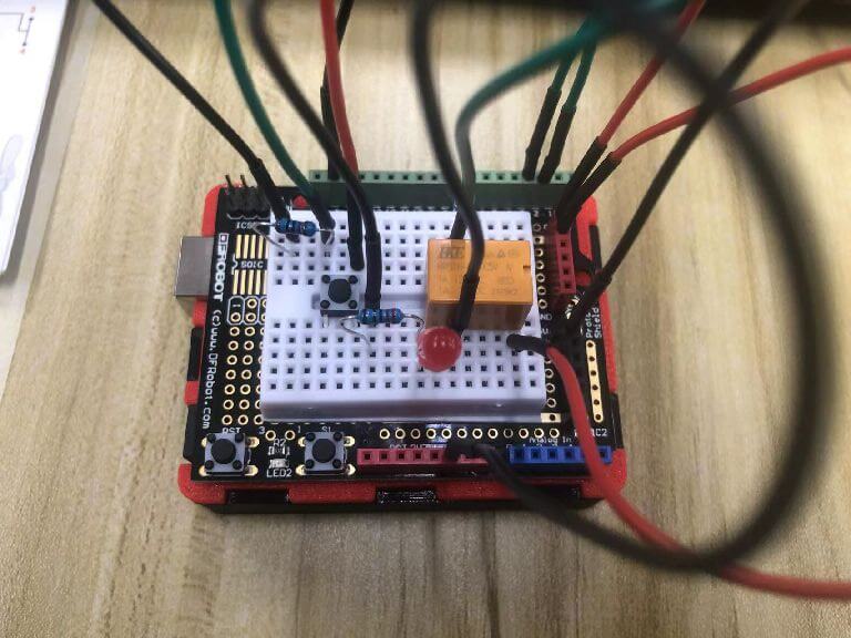
4.4 Install the small relay and red LED
4.4.1 Relay pin 1 is connected to digital pin 3.
4.4.2 Connect pin 2 of the relay to GND.
4.4.3 The positive pole of the LED is connected to pin 6 of the relay, the negative pole is connected to a 220R resistor and then connected to GND.
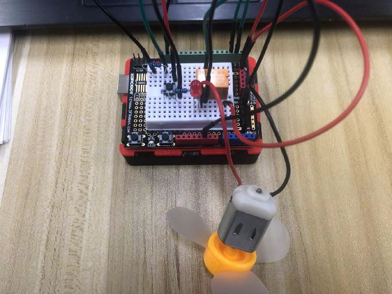
4.5 install fan
4.5.1 The positive pole (red wire) of the fan is connected to pin 6 of the relay.
4.5.2 The negative pole (black wire) of the fan is connected to GND.
4.6 The Code
              int buttonPin = 2;                          // button connected to number 2
              int relayPin = 3;                           // Relay connected to number 3
              int relayState = HIGH;                      // The initial state of the relay is HIGH
              int buttonState;                            // Record the current state value of the button
              int lastButtonState = LOW;                  // Record the previous state value of the button
              long lastDebounceTime = 0;
              long debounceDelay = 10;

              void setup() {
                     pinMode(buttonPin, INPUT);
                     pinMode(relayPin, OUTPUT);

                     digitalWrite(relayPin, relayState);  // Set the initial state of the relay
              }

              void loop() {
                     int reading = digitalRead(buttonPin); //reading is used to store the data of buttonPin
                     // Once a change in data is detected, the current time is recorded
                     if (reading != lastButtonState) {
                                 lastDebounceTime = millis();
                      }
                      // Wait 50ms and make another judgment to see if it is the same as the current button state.
                      // If it is different from the current state, change the button state
                      // At the same time, if the button state is high (that is, it is pressed), then change the state of the relay
                     if ((millis() - lastDebounceTime) > debounceDelay) {
                            if (reading != buttonState) {
                                    buttonState = reading;

                                     if (buttonState == HIGH) {
                                               relayState = !relayState;
                                     }
                             }
                       }
                       //Change the previous state value of the button
                       digitalWrite(relayPin, relayState);
                       lastButtonState = reading;
              }