
For this week's assignment, we were tasked with building a machine that incorporates mechanism, actuation, automation, and application. Our selected project was an automatic painting machine, which we designed to post-process 3D printed parts.
Video N°1
The first step in our design process was to create a displacement axis that could handle painting large pieces. To achieve this, we designed a plate that could raise and lower the spray can, inspired by the "Urumbu" design, which has a semi-cut section that adapts to the metal profile.
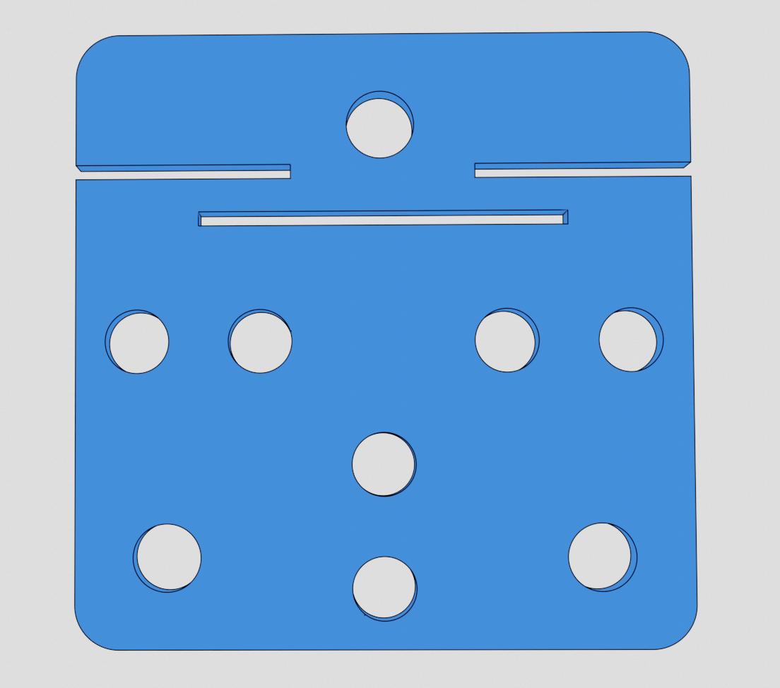
Figure N°1
We used a Nema 17 stepper motor to move the plate via a pulley.
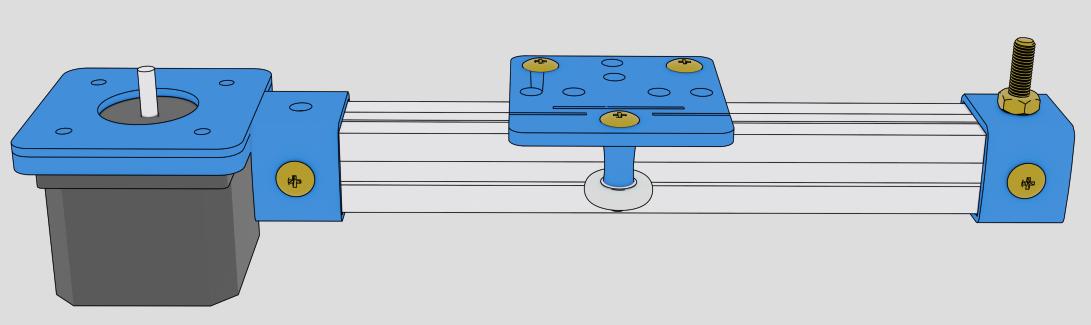
Figure N°2
The 3D printed parts were made with PLA filament on a Flashforge Guider 2.
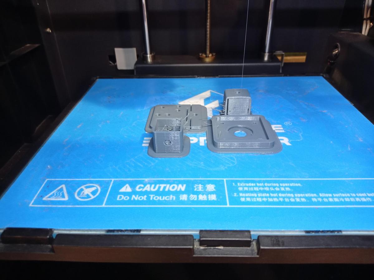
Figure N°3
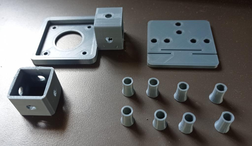
Figure N°4
When we assembled all the pieces, we discovered that the axis could be manually moved horizontally. However, when we tested the axis with a load on top, the weight caused the bearings to sink and come out of the metal profile.
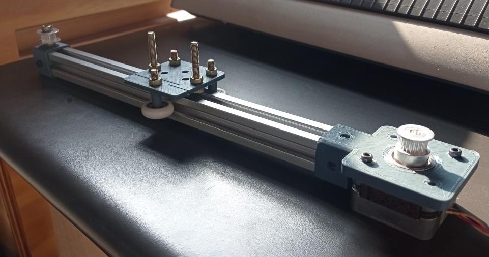
Figure N°5
To solve this issue, we modified the mechanism by adding another plate on the other side and using a longer bolt. With this change, the bearings were not deflected and remained within the profile even when under a load.
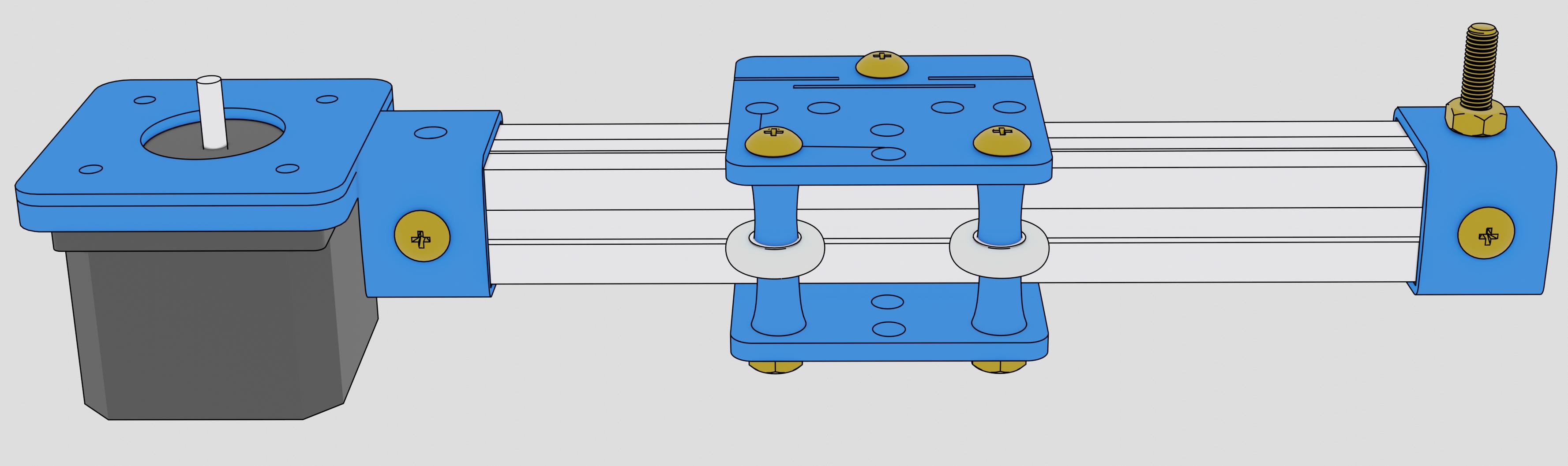
Figure N°6
To activate the spray paint, we made a mechanism using an MG996R servo motor, which has enough torque to press the can. We added an adjustment section with a bolt to prevent the mechanism from moving.
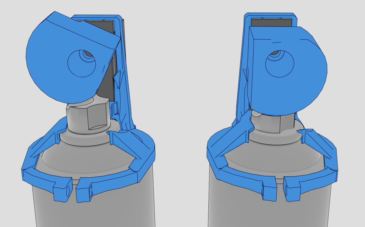
Figure N°7
The 3D printed mechanism had some imperfections due to an error when printing with an ABS temperature for PLA.
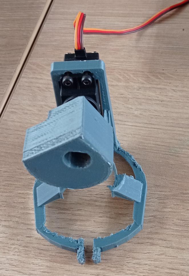
Figure N°8
To hold the piece and rotate it during painting, we used another Nema 17 stepper motor with a 3D printed adapter and a plate made of MDF, which was manufactured with a laser cutter.
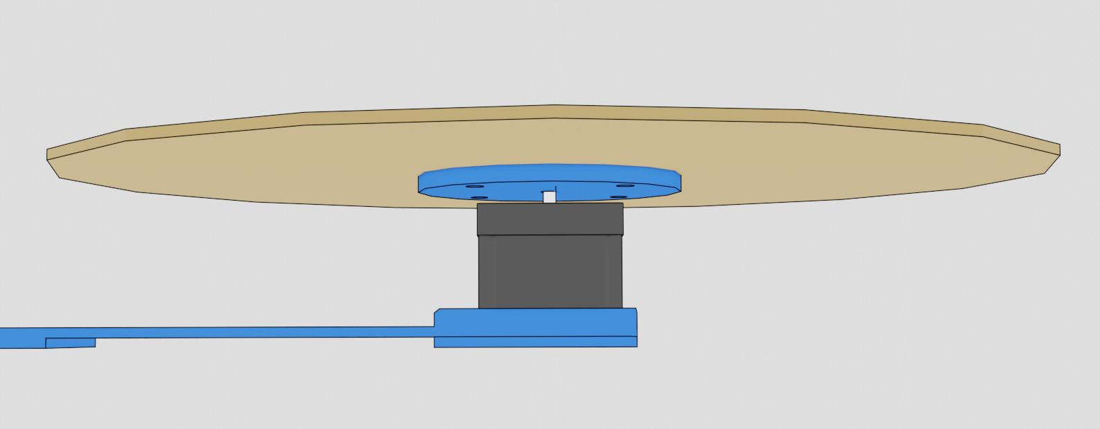
Figure N°9
We attached this platform using bolts and connected it to the 3D printed adapter that held the stepper motor.
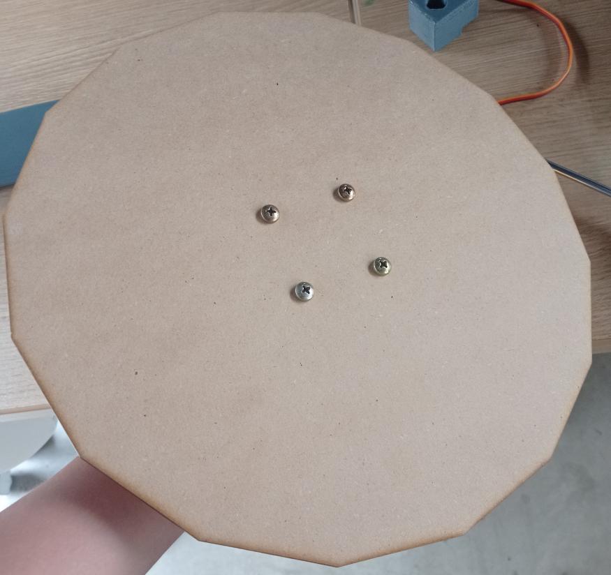
Figure N°10
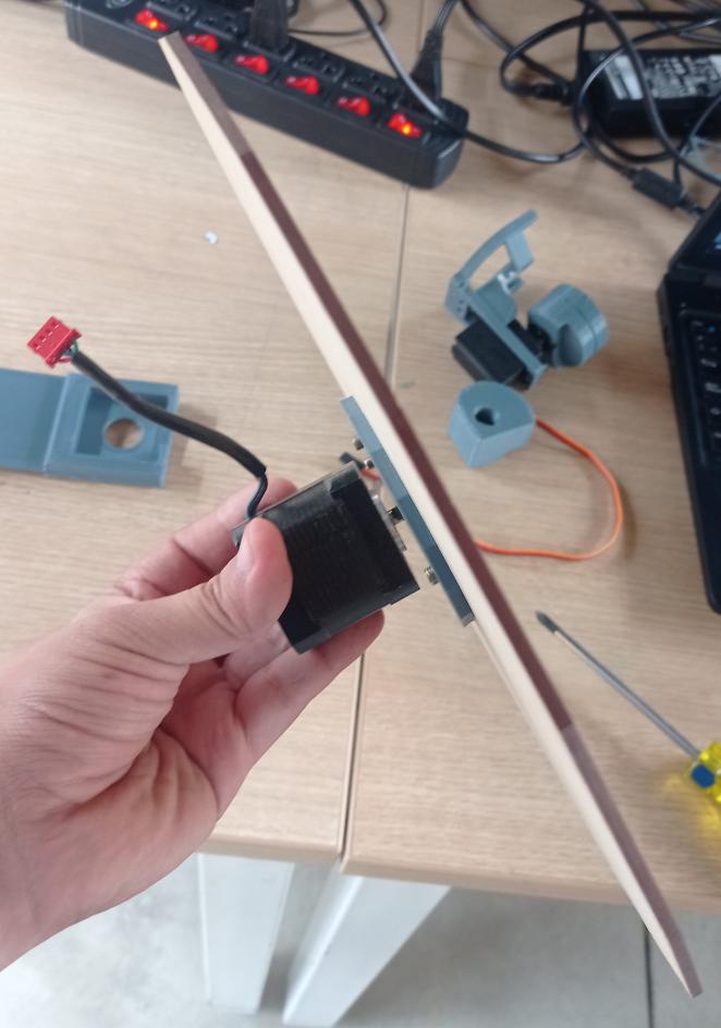
Figure N°11
This is a render of the implementation of two axes of the machine. We combined it with the platform and the activation mechanism with the servomotor, as seen here.
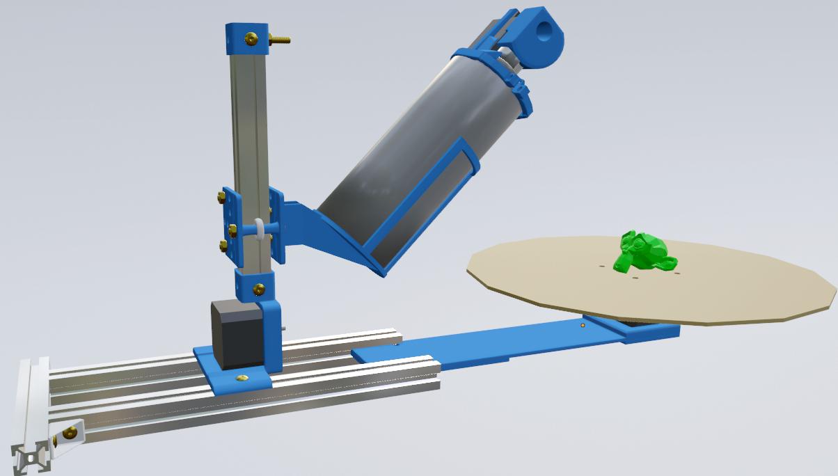
Figure N°12
The final model was rendered in Blender
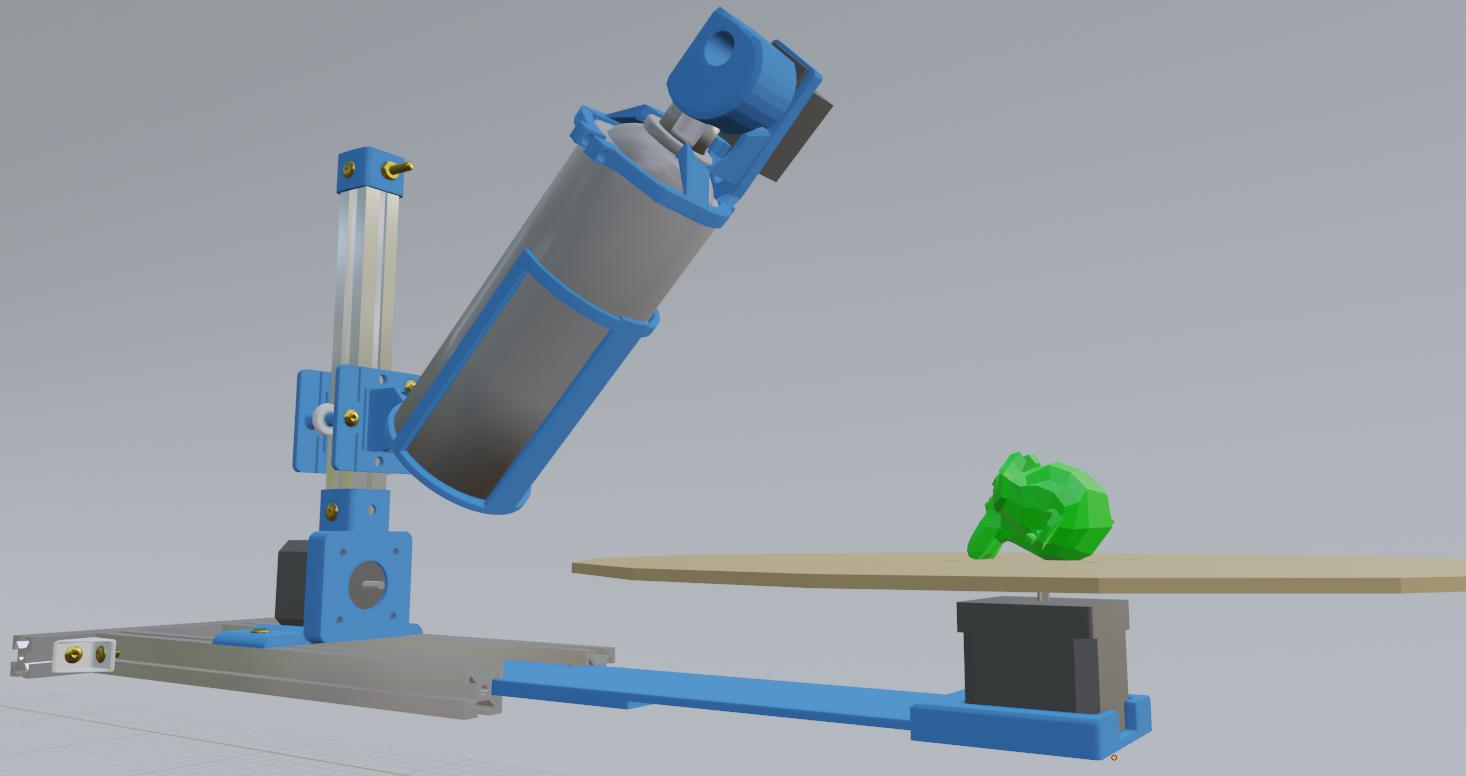
Figure N°13
This was the implementation of two axes of the machine.
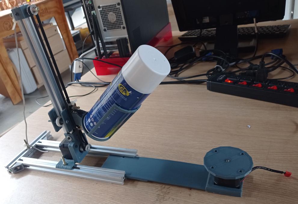
Figure N°14
We combined it with the platform and the activation mechanism with the servomotor, as seen here.
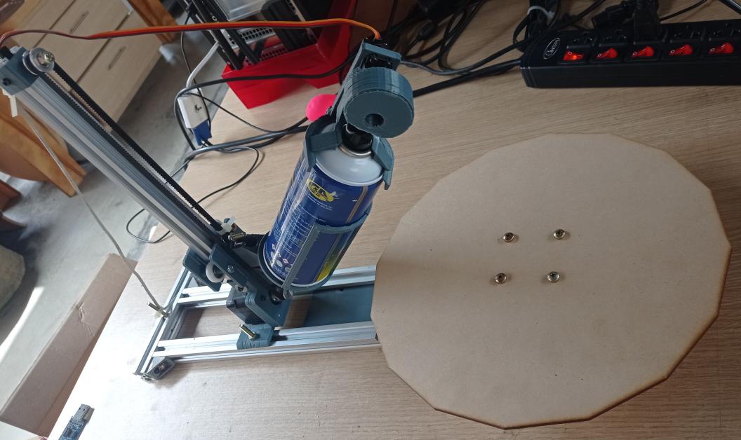
Figure N°15
To control the machine, we developed a printed circuit board using KiCad.
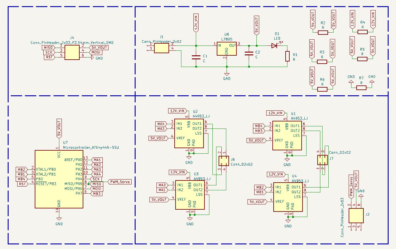
Figure N°16
The board had separate components for the central unit, power system, programming pins, and power modules. We made it a single layer and used several 0 ohm resistors as jumpers.
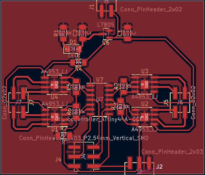
Figure N°17
3D model of the printed circuit board.
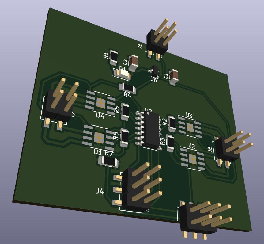
Figure N°18
This board was built using a Roland CNC router.
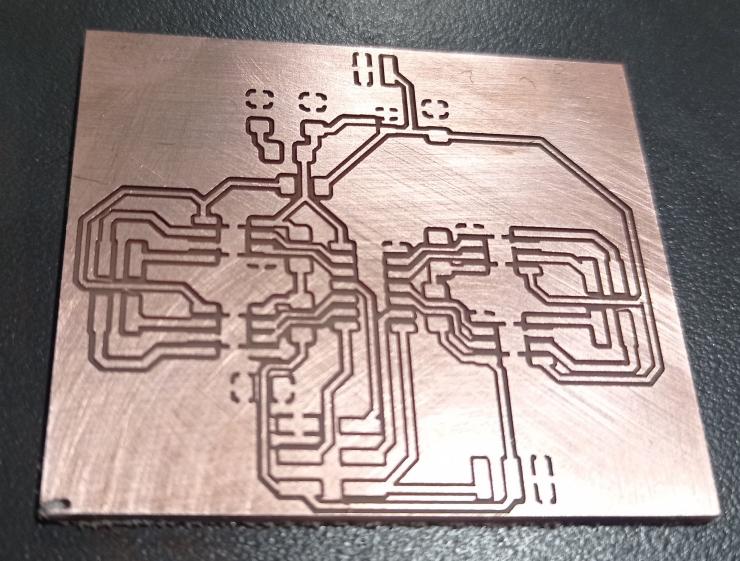
Figure N°19
We gave it a flux bath to make soldering easier, and the components were properly welded.
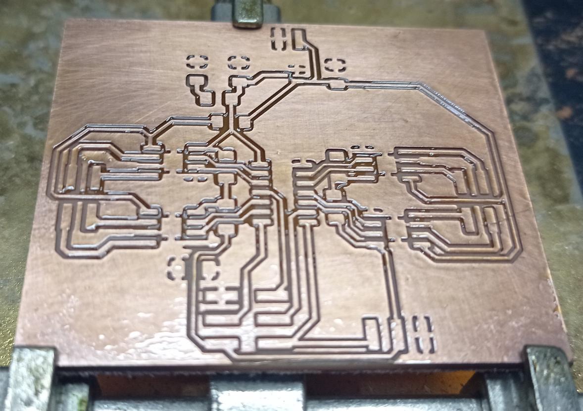
Figure N°20
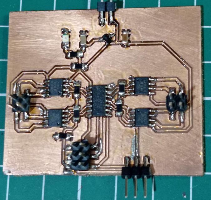
Figure N°21
We added programming pins according to the ISP protocol, which we carried out with a USBAsp programmer module.
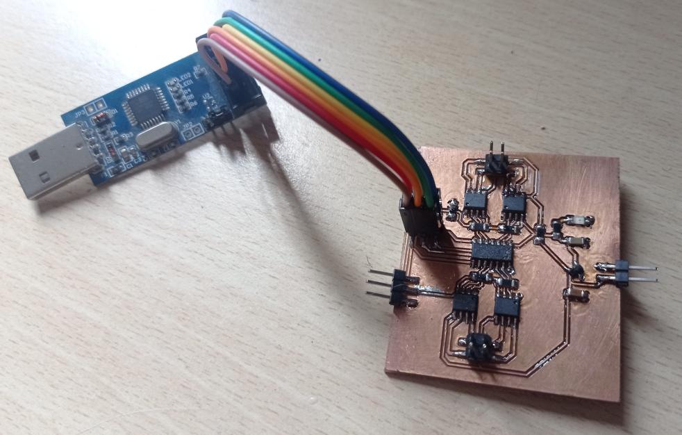
Figure N°22
Test of the axis that rotates the plate without any load, having an adequate performance.
Video N°2
Vertical axis displacement without the spray can, adequate performance.
Video N°3
Displacement of the vertical axis with the spray can, in this we see that certain steps are lost and the speed changes slightly.
Video N°4
First version of the activation mechanism with the servomotor, in this we see that although it achieves a proper first activation, on the second attempt it makes the nozzle move to one side causing a jam.
Video N°5
In the second version of the mechanism, a section was added to hold the position of the nozzle, with this it no longer rotates and the direction of the painting is maintained.
Video N°6
The section that supports the motor that moves the platform can be adjusted to change the distance between the spray and the part.
Video N°7
When a test was made joining the rotation of the platform and the servomotor it got stuck and the part intermittently tried to return without success.
Video N°8
With this problem, an evaluation of the current consumed by the 2 stepping motors was made, in the previous tests there was a 12 volt and 1 amp power supply, in this test a stationary power supply with a capacity of 3.2 amps was used. , we can observe the consumption of each axis is excessive and by not having the necessary current, jams are generated.
Video N°9
Due to this problem, it was decided to change the power system, in this test using 2 L298N modules, this change made the performance of the machine optimal.
Video N°10
Tests were made joining the 2 stepper motors and the servomotor simultaneously with a large vase, having an adequate performance.
Video N°11
We can see a final test painting a regular size piece. The machine works!
Video N°12
The files created or used this week can be downloaded here:
| 3D printed parts | Link |
| PCB Kicad Files | Link |
| PCB SVG files | Link |
| Arduino Script | Link |
| Lasercut plate | Link |