
This week the assigned task is the configuration, and use of different cutting machines.
The first machine that we will use is a laser cutter; in our laboratory, we have a Trotec Speedy 400 model; its characteristics are the following:
| Laser power | 25-75 watts for the CO2 laser |
| Work area | 1000 x 610 mm |
| Maximum height of the piece admitted | 296mm |
| Maximum engraving speed | 355cm/sec |
Table N°1
The material that will be used for all the tests related to the laser cutter are MDF sheets, which is a medium density fiberboard. The plates had a thickness of 3mm
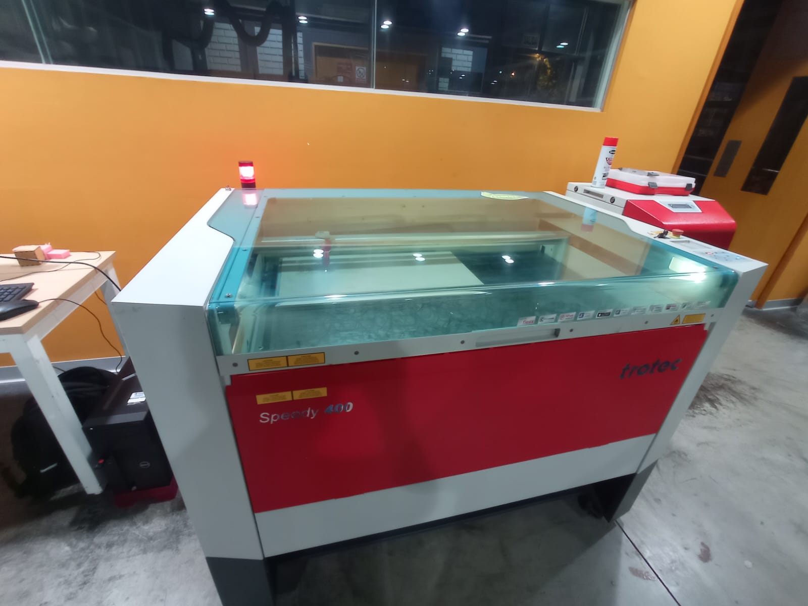
Figure N°1
To start using this machine, it is necessary to calibrate the distance between the laser and the platform; when it is turned on, it starts from the lowest part, and the user must locate the platform with the manual location buttons; for this a piece of calibration (Figure No. 2)
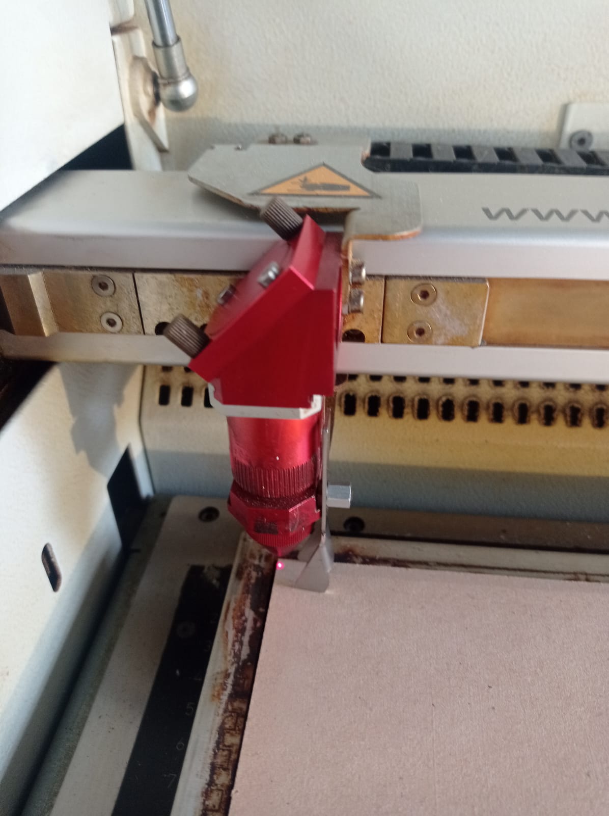
Figure N°2
The software for this task will be Corel Draw; here, with the basic tools, we were able to create a test matrix; here, we vary the power and speed values to find the optimal point. Within the interface, we can locate the work's position concerning the scene's origin. Different colors are used within the vectors, which will be associated with different power and speed values.

Figure N°3
In our first piece, several errors were found, mainly because it was not verified that there is a relationship between the colors of the design with the assigned parameters; 3 values of this matrix were not carried out for this reason.
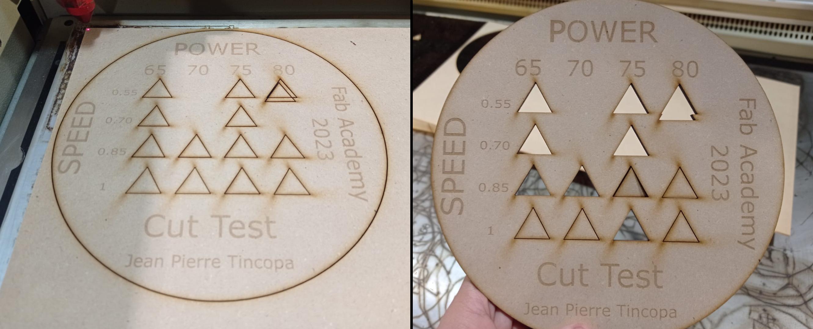
Figure N°4
To correctly assign these colors, the dropper function was used concerning the color options within the Trotec JobControl program so that it recognizes them when sent by Corel Draw.

Figure N°5
In this software, we can locate the design to be cut for the current position of the laser pointer, assign the powers and speeds according to color and calculate the time it will take per color.
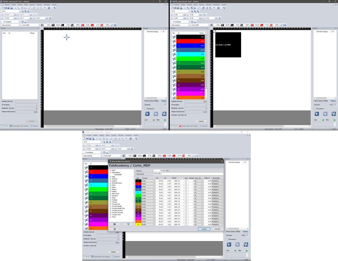
Figure N°6
Knowing now what is the correct way to assign power and speed values, several matrices were made.
| __ Cut Test #1 __ | 65 | 70 | 75 | 80 |
| 0.55 | △ | △ | △ | △ |
| 0.70 | △ | △ | △ | △ |
| 0.85 | △ | △ | △ | △ |
| 1.00 | △ | △ | △ | △ |
Table N°2
| __ Cut Test #2 __ | 85 | 90 | 95 | 100 |
| 2 | △ | △ | △ | △ |
| 3 | △ | △ | △ | △ |
| 4 | △ | △ | △ | △ |
| 5 | △ | △ | △ | △ |
Table N°3
| __ Engrave Test #1 __ | 50 | 55 | 60 | 65 |
| 65 | △ | △ | △ | △ |
| 70 | △ | △ | △ | △ |
| 75 | △ | △ | △ | △ |
| 80 | △ | △ | △ | △ |
Table N°4
| __ Engrave Test #2 __ | 50 | 55 | 60 | 65 |
| 85 | △ | △ | △ | △ |
| 90 | △ | △ | △ | △ |
| 95 | △ | △ | △ | △ |
| 100 | △ | △ | △ | △ |
Table N°5
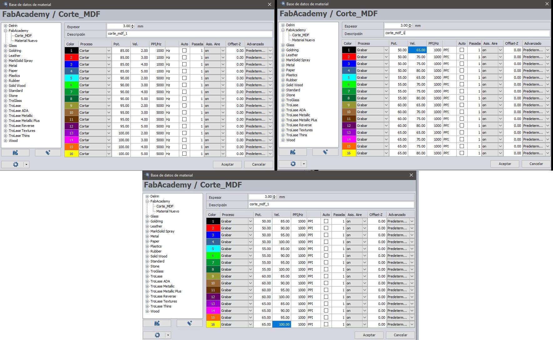
Figure N°7
In Figure No.8 We can see the result of both tests..
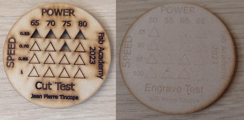
Figure N°8
With this, table No. 6 was formed
| __ Cut Results __ | |
| Power | 65 - 80 |
| Speed | 0.55 |
| __ Engrave Results __ | |
| Power | 50 - 65 |
| Speed | 85 - 95 |
Table N°6
The next step is to find the kerf; for this, a design was made using Fusion 360, here through a Sketch positioning ourselves from the upper point of view. We increase and decrease 0.03mm in this design on the same axis.
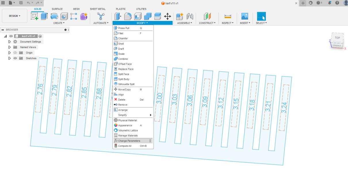
Figure N°9.1
We will do this using parametric design, in this software we have the option to create and modify parameters, this is found in the "modify" --> "Change parameters" section.
Figure N°9.2
In this screen we add a "user parameter" where we determine the name of the variable, the unit and the amount.
Figure N°9.3
In a design there can be more than one parameter.
Figure N°9.4
Within the design we use the same terms that we previously saved so that they change dynamically when we make any changes.

Figure N°9.5
We can see in figure No that the engraving that the text was too small and, therefore, cannot be seen in the resulting piece. After this, a piece was created to determine the relative error with a vernier.
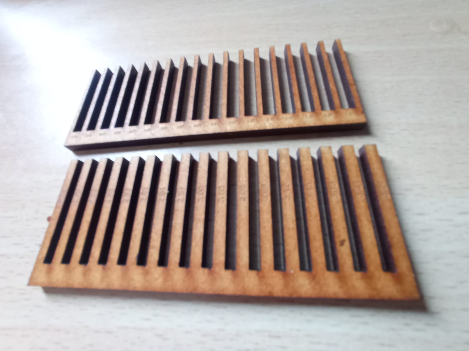
Figure N°10
With this, table No. 7 was formed, where the relative error between the theoretical design and the result can be seen, as well as the general error as an average of these values.
| Real - | Theoretical | - Kerf |
| 2.76 | 2.37 | 0.39 |
| 2.79 | 2.52 | 0.26 |
| 2.82 | 2.49 | 0.33 |
| 2.85 | 2.51 | 0.34 |
| 2.88 | 2.55 | 0.33 |
| 2.91 | 2.64 | 0.27 |
| 2.94 | 2.62 | 0.32 |
| 2.97 | 2.66 | 0.31 |
| 3.00 | 2.67 | 0.33 |
| 3.03 | 2.72 | 0.31 |
| 3.06 | 2.76 | 0.30 |
| 3.09 | 2.78 | 0.31 |
| 3.12 | 2.85 | 0.27 |
| 3.15 | 2.87 | 0.28 |
| 3.18 | 2.92 | 0.26 |
| 3.21 | 2.97 | 0.24 |
| 3.24 | 2.93 | 0.31 |
The average kerf was 0.303. This will be the value that we will use in the individual assignment.
Fusion 360 was used again for the individual task; this time, we will create nestable pieces to form different figures; the joints between these pieces will be subject to variations due to the thickness of the material added to the previously obtained kerf. Then the proposed design will have variables established in the program as user parameters.

Figure N°11
Once the user parameters have been established, we can expose the design so that it can be read by Corel Draw, which is why the.DXF format was chosen.

Figure N°12
Using the values obtained in the grou assignment, we proceeded to cut the nestable pieces.
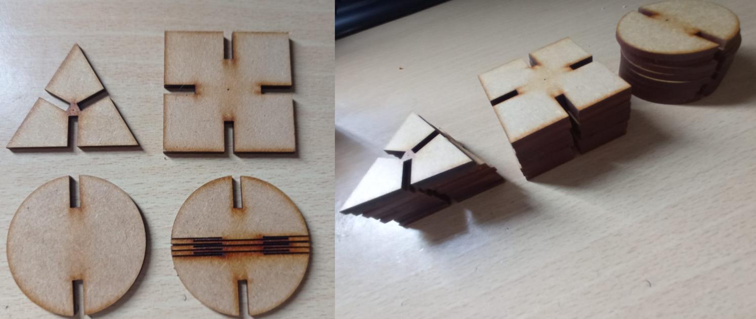
Figure N°13
It is essential to mention that changes were made in the fourth piece of the design that was intended to be flexible; the first values of 0.5mm thickness ended up breaking very quickly, and the optimal value found was 0.1mm, as can be seen in Figure No. 14
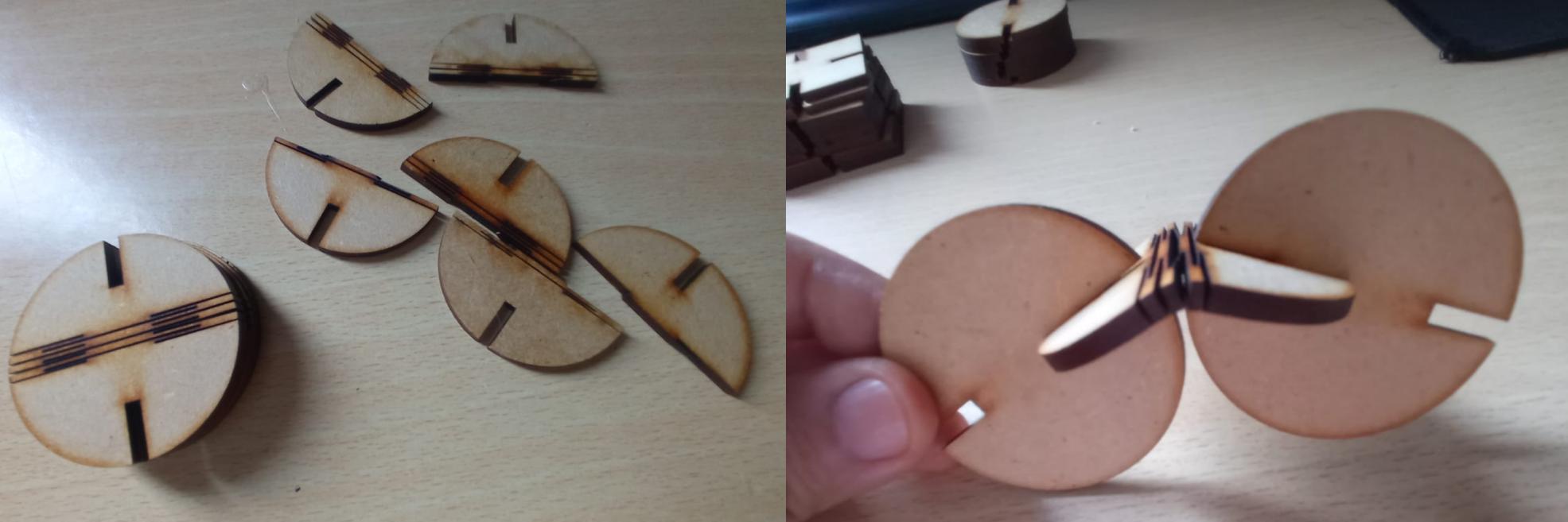
Figure N°14
The result of mixing the first 3 pieces can be seen in Figure No. 15

Figure N°15
In Figure No. 16 We can see the design of a crane joining all the pieces, including the flexible one.
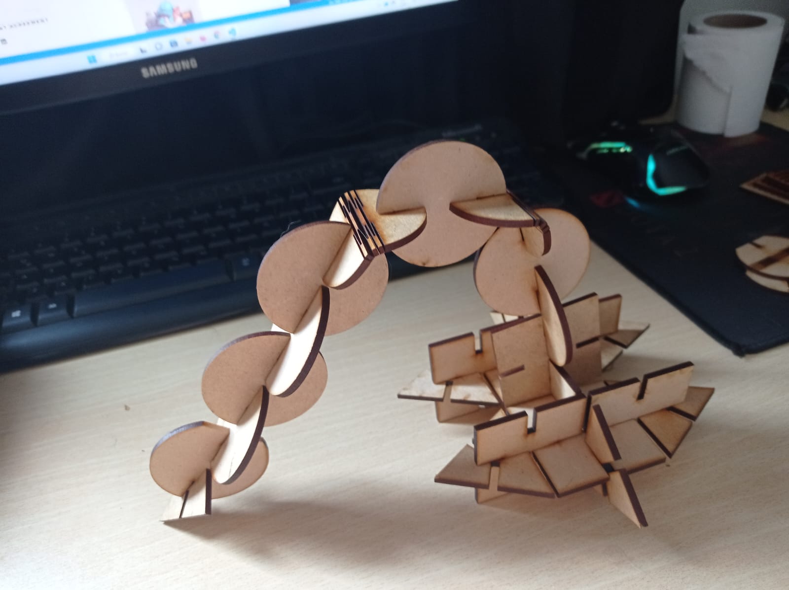
Figure N°16
Moving on to the next experiment, we will use a vinyl cutting machine; the brand is Roland and the CAMM-1Servo model; the characteristics are as follows
| Width of the material to be loaded | From 50 to 700mm |
| Maximum cutting area | Width: 584mm Length: 25m |
| Cutting speed | From 10 to 500mm/sec |
| Blade pressure | From 30 to 250gf |
Table N°7
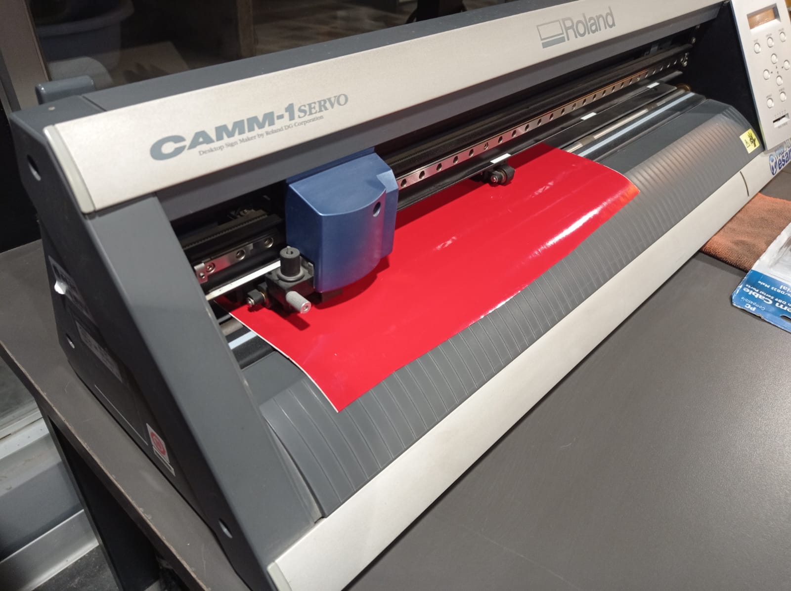
Figure N°17
The first step is to secure the vinyl roll in the machine; it has different positions to secure it according to the width of the roll.
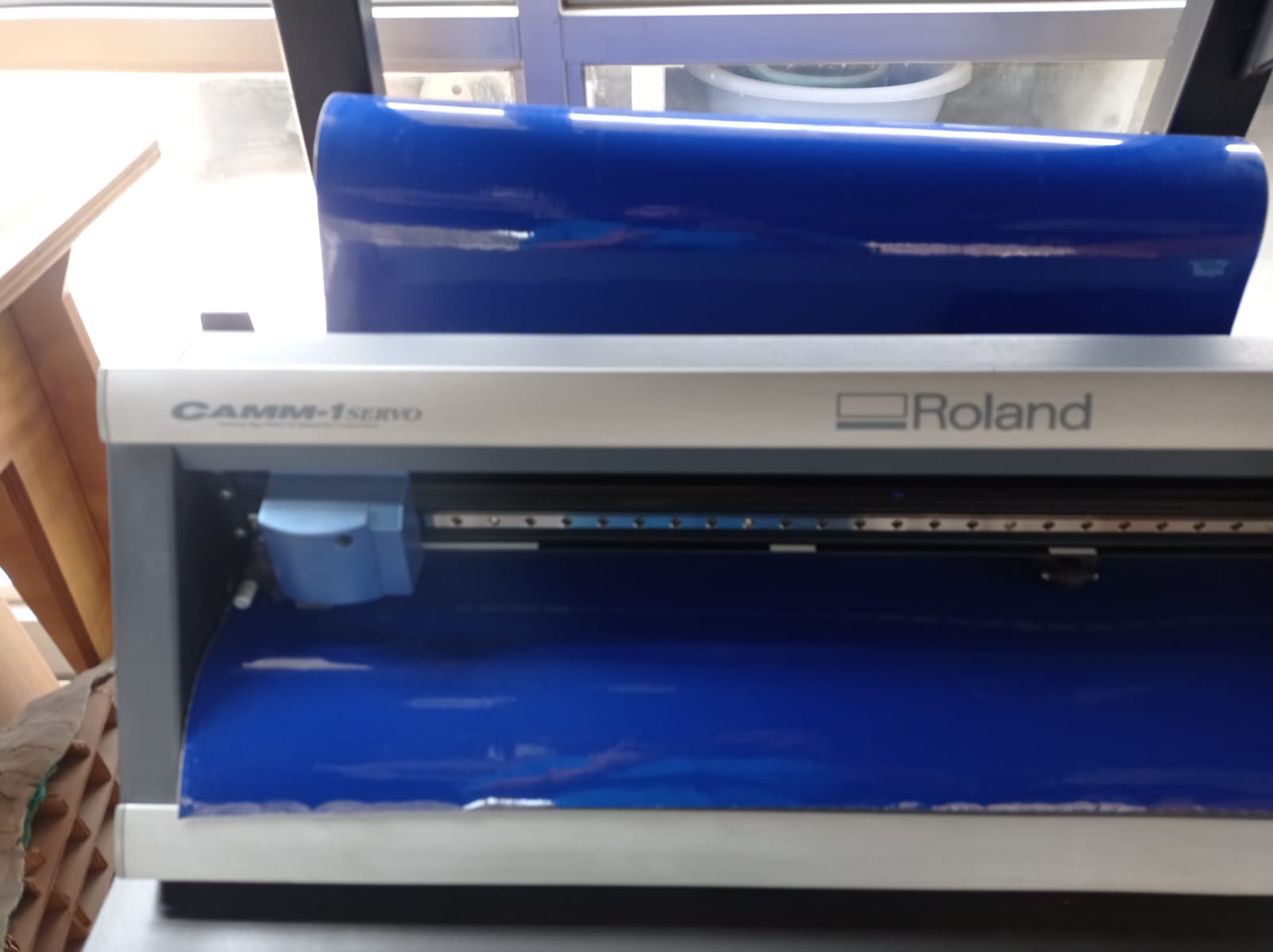
Figure N°18
The software used to control this machine is Fab Modules from a Linux Mint computer. In this program, you choose the image format and the machine you want to control. When the file is imported, "make a path" must be displayed, where the path that the cutting blade will travel will be displayed
This software allows us to change the parameters in the third section of the screen (Figure N°19), among them we have the force with which the blade presses on the material, the speed that depends on what material we are working with, in some such as the copper it is advisable to have a low speed, in this case the material is a common vinyl so we will maintain the standard speed and the origin, in some cases to avoid wasting material we can start in the middle of one that was previously cut so that it starts to cut from that point.
For this experiment, an force of 120 gf and a speed of 5cm/s was setting.
The 2D design that we will use for this example is the one that was made in week 2 and can be downloaded here.

Figure N°19
The display of the machine shows the parameters established in Figure No. 20
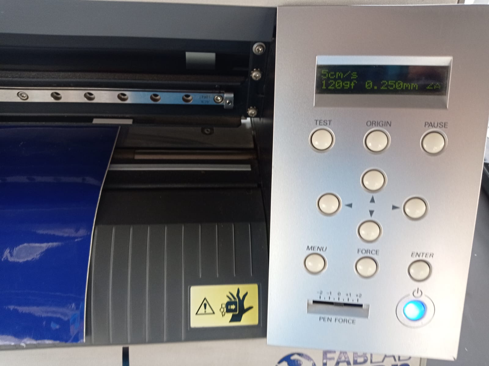
Figure N°20
Having cut the vinyl, we proceed to remove all the excess with a tweezer, leaving only the parts of the design.

Figure N°21
In order to transfer this vinyl, masking tape is used to remove it from the default material and then place it on the final surface where you want to stick it.
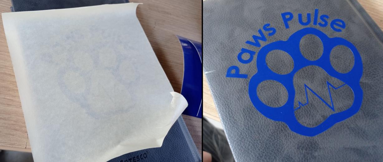
Figure N°22
The files created and used this week can be downloaded here:
| Cut Test #1 | Link |
| Cut Test #2 | Link |
| Engrave Test #1 | Link |
| Engrave Test #2 | Link |
| Kerf | Link |
| buildable parts | Link |
| Paw Pulse Logo | Link |