
This week the objective is to make use of different 2D and 3D design programs, test them, experiment and compare the advantages of each one.
The software I used is Inkscape. Which allows us to manipulate figure or do Boolean operations to join or subtract them and form vector paths.
The first exercise we will do is create logos for our final project. The first one will be called MeowMonitor since it will monitor a cat's food consumption. For this we start with elliptical figures to form the body and head, some triangles for the ears, and some rectangles for the legs. (Figure No. 1)

Figure N°1: Basic forms
To form the cat's belly, we will use another elliptical figure to make a Boolean subtraction, as well as for the leg, the same operation will be used. (Figure No. 2)
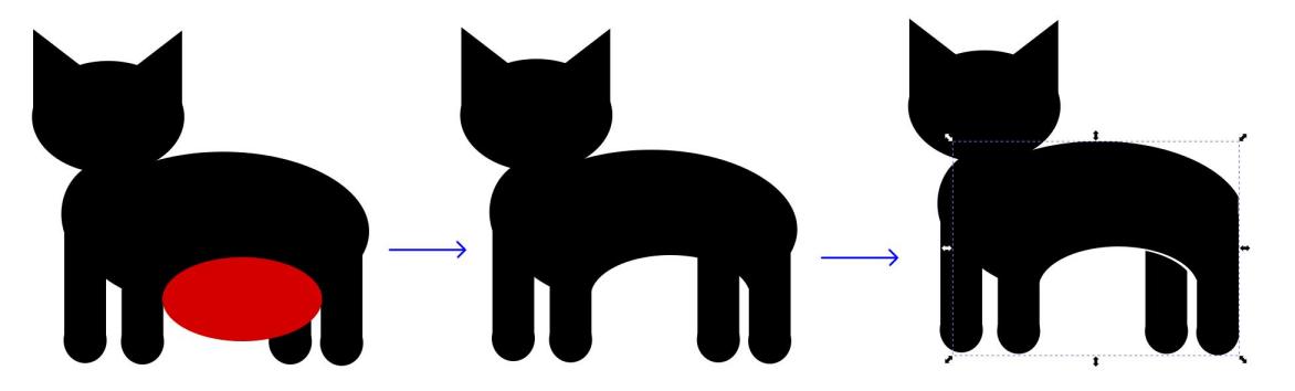
Figure N°2: Operations between figures
We repeat the same for each eye, for the mouth we use 4 ellipses to subtract 2 of them. Then we use the tool to create curves to give the proper shape to the tail, with a boolean sum we will join all the parts. (Figure No. 3)
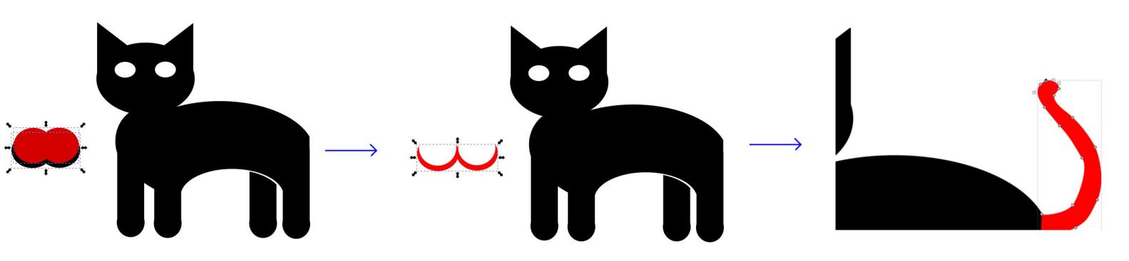
Figure N°3: Mouth and tail design
To create the food plate we will use a square to which we round the corners. With 2 symmetrically inclined rectangles we will do another Boolean subtraction. Finally we created food with ellipses and triangles to give it the shape of a fish, as well as some generic squares. (Figure No. 4)
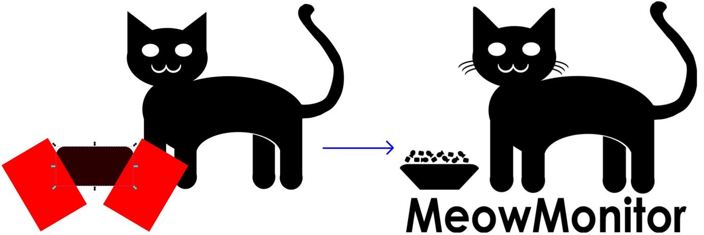
Figure N°4: Creation of the dish and food
The final file in .SVG format can be downloaded here.
For the second logo, we repeat the steps, we use a set of ellipses to form the cat's paw (Figure N°5)

Figure N°5: Footprints from ellipses
We make a mirror of the lower part looking for it to be symmetrical. Then using curves we create an outer environment and then do a Boolean subtraction of the footprints. (Figure No. 6)
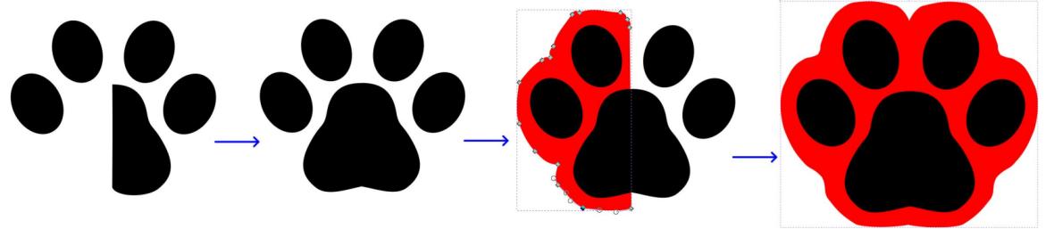
Figure N°6: Rounding the contour
We make use of straight lines to form a pulse signal to place inside the leg, finally we create the text but we curve it with the option "put in path" so that it follows the shape of a circle. (Figure No. 7)

Figure N°7: Text in the form of the path
The final file in .SVG format can be downloaded here.
In this section, we are going to use different software to create the same part and compare the results.
The first option is Fusion 360, in this software we are going to work with sketch in different planes, we start by selecting the ground plane and we create a 2 point rectangle establishing the dimensions of the edges. (Figure No. 8)

Figure N°8: Creation of the rectangle
Then we do an extrusion in the Z axis to turn the plane into a block. Additionally, we create a circle in one of the corners defining its radius and then delimiting the separation with the edges. (Figure No. 9)

Figure N°9: Placement of the circle
Later we extrude the created cylinder, then we use a linear pattern to repeat the figure 4 times horizontally and 2 times vertically. (Figure No. 10)

Figure N°10: Extrusion of the figure
With the figure created we use the "Shell" tool on the base and a hole is generated throughout the interior. Subsequently using the lower cylinders to use it as a reference for a new cylinder (Figure No. 11)
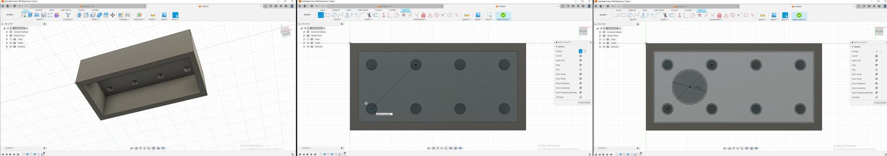
Figure N°11: Creation of the shell
Concentrically to the cylinder we create another but with a smaller radius, this section will then be extruded. Again we use linear pattern to have 3 times this section. (Figure No. 12)
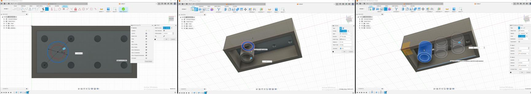
Figure N°12: Drawing of lower cylinders
When we already have all the sections designed, we only have to round the corners, for that we use the "Fillet" tool in all the parts that we want to round. (Figure No. 13)
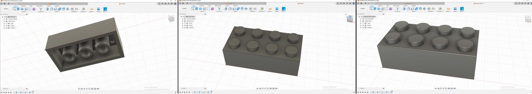
Figure N°13: Extrusion of cylinders
In the case of Fusion 360, it allows us to host our designs in the cloud and share them, you can access this file at the following. link.
The next software is Onshape, the workflow is very similar to the previous one since you also work with sketch within the views.
We locate ourselves in one of the axes and activate the sketch, draw a rectangle and establish the dimensions and then extrude the face. Then we create a circle and define the distances with the "Dimensions" tool. (Figure No. 14)

Figure N°14: Sketch of the rectangle
With the circumference created we use a linear pattern to have 8 of these circles to then extrude it. (Figure No. 15)
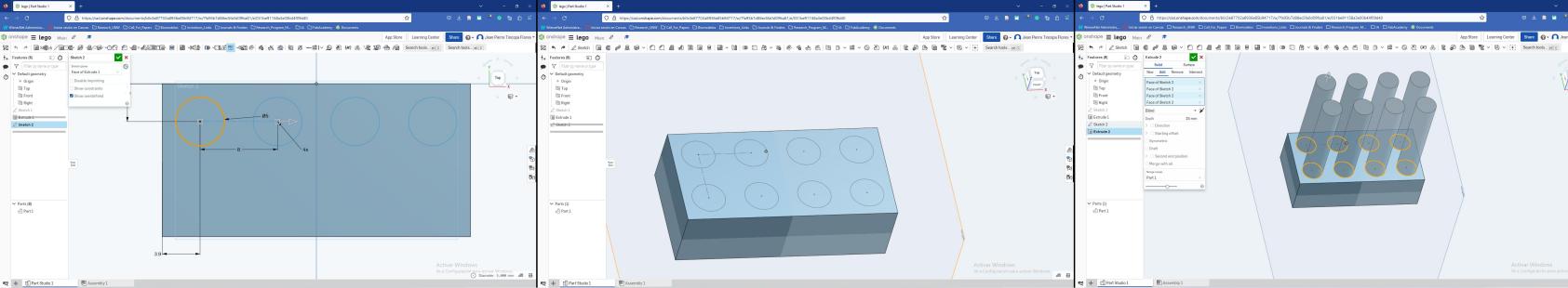
Figure N°15: Linear pattern of circles
Setting the proper extrusion size, we go to the bottom of the design and create a rectangle by setting the distance to the edges and then remove the rectangle with the "extrude" tool. (Figure No. 16)
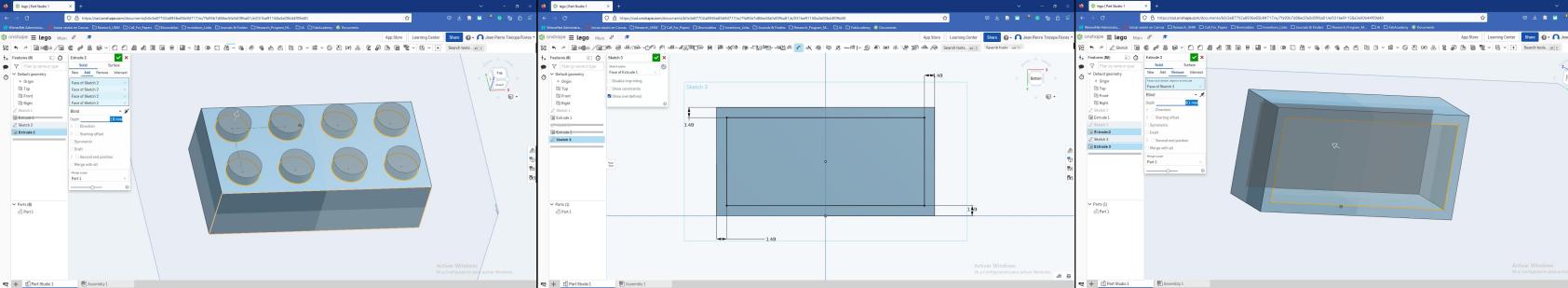
Figure N°16: Extrusion of circles
We repeat the steps in the lower part of the piece creating cylindrical sections to extrude them with the appropriate dimensions and the separation with the edges (Figure N°17)
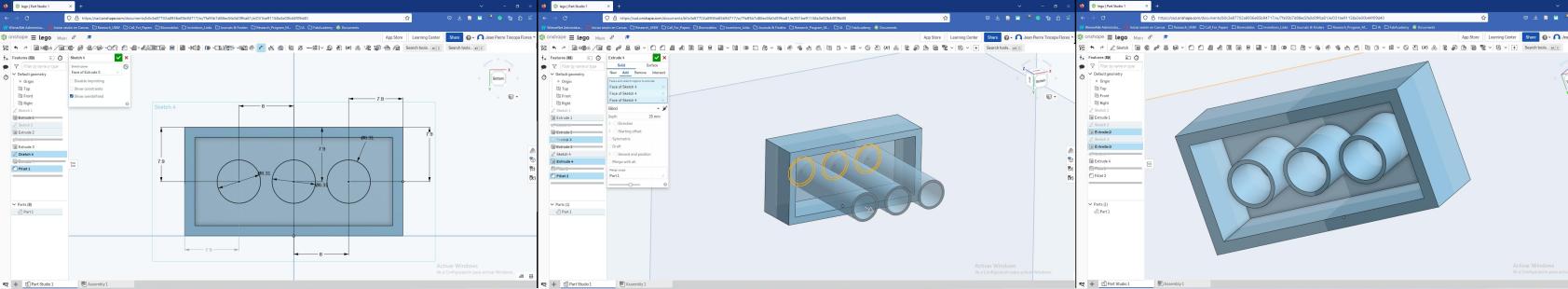
Figure N°17: Establishing dimensions
Finally we round the corners of several sections with the "Fillet" tool (Figure N°18)
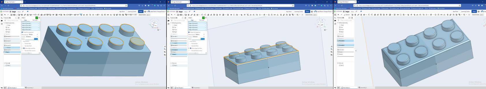
Figure N°18: Rounding of corners
Onshape also allows us to share the design in the cloud of our account, you can see the piece in the following link.
Finally, the last software that we are going to test is Blender, unlike the previous ones, it works by building meshes based on polygons.
To make the lego block we can use the cube that comes by default in the scene, modifying its dimensions. (Figure No. 19)
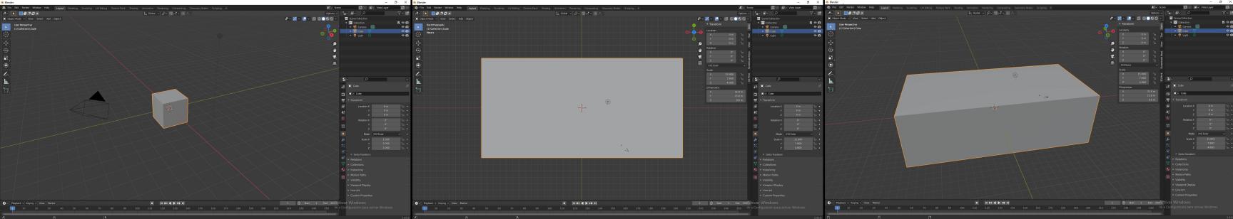
Figure N°19: Changing cube dimensions
Below this we create a duplicate that has smaller dimensions, with this we are going to use a modifier called Boolean that allows us to do operations between objects, in this case it is the difference mode. (Figure No. 20)

Figure N°20: Boolean operation in difference mode
Then we search among the basic figures and we will find the cylinder, when creating it with the appropriate dimensions we can use the "Array" modifier that allows us to make duplicates with a fixed separation between objects. Then we use these same pieces to make a boolean subtraction from the bottom. (Figure N°21)

Figure N°21: Creation of cylinders with Array
Having already completed the operation, we create a cylinder in the middle of the piece from below and then subtract it with another cylinder with a smaller radius. (Figure No. 22)

Figure N°22: Boolean difference from below
With this piece created, we duplicate it 2 times and then we move their locations symmetrically. (Figure N°23)
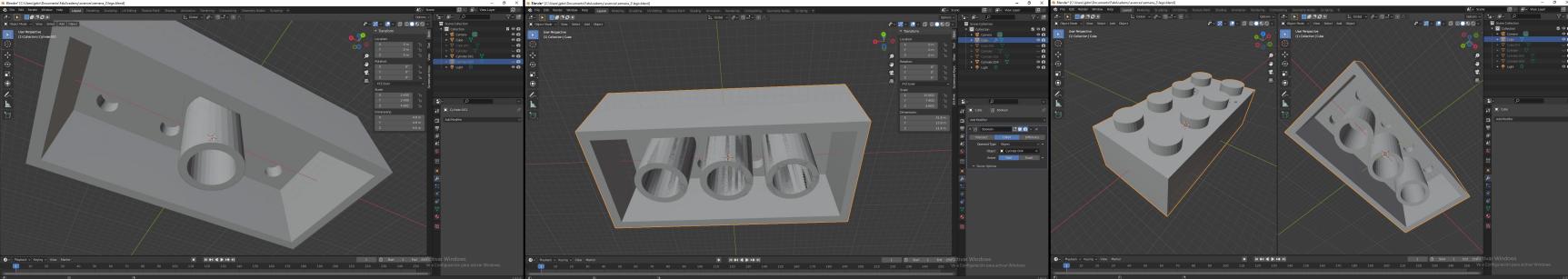
Figure N°23: Modeling lower cylinders
To soften the corners we use the "Bevel" tool in the corners. Already having the piece we can give color to each object in the scene including the floor. (Figure No. 24)

Figure N°24: Beveled corners and texturing
For the floor we use a texture from an image (Figure N°25)
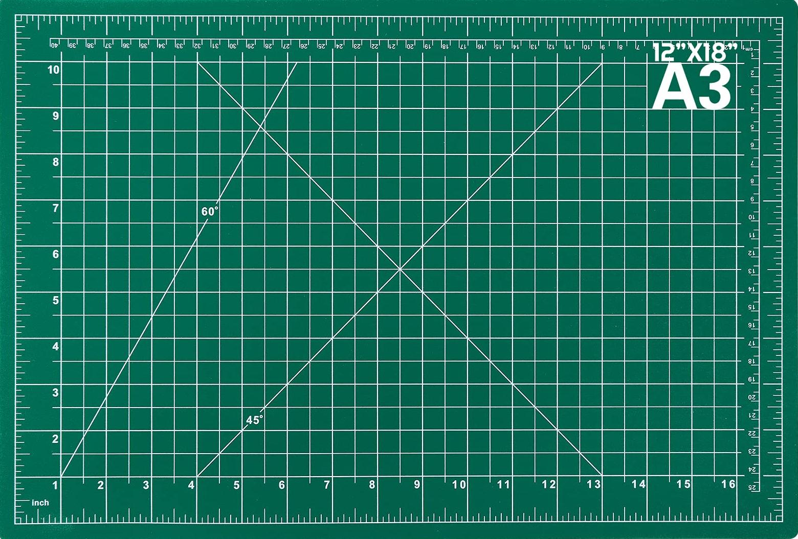
Figure N°25: Cutting mat texture
The final result can be seen in figure N° 26.
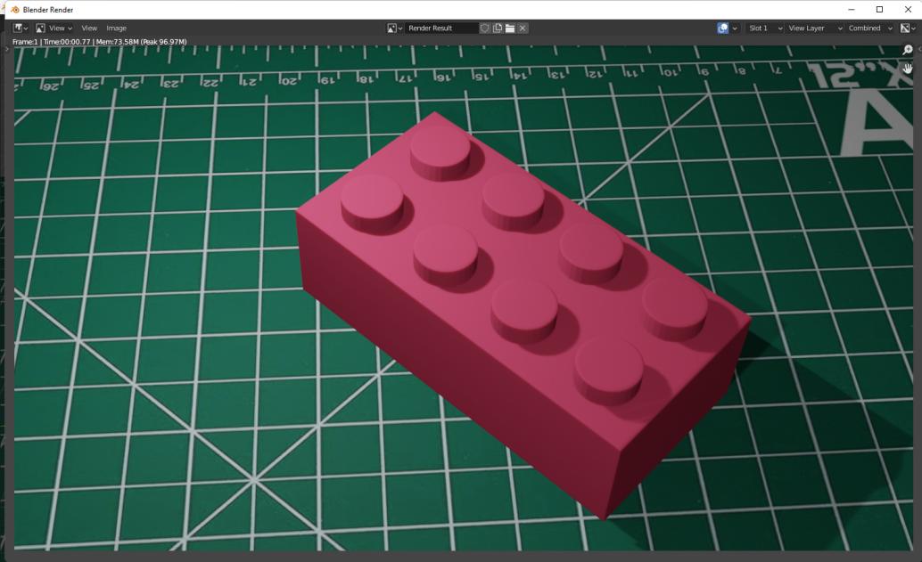
Figure N°26: Rendering with textures
The final file in .blend format can be downloaded here and the lego block in .STL can be downloaded here.
In order to transform an image from 2D to 3D we will use the Blender software, here we can import a file in .SVG format. When it is already inside the scene we can see that it behaves like beizer curves, in order to convert it to a set of polygons we look for the "Convert mesh" option. (Figure No. 27)
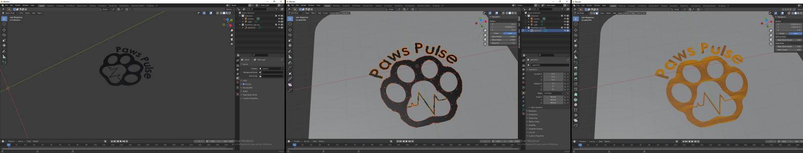
Figure N°27: Importing the vector
As it is a set of points, it is necessary to clean duplicate meshes, for them we use the "Clean-Up --> Merge by distance" option to eliminate unnecessary points. Later we can extrude this logo and then use a boolean difference on a surface. (Figure No. 28)
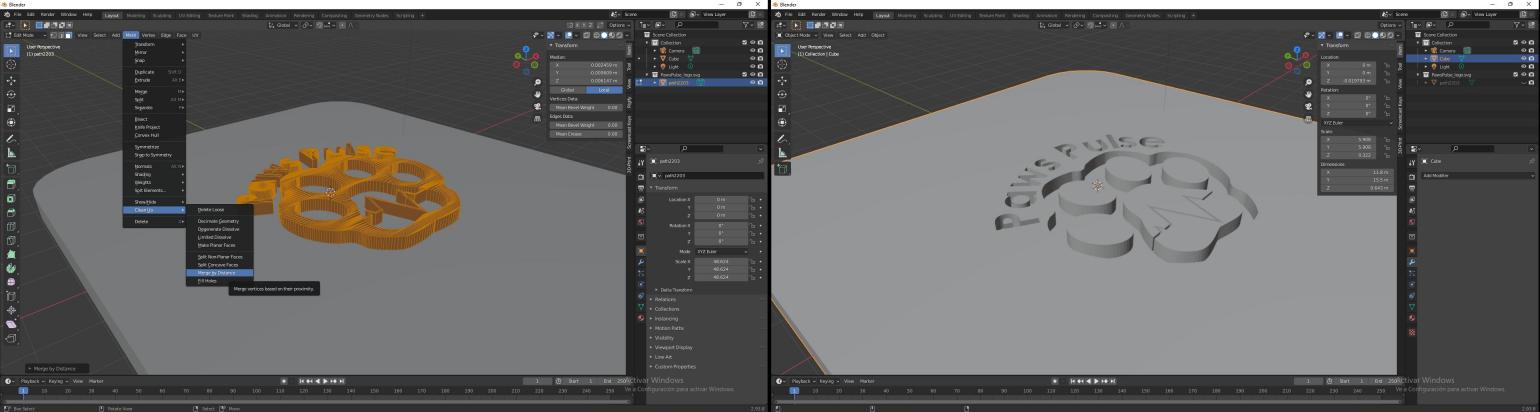
Figure N°28: From curve to mesh
We can render the resulting object, in this case a surface texture called "Subsurface scattering" was chosen. (Figure No. 29)
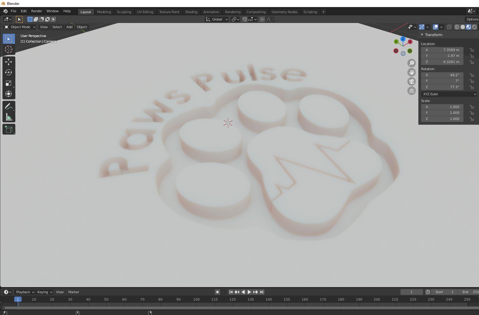
Figure N°29: Render as plastic surface
The final file in .blend format can be downloaded here.
We try the same for the other logo in .SVG format, when it is imported and cleaned we can do a boolean subtraction with respect to another object. (Figure No. 30)

Figure N°30: Boolean operation with the mesh
In this case we will use a cardboard texture to resemble a laser cut in MDF. (Figure No. 31)
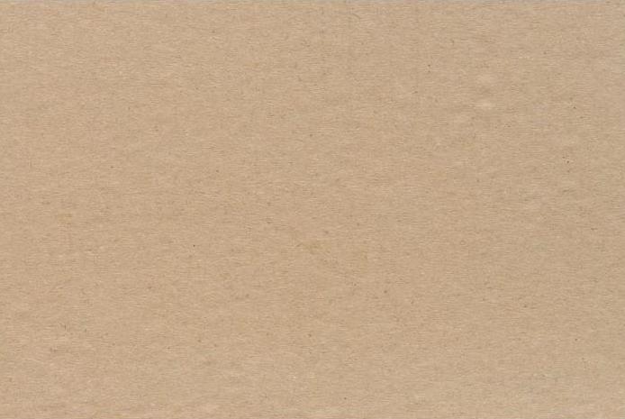
Figure N°31: Cardboard texture
The result of this can be seen in figure No. 32.
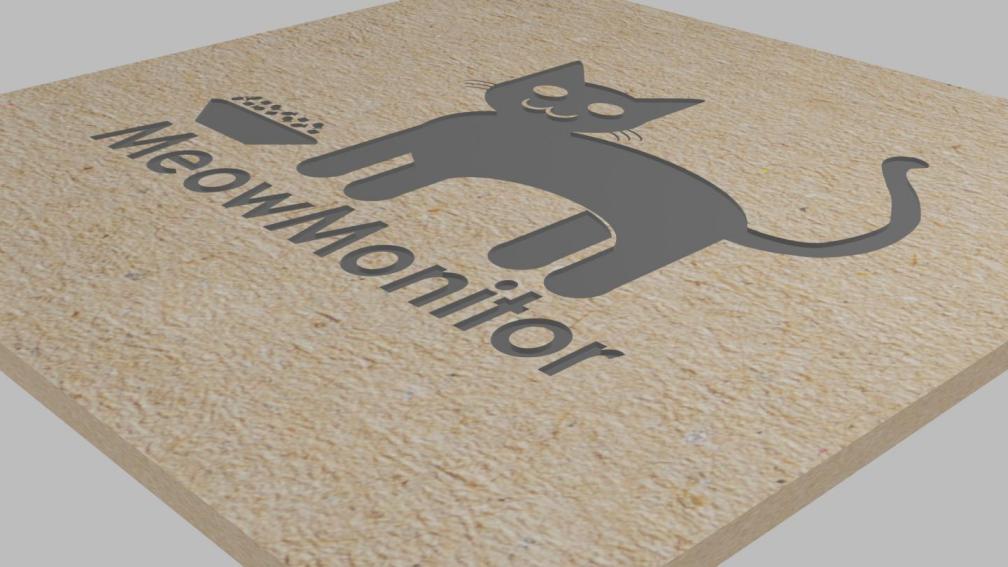
Figure N°32: Render with MDF texture in laser cut
The final file in .blend format can be downloaded here.
As part of the final project, a hinge has been designed in 3D, this will help us to have compartments inside the cat feeder. This design is unique in the Individual Assignment section of week 5, you can go directly to this link.
Artificial intelligence is booming these days as many image generators have emerged with this technology, which are created from prompts.
For this experiment, Midjourney was used from the Discord platform. It uses the command "/imagine" followed by the statement that works as a prompt.
In the first attempt I tried to generate a 3D design of a helmet in the shape of a cat. The idea was to generate a blueprint that later allows you to design from it in one of the 3D modeling software.
The first prompt used is the following:
blueprint of a cat-shaped robotic helmet
The result of this can be seen in Figure No. 33.
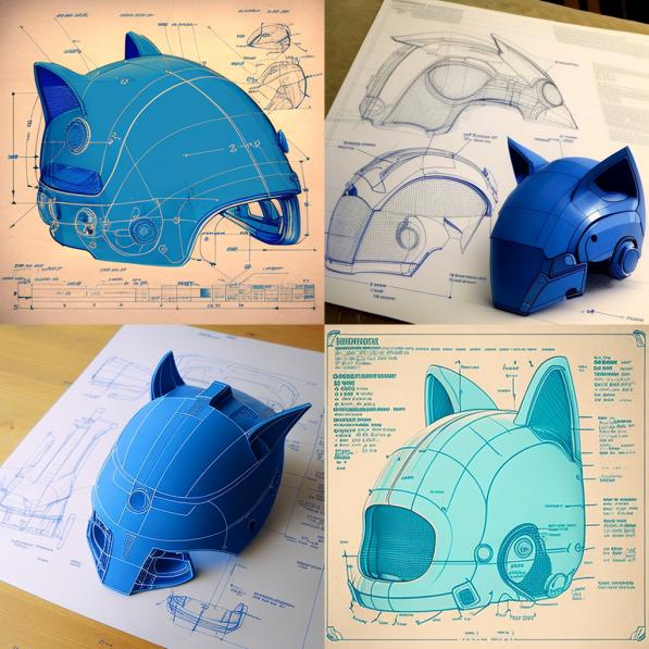
Figure N°33: First helmet attempt
For the following attempt, I tried to be more specific, the prompt used is the following:
blueprint of a cat-shaped robotic helmet for technical drawing and that includes exact dimensions in millimeters with 4 views: elevation, profile, plan and isometric
The result of this can be seen in Figure No. 34.
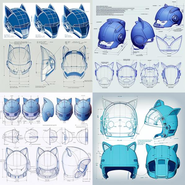
Figure N°34: Second attempt at a detailed hull
This platform allows us to improve the resolution of one of the 4 options that it generates automatically. When enlarging one of the images obtained, we see that it fails to create 3 views of the same design. (Figure No. 35)
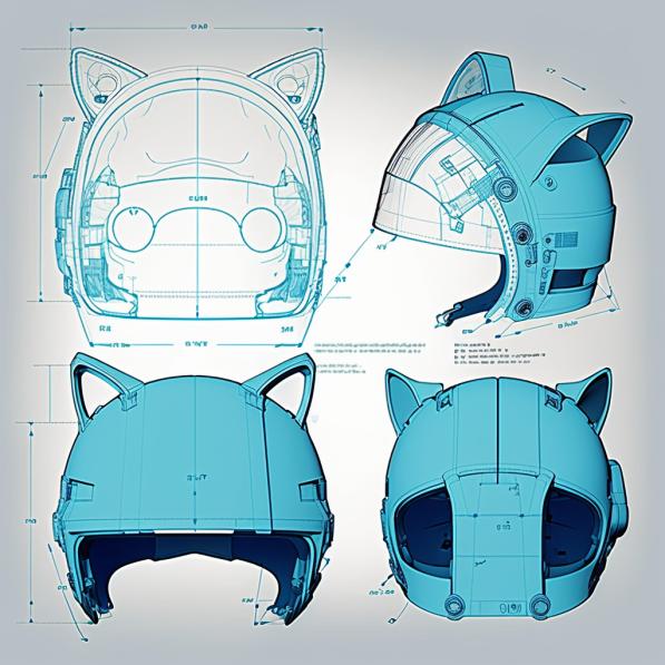
Figure N°35: Previous result with higher resolution
Redirecting the experiment to the proposed final project of an automatic cat feeder, we will seek to generate a blueprint with 3 points of view of the same object.
The prompt used is the following:
Blueprint of an automatic cat feeder with its plate, autocad style, including exact dimensions in millimeters, with 4 views: top, front, side and isometric of the same design
The result of this can be seen in Figure No. 36.

Figure N°36: First attempt at Autocad-style automatic feeder
Retried adding the term "very detail" with style "Fusion 360"
The prompt used is the following:
Blueprint of an automatic cat feeder with its plate, "fusion 360" style, with 4 views: top, front, side and isometric of the same design, very detail
The result of this can be seen in Figure No. 37.
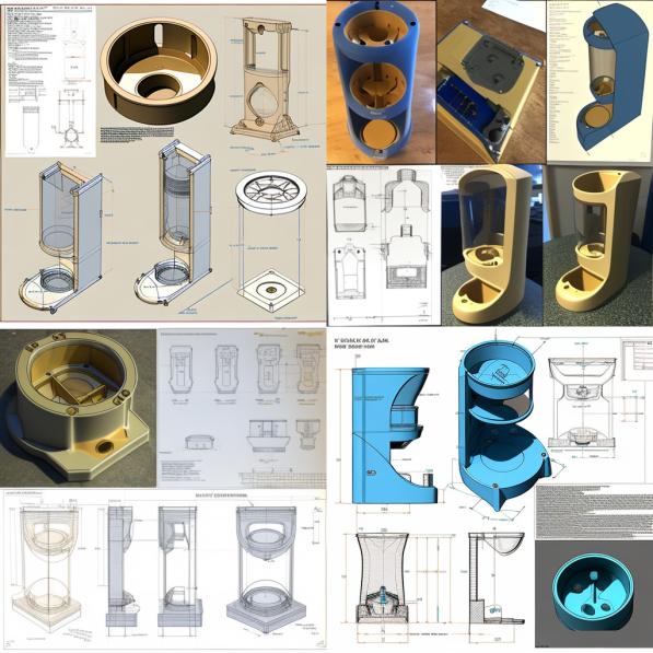
Figure N°37: Second attempt at Fusion 360 style automatic feeder
One last attempt was made now only looking for 2 points of view.
The prompt used is the following:
Blueprint of an automatic cat feeder with its plate, "fusion 360" style, with 2 views: front and side of the same design, very detail
The result of this can be seen in Figure No. 38.

Figure N°38: Third attempt at Fusion 360 style auto feeder with 2 views
The expected exact result was not obtained, since the dimensions of the blueprints are not well appreciated and in all cases at least one of the 3 views does not correspond to the same design.
In conclusion, these images obtained cannot be used directly to be used in computer-aided design, but they can serve as inspiration for the design of the final project.