
This week's assignment was to explore the additive technology mainly focused on 3D printing, also analyzing its limits. Additionally, different scanning software has been tested to obtain acceptable results.
For this section we are going to test the design rules of our 3D printers
We begin by defining the machines with which we are going to work, the first is a Creator Pro model from Flashforge brand (Figure N°1). We can see its technical specifications in Figure No.2
The manufacturer's link is this.
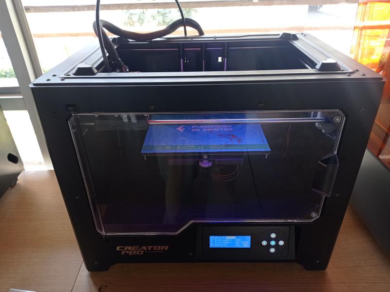
Figure N°1

Figure N°2
Video N°1
To know the capacities and limits of the machine, several tests of the design rules were printed. The first was the one that evaluates at what angle of inclination a deformation begins to be seen in the model. (Figure No.3)
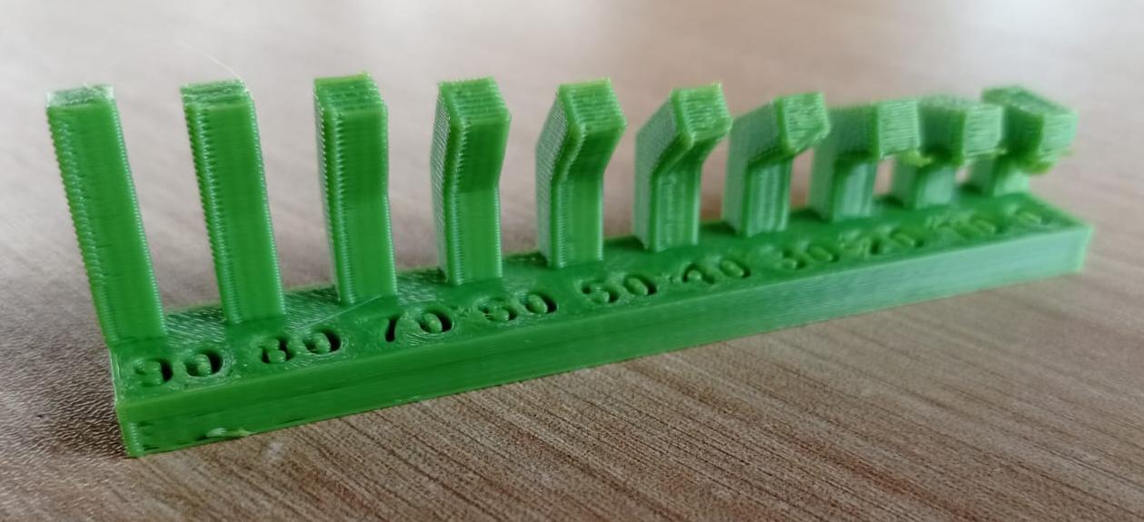
Figure N°3
We see the result in Table No.1 where it can be seen that from 40° it is necessary to use supports.
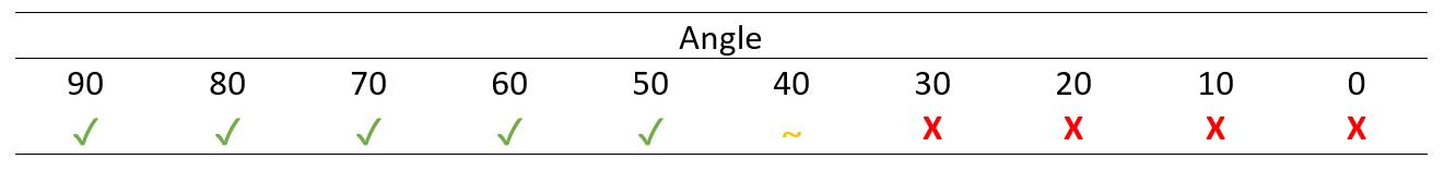
Table N°1
The next parameter is the overhang, where we see from what straight distance the model deforms.
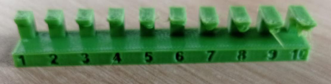
Figure N°4
We see in Table No.2 that from the shortest distance it is necessary to place supports.

Table N°2
Continuing we are going to see bridging, that is, having two posts from what distance the piece is deformed.
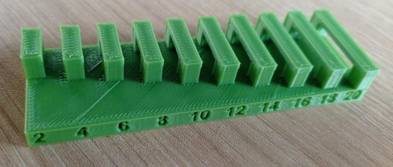
Figure N°5
We see in Table No.3 that from 16mm it is only necessary to place supports on the piece.
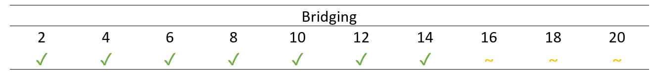
Table N°3
The next parameter is the clearance, in which we observe how much clearance or separation distance is necessary in an impression so that it can move without problems.
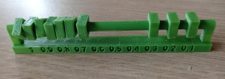
Figure N°6
In the results of Table No.4 we observe that we must have a separation of 0.4mm or greater so that the printed pieces can be separated.

Table N°4
Finally, the last parameter is the thickness of both the walls and the holes, these were compared between the theoretical dimensions and the real ones measured by a digital vernier.
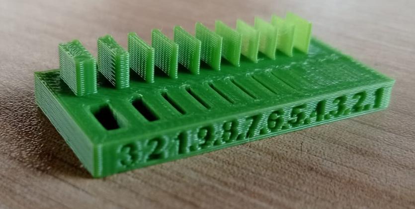
Figure N°7
We can observe in Table No.5 the differences in the dimensions, being that there is a greater error in the walls than in the holes.
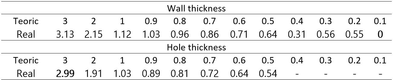
Table N°5
The second machine that we are going to use is a Guider II model, also from the Flashforge brand (Figure N°8). We can see its technical specifications in Figure No.9
The manufacturer's link is this.
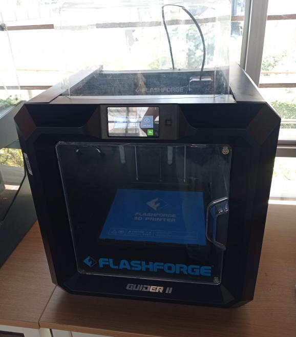
Figure N°8

Figure N°9
Video N°2
We first evaluate the angle of inclination. (Figure No.10)

Figure N°10
We see the result in Table No.6 where it can be seen that after 30° the use of supports becomes necessary.

Table N°6
The next parameter is the overhang, where we see from what straight distance the model deforms.

Figure N°11
We see in Table No.7 that, as in the other machine, it is necessary to place supports from the shortest distance.
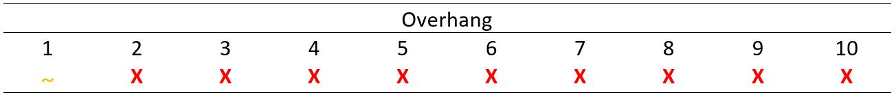
Table N°7
Now in the case of bridging, to see how far the part is deformed.
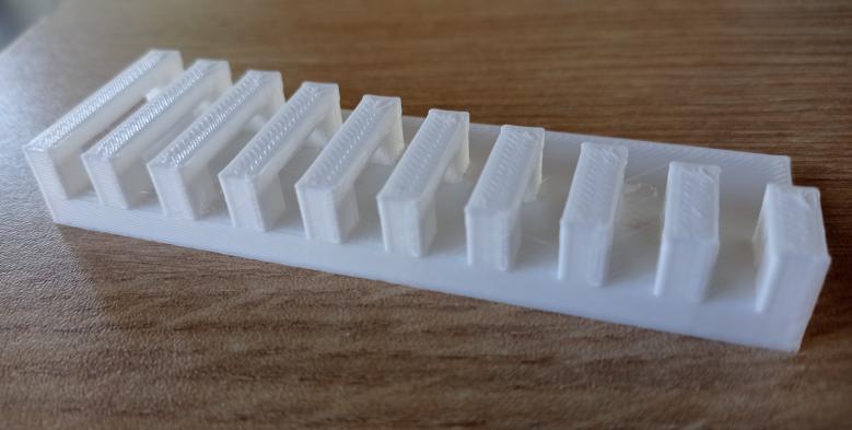
Figure N°12
We see in Table No.8 that from 18mm it is only necessary to place supports on the piece.
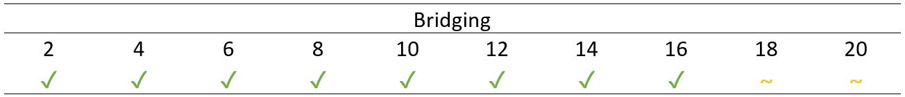
Table N°8
For the clearance where we observe how much clearance or separation distance is necessary in an impression so that it can move without problems.

Figure N°13
In the results of Table No.9 we see that we must have a separation of 0.4mm or greater so that the printed parts can be separated.

Table N°9
Finally, the last parameter is the thickness of both the walls and the holes, these were compared between the theoretical dimensions and the real ones measured by a digital vernier.

Figure N°14
We can observe in the table No.10 the differences in the dimensions, being that there is a greater error in the walls than in the holes, the same as in the other machine.
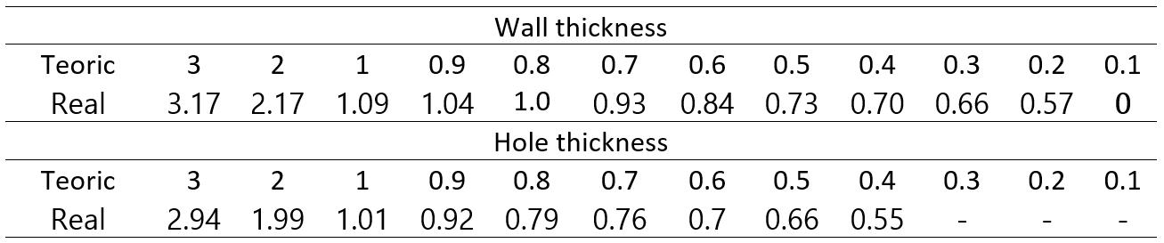
Table N°10
Moving on to another manufacturing technology, tests were made on a Form 3 of the Formlabs brand, this printer is an LF SLA, which would be a successor to SLA; in this case, he uses a flexible tank and linear lighting to transform the liquid resin into pieces. The more flexible the tank, the lower the force. (Figure N°23)
The manufacturer's link is this.
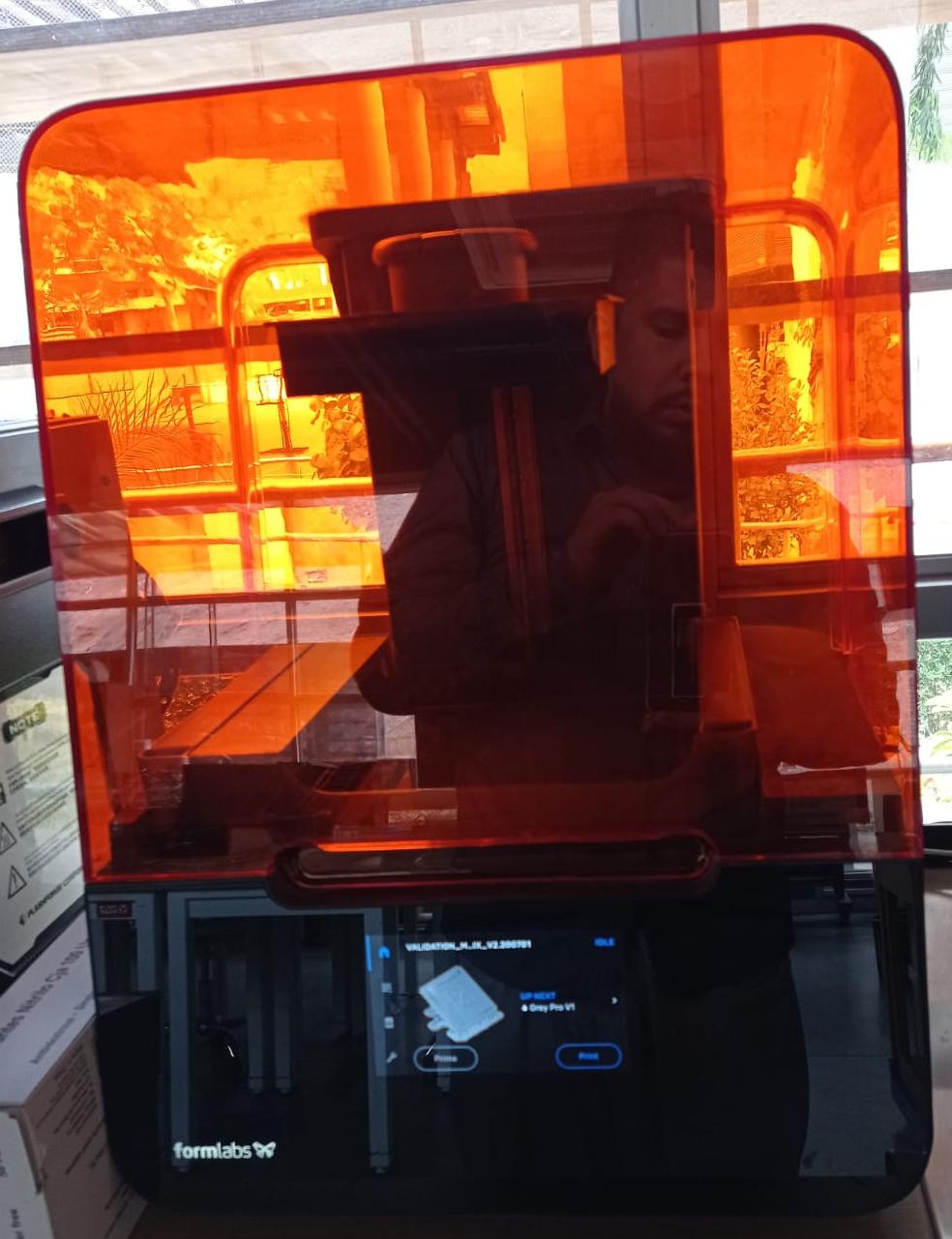
Figure N°15
We can see its technical specifications in Figure No.16
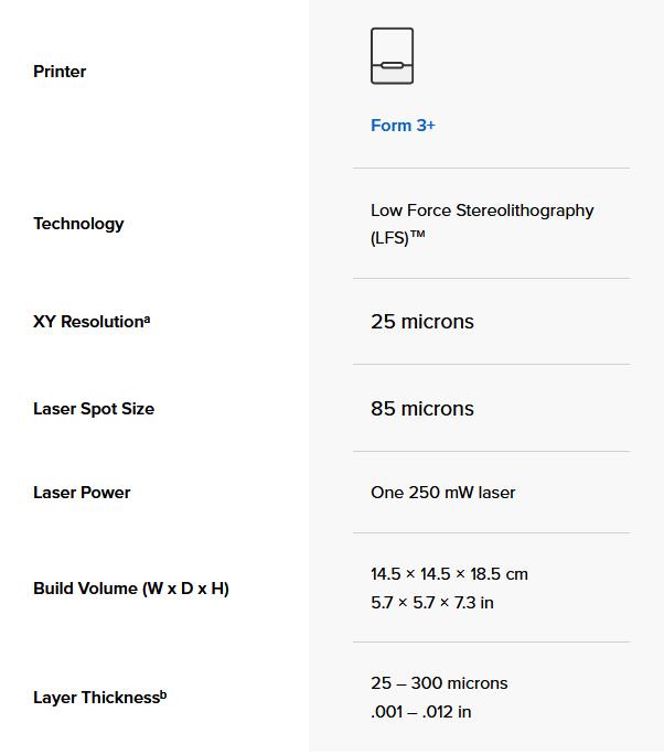
Figure N°16
The design that was used for this test is a validation matrix that contains many forms of different measurements that will allow us to appreciate the precision of the machine.
The first step is to upload this file to the software called PreForm which has many tools that will help us optimize printing.
The first is the optimal tilt, since it is recommended in this technology not to print something completely tilted. Likewise, when the figure is well oriented, we proceed to place the supports. (Figure No.25)
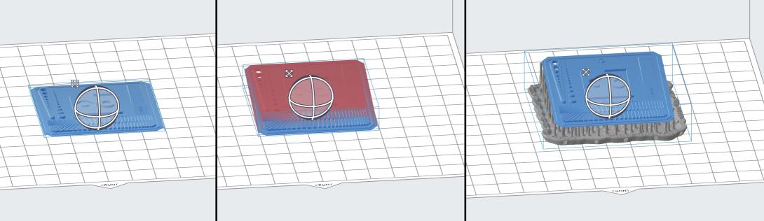
Figure N°17
Another important parameter is the location, in the same way the software automatically chooses the most optimal place inside the heated bed to print. (Figure No.18)
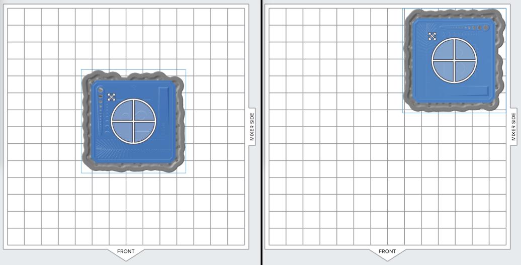
Figure N°18
In figure No.19 we can see the printing details such as delay time and the volume of resin to use.

Figure N°19
When we have already loaded this file to the machine we can use its touch screen to start the work. (Figure No.20)
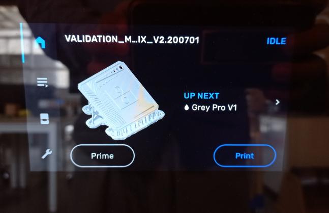
Figure N°20
It is important to note that in order for the content of the resin bottle to be pulled into the work space, its lid must be open. (Figure No.21)
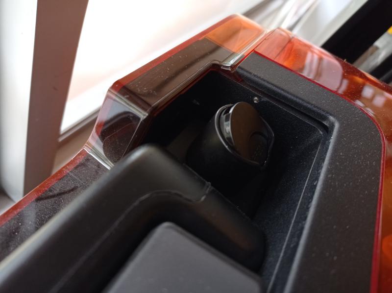
Figure N°21
In figure No.22 we can see the result of printing the validation matrix.
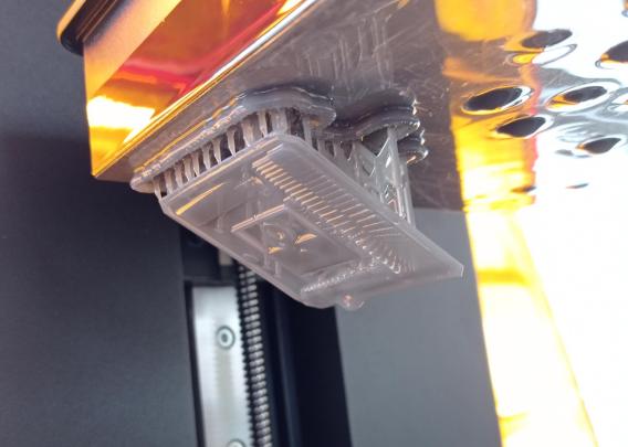
Figure N°22
The next step after printing is to pass it to the washing machine. In this we can determine how long the piece will have to be washed in isopropyl alcohol. (Figure No.23)

Figure N°23
Finally, the final step to finish the piece is to use the curing machine which uses high temperatures and UV light to give the final finish.

Figure N°24
We can see in figure N°25 that the test was successful in all the ways established by the validation matrix.

Figure N°25
For this section we are going to design in 3D a small object that could not be easily made subtractively.
Having clear the limits of 3D printing, the task is to print a part that cannot be done through subtractive manufacturing, for this reason it was chosen to design a hinge that does not need supports and is capable of moving as soon as its manufacturing is finished.
This design was made in Blender, we start the design from a cylinder where we move its vertices in 2 axes.
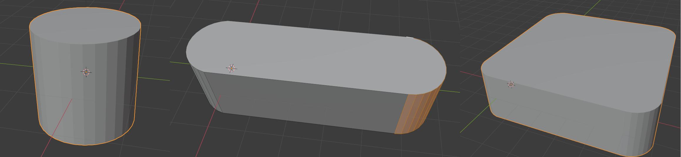
Figure N°26
We select all the vertices of one of the sides and shrink them so that they form a wall. We added another cylinder and changed its orientation, created several subdivisions, and removed the walls to separate it into several cylinders.

Figure N°27
Based on the same axis we create an inner cylinder, now that we know the value of clearance we are going to use the boolean tool in difference mode to create a difference between the radius of the cylinders of 0.4mm as we got in the clearance tests.
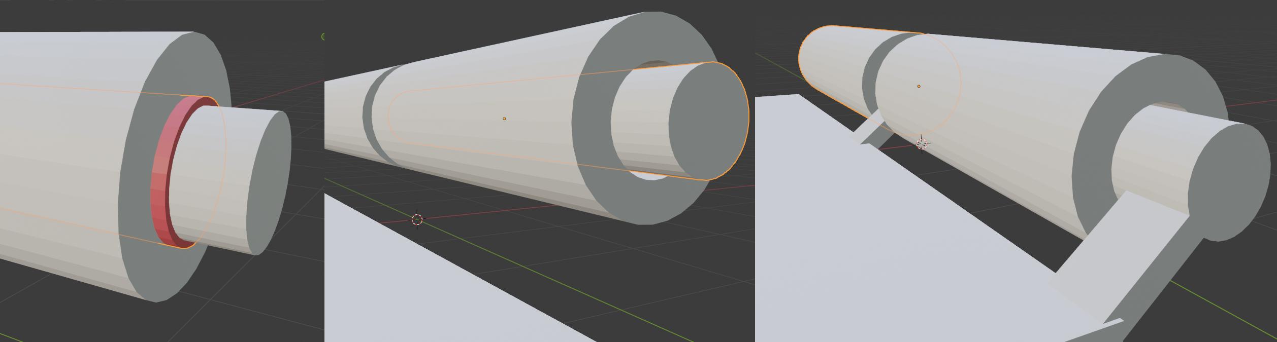
Figure N°28
We extruded several faces to join both pieces.

Figure N°29
2 designs were made, one with 2 sections and 3 sections (Figure No.27)
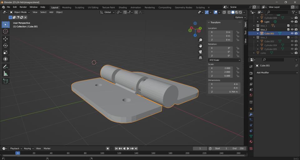
Figure N°30
In order to laminate this piece on both machines, the Flashprint software was used in its version 4.6.0. (Figure No.28)

Figure N°31
Hinge printing was successful on both 2 and 3 section machines. (Figures No.29,30,31,32 and 33)
We also see in videos No.3,4,5 and 6 how they were completely mobile.

Figure N°32

Figure N°33
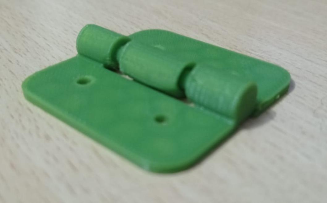
Figure N°34
Video N°3
Video N°4

Figure N°35

Figure N°36
Video N°5
Video N°6
Finally, to finish the assignment for the week we have 3D scanning, there are many apps or programs that allow you to perform this task using photogrammetry. That is, they create the 3D model from a set of photos.
For this test, the object to be scanned will be a Grogu doll (Baby Yoda), in the scene a cutting mat was placed at the base to serve as a reference in the photos and there was only one illumination just above the object to the shadows are not altered. (Figure No.34)
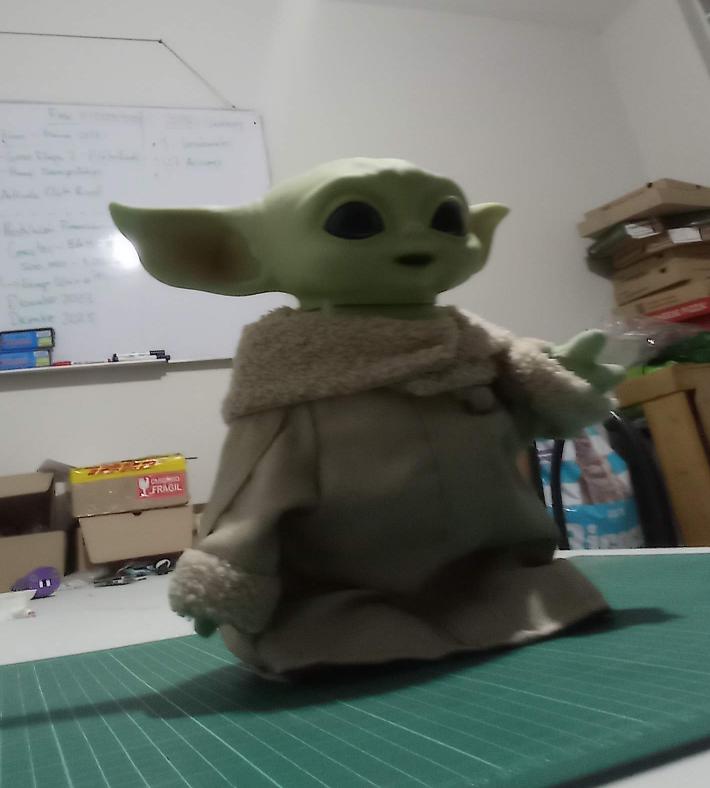
Figure N°37
The first test was carried out using Polycam (Figure N°35) this is an app that processes images in the cloud, it is paid but it allows you to do 7 free scans.
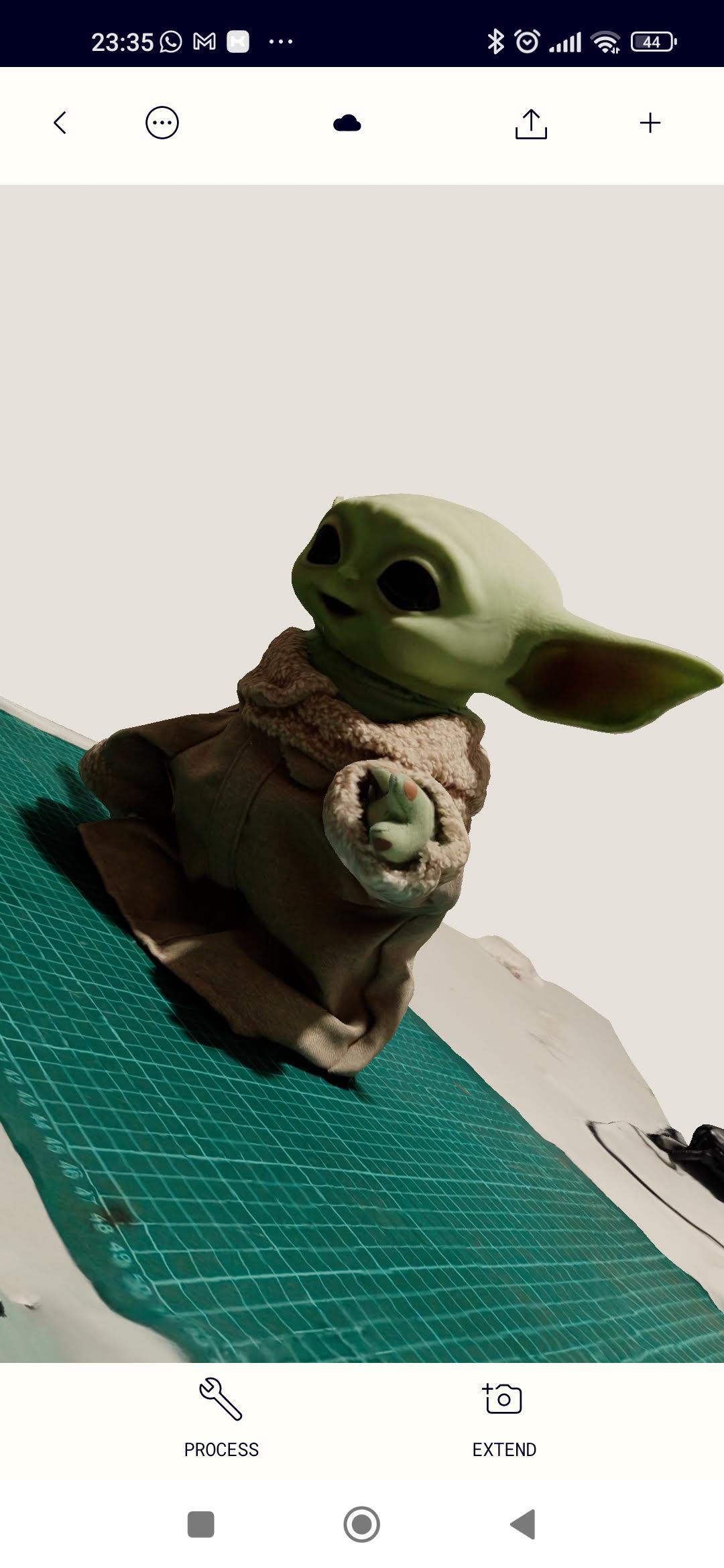
Figure N°38
The next app is Kiri Engine, in the same way it also uploads the photos to the cloud and processes them (Figure No.36)
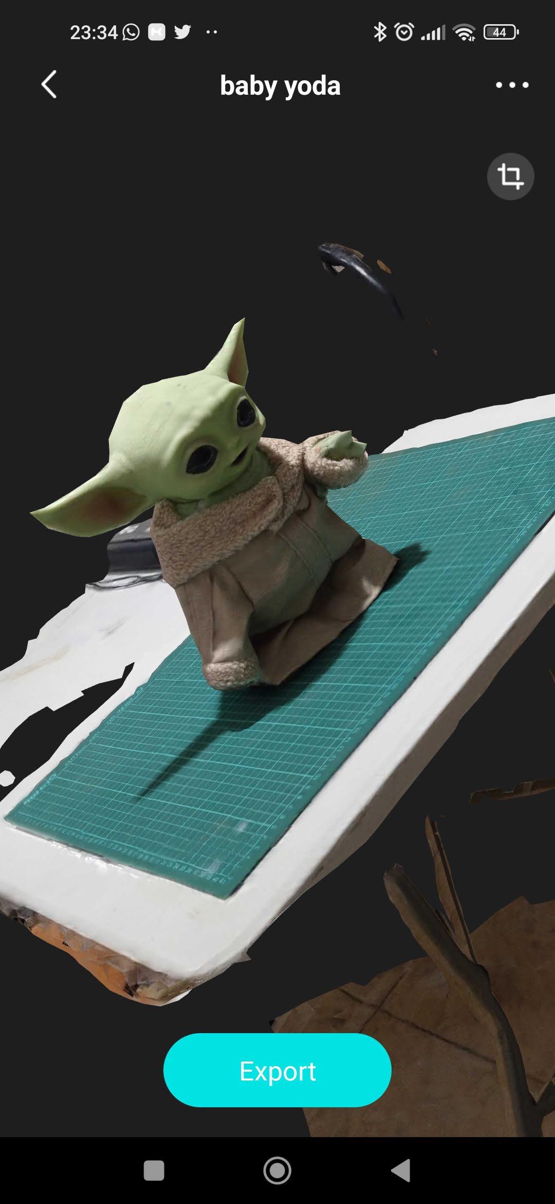
Figure N°39
The third and last option is Scann3D which works in a similar way to the other mentioned options. (Figure No.37)
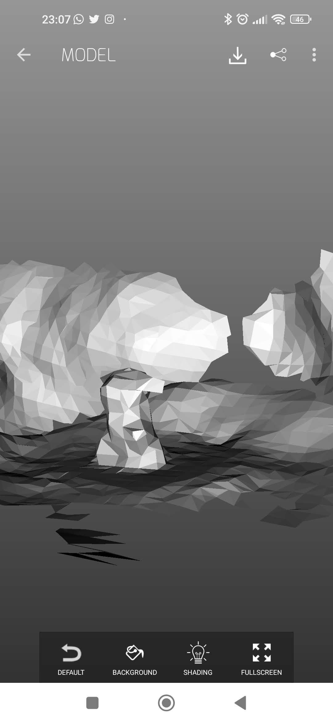
Figure N°40
Some of these software require a subscription or payment to be able to export the model in .STL format. Being that most export in .GLTF format which is a format that includes textures.
Analyzing the results of the scanning process we see that in the case of Scann3D it had a rather deplorable result since the number of polygons in the scene was very low. It was followed by the Kiri Engine which, although it has a better resolution, the polygons were still few and on round surfaces it makes them look square.
For all this Polycam was the one who had the best performance by having a fairly good number of polygons and having a correct placement of textures.
This model was imported into Blender. (Figure No.38)
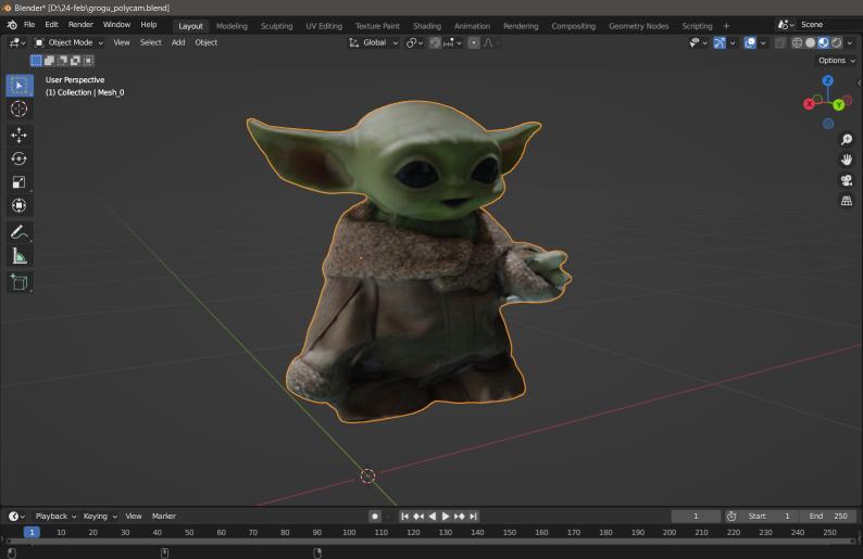
Figure N°41
We can see the number of triangles in the model in Figure No.39
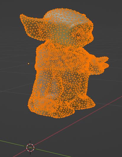
Figure N°42
In order for this model to be printable, everything that does not belong to the model of the doll had to be subtracted and additionally closing the mesh so that it is interpreted as a solid in the laminating software. (Figure No.40)
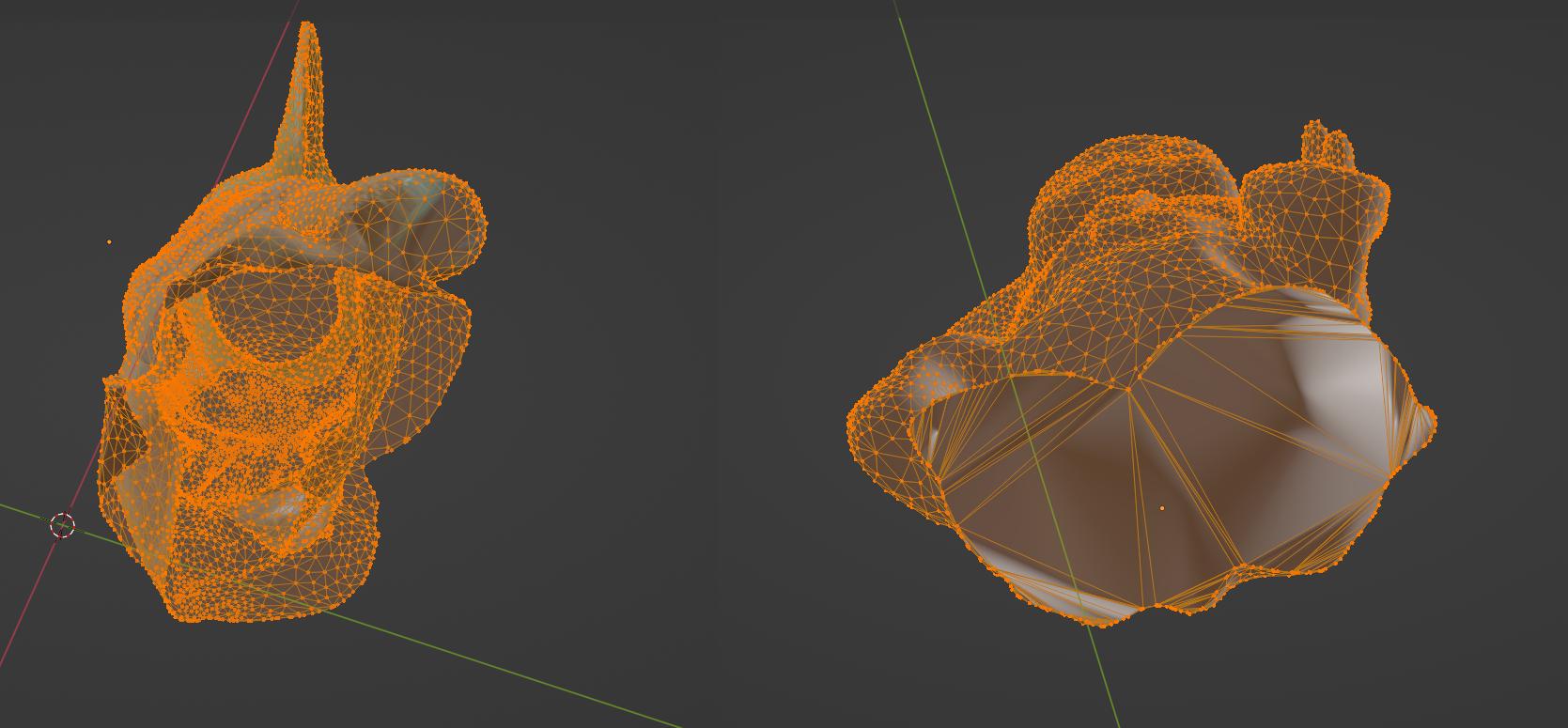
Figure N°43
The final file was printed on Guider 2, this print lasted a total of 12 hours. (Figure No.41)
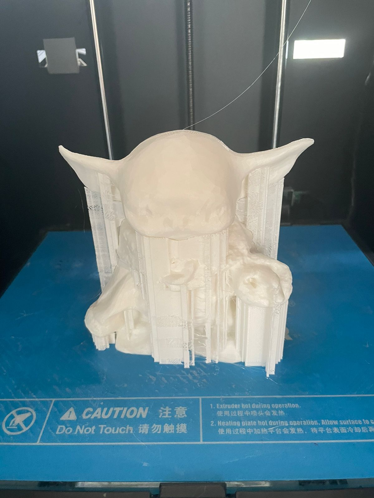
Figure N°44
We will be able to appreciate the final result after removing the supports in Figure N°.42
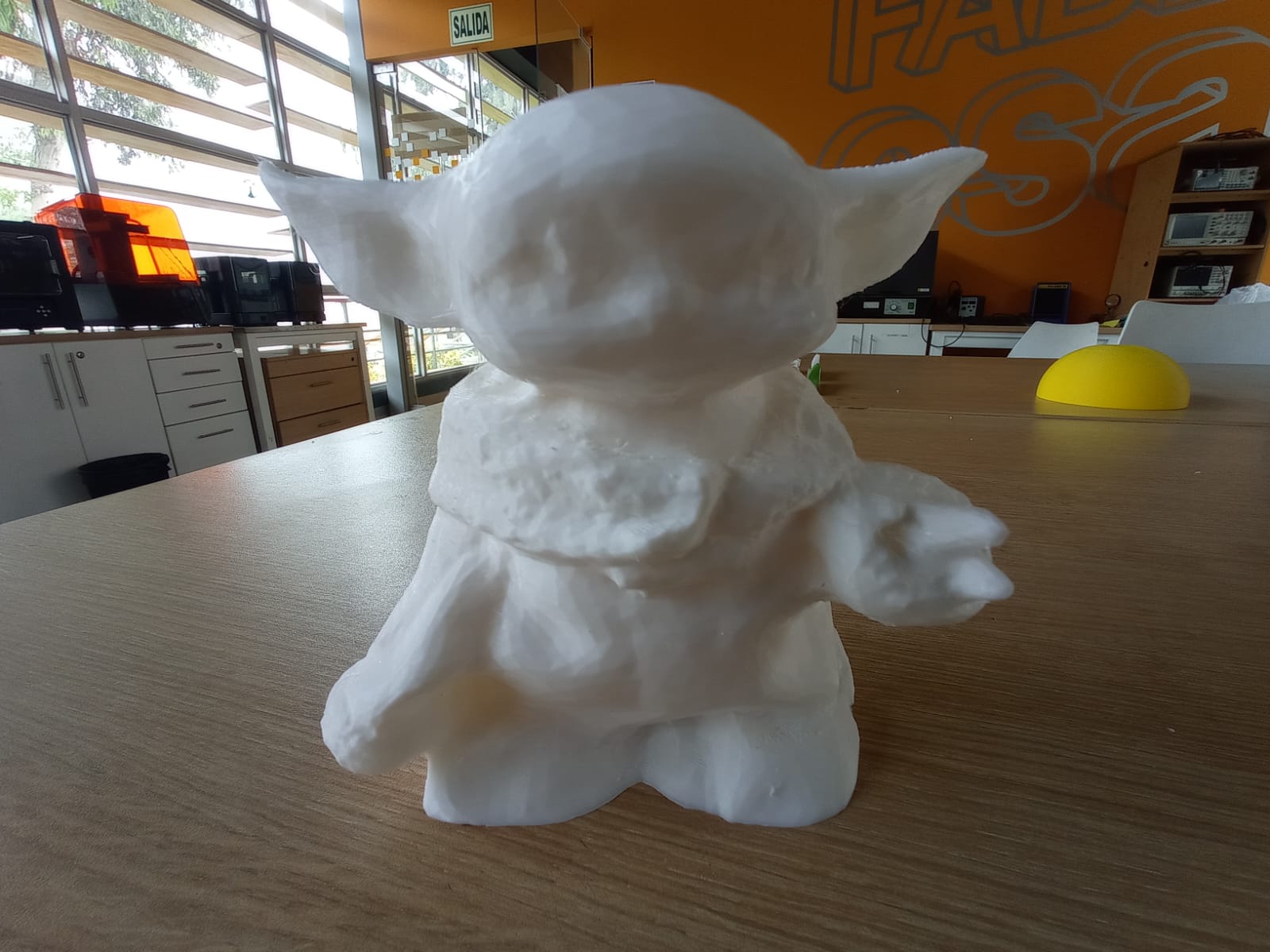
Figure N°45
The files created or used this week can be downloaded here:
| Design rules - clearance | Link |
| Design rules - angle | Link |
| Design rules - overhang | Link |
| Design rules - bridging | Link |
| Two-part hinge | Link |
| Three-part hinge | Link |
| Grogu scan | Link |
| Resin test | Link |