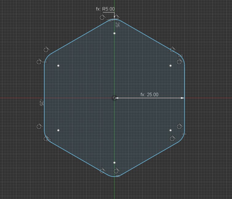
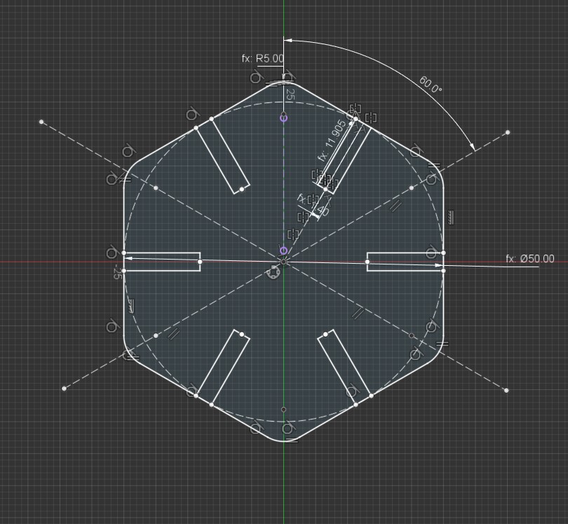
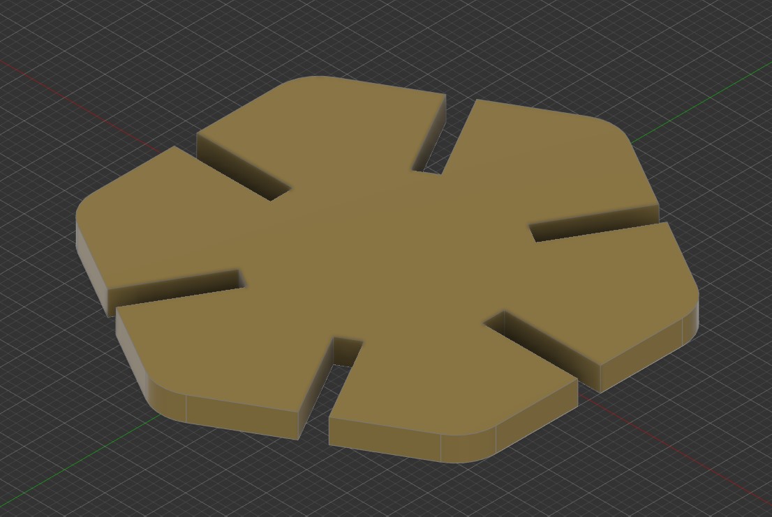
In my lab we have different machines:
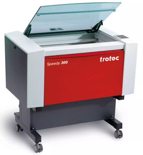
Working area : 726 mm x 432 mm
Working hight : 200 mm
Max working speed : 3.55 m/s
Power : 60 W
This Machine is design for proffesional.
We can use different plate to support our material. We have also the possibility to have a rotary attachement to use the machine with cylindrical object like glass or thermos.
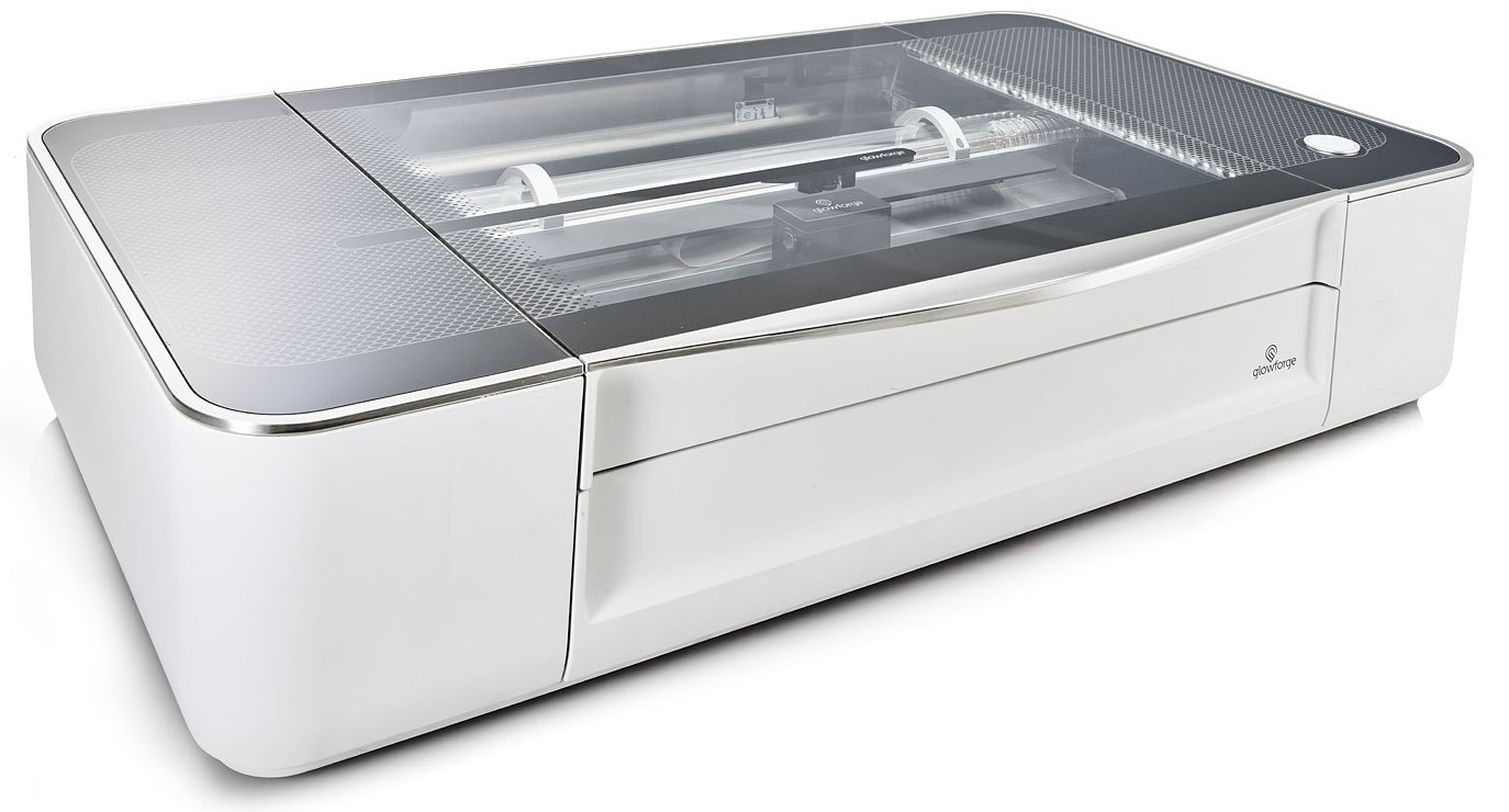
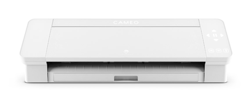
Working area : 495 mm x 279 mm
Working hight : 50 mm
Power : 45 W
This machine is design for maker or semi-proffesional persone.
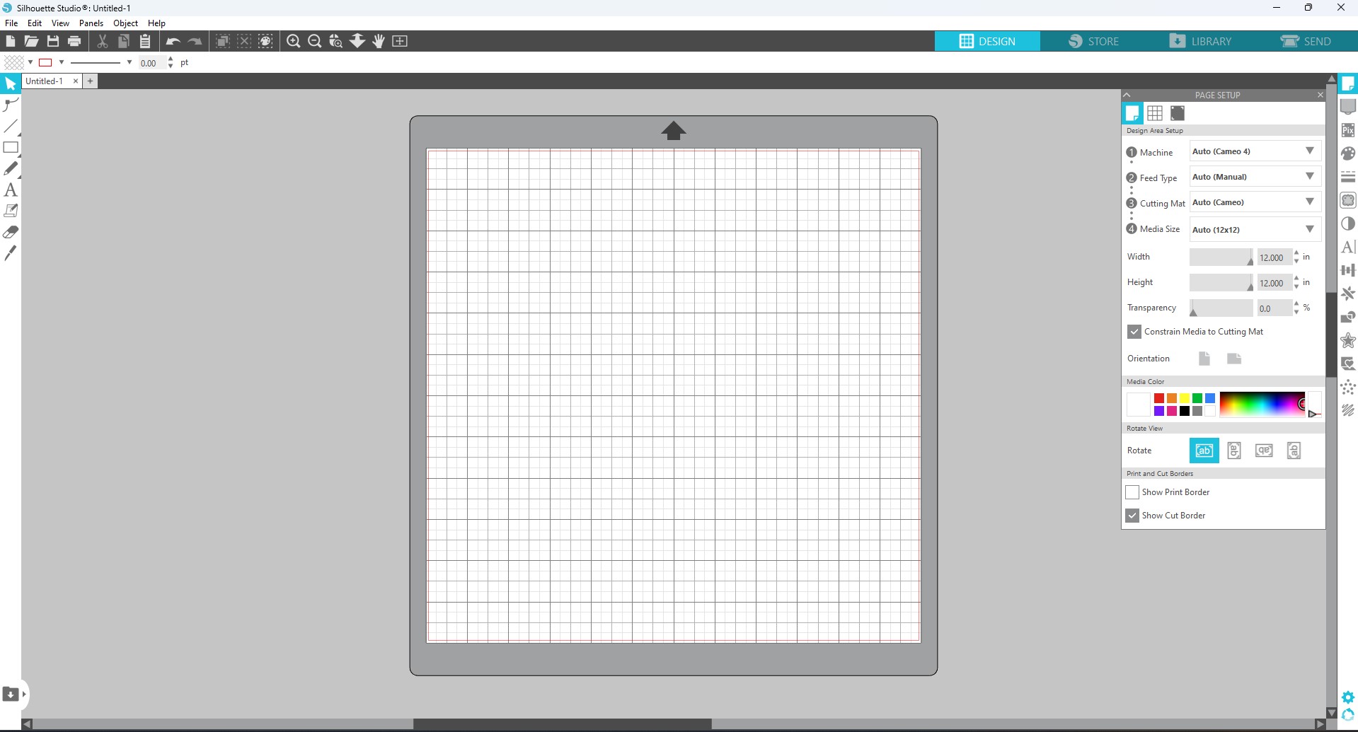
you can control it directly, you need to use a software online with pay feature.
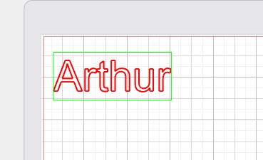
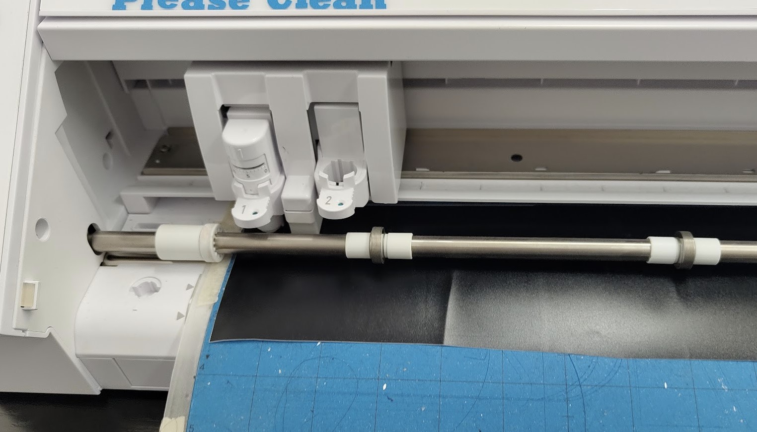
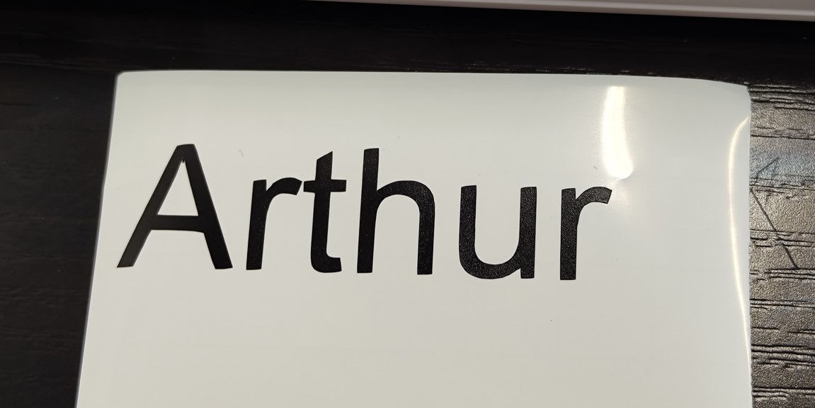
when we finish the design and send it to the machine, we press the only button to lunch the cut.
Laser cutting is a technology that uses a laser to vaporize materials, resulting in a cut edge. While typically used for industrial manufacturing applications, it is now used by schools, small businesses, architecture, and hobbyists. Laser cutting works by directing the output of a high-power laser most commonly through optics. The laser optics and CNC (computer numerical control) is used to direct the laser beam to the material. A commercial laser for cutting materials uses a motion control system to follow a CNC or G-code of the pattern to be cut onto the material. The focused laser beam is directed at the material, which then either melts, burns, vaporizes away, or is blown away by a jet of gas, leaving an edge with a high-quality surface finish
source: Wikipedia
For the rest of this assignement we decide to use the Trotec cause is easier to customise the setting compare to the Glowforge
Differents setting can be modify to have a perfect cut.
The focus:
Is the capacity to have the laser in a single point, this way all the power converge and can cut or engrave what we want. its like in photography, if you want to take a picture of somthing, the focus help to have a good picture, if it too close or too far is blurry. this is why we exprimate the focus whit a distance.
In my case is fix, the machine is not capable to change the focus point, Trotec provide us a reference gauge to set the focus of the machine whit tis procedure.
The speed and the power are linked. If you but a small power but move very slowly you can have the same result that full power but really fast.
So those two setting will be set a the same type with some test cut.
I find this test cut, is an SVG file we can edit and use to cut with the Laser cutter.
We change change the text on it with the Speed and the Power for the engraving and the cut action.
The result is a piece we can look and see what is good or not and change the setting in concequence.
To test i use plywood cause is somthing we have a lot at my lab.
This is the best result I got, so i know now my best setting for plywood.
to be perfect i need to make that for every single material i have or i will use for my project if i use the laser citter.
My Setting :
Engreaving - Power at 80 % for 100 mm/s
Cutting - Power at 80 % for 1 mm/s
After cutting and engreaving well we need to make a fit test cut. This value is important to know cause it will be use for our personal assignment.
To du that is pretty simple we can make a test piece like this.
This comb has slots of different width, the middle one is the size of the material measure, here 3 mm.
And we 0.1 mm at each notch to the left or add 0.1 mm forward to the right.
After i export as PDF and open this PDF with Inkscape. so i keep the vector, I add some text to be easier to read the value of this test.
Then i cut it with the laser cutter and the parameter i find just befor . The cut done i can make the test an read the value .
To have a good result put the small square in the notch and see if it stay in place, even in the air.
In my case with this material i need to reduce the dimension of my notch by -0.2 mm to have a good fit, i can even put -0.3 mm to have a tight fit depending of the situation .
For this week i need to design a parametric press-fit construction kit, i will fusion 360 for that.
The first idea i got to use a polygone, very easy do design and to modify.
But with fusion 360 i need to creat the parametric value first.
I Add 3 different value:
Thinkness : It will be the thinkness of the material i will use with the laser , i set up at 3 mm cause is the default size for plywood or acrylic sheet.
Diametre : It to set the size of my polygone, is the diametre that can fit inside my polygone.
Adjustment : Is the value we find in the groupe assignment for the test fit for this material.
When this is done i can stat my design whit the polygone that i want. For the dimention i could put the size i want but here we need to use the parametric design feature.
So i wright "diametre/2"
the "diametre" will take the value in the parametric table
the " /2 " is to make the math directly in the dimention bar to have the radius.
I make some filet to have smouth edge, i use a parametric value. a 10 th of the diametre, if i change size the ratio will be the same between the diametre and the filet.
I also start the sketch of the notch, the dot line is a construction line i will use to make a symetrie
The depth will be the 4th of the diametre and the thinknes of this will be the thinknes of the material + the adjustement value to have a tight fit.
I add some other feature and constraint to have a proper design even if i change some value of the parametric design.
At the end , after a extrusion, we got this
To transfer my design to Inkscape i use the drawing tool and i make sure the scale is 1:1
if not the fill that i will creat will not respect the dimention i put in my design.
So i got this and i export it in PDF, and i open this PDF with Inkscape
Proccedure to transform the Fusion PDF to a Laser cut
Ungroupe everthing and move the desing out of the drawing area
Delete everything execpt the design line
Copy past to have the number of object we need and align them
Change the color to pure Red cause is the color that the software will understand like cut line
Print with the trotec utility, select the setting we just find in the groupe assignment
Photo of the software is comming
Done you have your pieces, you can assemble it !
Problem i got whit the assembly
I decide to try it with Acrylic, i make the test fit cut with a clear acrylic. i find some scrap pieces in different color but from the same brand.
I cut it but at the end the fid was not good. The colors sheet are a little bit thinner compare to the clear sheet. And the blue is thiker, so i could'nt use it.
The next time i need to make fit test for every single pieces and check if the fit is compatible beteween them.
I try different design for the personal project.
I start with a cliping fit connection and parametric design to have a custom box.
With the parameter i could decide of the size , the number of the faces and the height.
A Vynil Cutter is a machine using a blabe (usualy) and cut a material on the shape we decide.
We will use a Cameo 4
The "blade" is a small and very sharp blabe that can turn on itself to follow the path. The depth can be adjust to match the thikness of the material.
I use the software Silhouette, from the same brand of the machine .
We have a bunch of deferent basic tool like the text, line or basic shape.
We can also import design from an other 2D design software like inkscape.
Here i will use the text tool to make a sticker with my name.
We need first to prepare the cutting mate. The cutting mate is a reference for the vinyl cutter
After I insert the mate in the vynil cutter
When is done I can start the cutting sequence
After the cutting, I can remove the vynil from the mate and remove the contour of the letter. to put the sitker on a surface I need to use a transfer paper, its like a tape, to stick the letter without the support ( the white part) and place it on the surface you want. The transfer paper is less sticky than the vynil so when we remove the transfer paper the sticker vynil will stay in place .