
WEEK 8: Electronics production
INDIVIDUAL ASSIGNMENTS

This week is dedicated to manufacturing the PCB designed the previous week with the Roland MDX-40 milling machine and then welding the different components into it. Once you do this, you have to program it. Let’s hope it all works out.
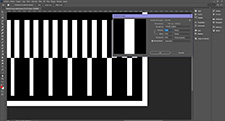
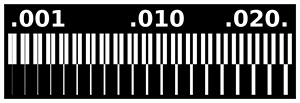
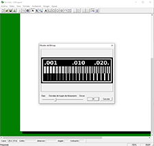
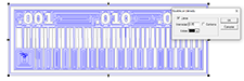
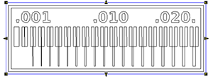
I have downloaded "Rule design file" to know what tolerances and distance should be optimal. I will export in PNG to take it to Photoshop if I have to make any modifications, for example, reduce the milling area. It’s also important that the resolution is 1000 and the color mode is grayscale. Then I’ll save it as a file. bmp so you can import it to Dr. Engrave.
The tracks must be equally measured in the digital design and when it is to be manufactured in the milling machine. Thus avoid future mistakes when welding and programming.
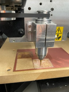
I will leave the milling machine ready for when I have the design ready and the defined parameters I can send to print. Here are the following steps:
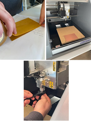
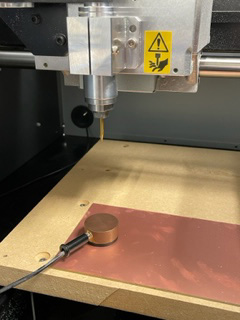
- Place double-sided tape so that the material does not move and place it on the work table.
- We turn on the machine.
- We place the cutter in this case will use for engraving a conical cutter of 30 degrees. Placing the cutter on the head by tightening it with the wrenches.
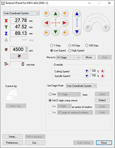
With the Roland V Panel program:
- We open the VPanel program, they are the controls to be able to move the axes of the milling machine. We calibrate the shaft (XY). Bring the strawberry to the bottom left corner. Using the green and red arrows. "Set origin" XY, Apply.
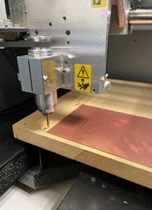
- Calibrate the axis (Z) by placing the sensor until the cutter detects it. "Set Z origin using sensor.Detected. Then remove it.
Many things must be taken into account for proper manufacturing.
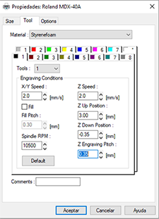
Filling intensity, Z engraving (Z Engraved Pitch) and Z down position are important adjustments that affect the quality of the engraving.
Fill intensity (Fill Intensity) refers to the amount of material that is removed from the object during the engraving process. A high fill intensity value means that a large amount of material will be removed, resulting in a deep engraving. On the other hand, a low fill intensity value means that a smaller amount of material will be removed, resulting in a more superficial etching. In general, it is recommended to use a high fill intensity for soft materials, such as plastics, and a low fill intensity for harder materials, such as metals.
The "Z down position" setting controls the initial position of the engraving tool relative to the surface of the material. A high Z down value means that the engraving tool will start recording from a higher position, while a low Z down value means that the engraving tool will start recording from a lower position. This adjustment is important to prevent the engraving tool from hitting the material at the beginning of the engraving and to ensure uniform engraving.
Z-engraving (Z Engraved Pitch) refers to the depth of the engraving on the Z-axis, which is perpendicular to the surface of the object. It is essential to control the depth of engraving and achieve the precision of engraving work. If the engraving value in Z is too large, the engraving will be too deep, whereas if it is too small, the engraving will be too superficial. It must be adjusted according to the material and the desired depth.
The design is imported as a block and must be separated, for that right click on the object and select "drop polygons". This is done to have separately the inside part to engrave and the outside part to cut, then you have to select all the curves of the inside and recreate the group of polygons. First, the engraving will be performed and for this the option of creating a path is selected giving a milling width of 0.15mm (taking into account the width and angle of the conical cutter).
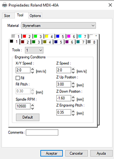
Print properties, we select the step and the depth of the step. To perform the engraving I have selected a depth of 0.35mm. And filling intensity 0.15. Rpm: 10500
For the right click cut deactivate filling, then you can "separate polygons" and only select the edge of the plate.
In print properties we will select the appropriate parameters. For the depth cut is -1.6 mm with 0.35 mm passes.
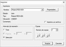
File Print.
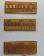
The values I have set are wrong because after measuring the roads, they do not measure the same as in digital design, it is important to have it well and then weld properly and there are no errors.
The second attempt change the values. To perform the engraving I selected a depth of -0.10mm. Pitch 0.05 and fill intensity 0.1. Rpm: 10500 . For depth cutting is -1.6 mm with 0.35 mm passes.
The values are still wrong. The size of the tracks is close to the size of the digital design, but it is still small.
The third attempt change the values. To perform the engraving I selected a depth of -0.12mm. Pitch 0.10 and fill intensity 0.12. Rpm: 10500
The values are still wrong. The size of the tracks is close to the size of the digital design, but it is still small. The digital design tracks measure 0.53mm and this third internal measures 0.50mm.
I am struggling to understand what appropriate values to put and I can not understand very well the functioning of the values I have to put. With which, my attempt to continue advancing in making my pcb, welding and then programming it, will make you have very fair time, and sure that in some things will not give me time.
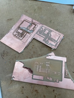
Even so, I have continued ahead, and I decided to manufacture my PCB, since the last values were approaching the measures I need.
First I opened the Eagle file where I have my PCB designed. I will export in PNG to take it to Photoshop if I have to make any modifications, for example, reduce the milling area. It is also important that the resolution is 1000 and the color mode is grayscale. I will then save it as a file. bmp so I can import it to Dr. Engrave. Considering everything I learned I made my pcb.
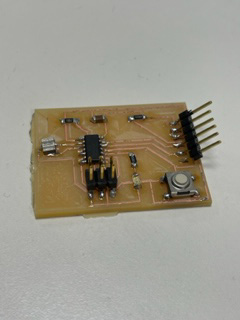
With values of: To make the engraving I selected a depth of -0.15mm. Pitch 0.05 and filling intensity 0.08. Rpm: 10500 The result at the second attempt was good and after evaluating it I started to select my components to weld it.
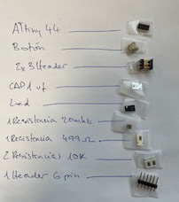
- ATtiny44
- Button
- 2x3 header
- CAP 1 uf
- 1 Led
- 1 crystal 20mhz
- 2 resistance 499
- 1 resistors 10k
- 1 header 6 pin
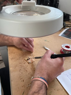
Then I started welding, I never did. It’s very difficult when you have no experience, welding such small things and being very precise has been a challenge for me. I was also very nervous as I saw that I would not get to complete the whole week I had to calm down to weld well. But I did or I think I did. I liked the experience.
Download
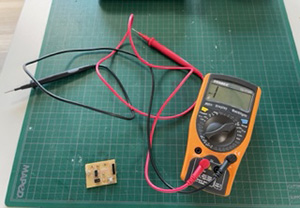
Testing for continuity check
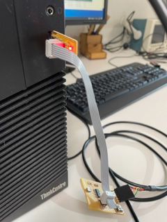
Then I connected the ISP to the attiny44 via an isp key and in turn an FTDI cable to the computer. The ISP serves as a bridge to be able to program my pcb. It is important to know how to lay the ISP cable properly in order to connect ground to ground. On the other hand, the ISP board must also be configured and programmed to "transfer" the programming to the subsequent PCBs. As I have already mentioned in the FabLab there is an ISP where the J1 jumper is unsoldered. That means that the ISP is already programmed and ready to bridge to other PCBs.

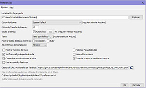
Then I'm going to Arduino and I'm going to put some simple code to program it. On the internet I can find a link to "install" ATtiny microcontrollers in the Arduino libraries under Preferences
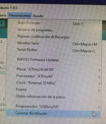
Select, in Boards Manager attiny and install it. Then, under Tools (Tools) select ATtiny44 as processor and USBtinyIPS as programmer.
Under Tools select the appropriate board, processor, Clock and port so that you can program correctly.
Save Bootloader ("Burn Bootloader") to tell USBtinyISP and PCB to program with Arduino.
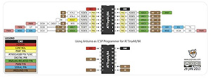
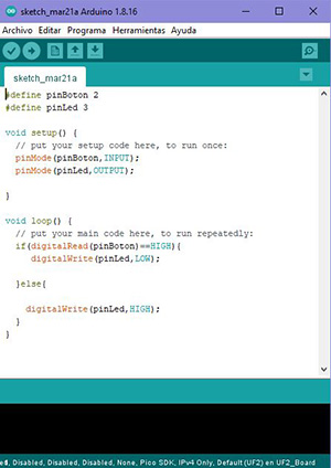
See the ATtiny schematic below for each pin number connection in Arduino language. My schematic says my INPUT (button) is pin 2 and the OUTPUT (LED) is pin 3.
Insert this code into Arduino with the help of the gpt chat
Everything is correct, but I can't program it, I don't know what's wrong. My instructor has told me that maybe it's because the soldering of some component is wrong. It's the first time I've soldered something... Next time I will take this into account.
The instructors at the regional interview told me that I didn't need to do it as I have already tried it and next time I will do it better.
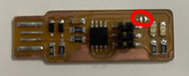
I have made another PCB with a Xiao rp2040 to be able to make the demo video and so I can also use this board for the "input" week. In the Input week I will show how I make the board. I have uploaded the code with the help of ChatGPT, with the correct parameters using the port, and the board correctly. Here I show the video.
Below, I show how I have continued to develop the challenge in the Input Device week and so it will work for me this week as well. Input Device Week