WEEK 11: Input devices
INDIVIDUAL ASSIGNMENTS
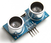
In this exercise you will learn how to insert input devices into a microcontroller. I will use this type of sensor for my final project. An ultrasonic sensor has been chosen to carry out the work, it is a device for measuring distances. Its operation is based on sending a high frequency pulse, not audible to humans. This pulse bounces off nearby objects and is reflected back to the sensor, which has a microphone suitable for that frequency. Finally I am going to do some tests with the reading of analogue and digital signals from this input device.

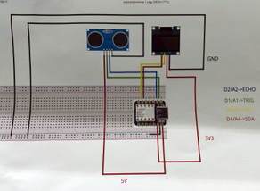
I have based myself on the diagram in the image below to find out how I should connect the tracks.
Eagle software has been used to start designing the exercise platform. The board will have a Xiao rp2040 processor, a sensor and resistor to make it work properly. This program has an extensive library of components and facilitates the design and fabrication of the board. It is necessary to load the library provided by FabLAB to add the components we are working with. I also had to find the footprint of the Xiao rp2040 in order to add it to the library.
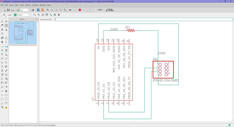
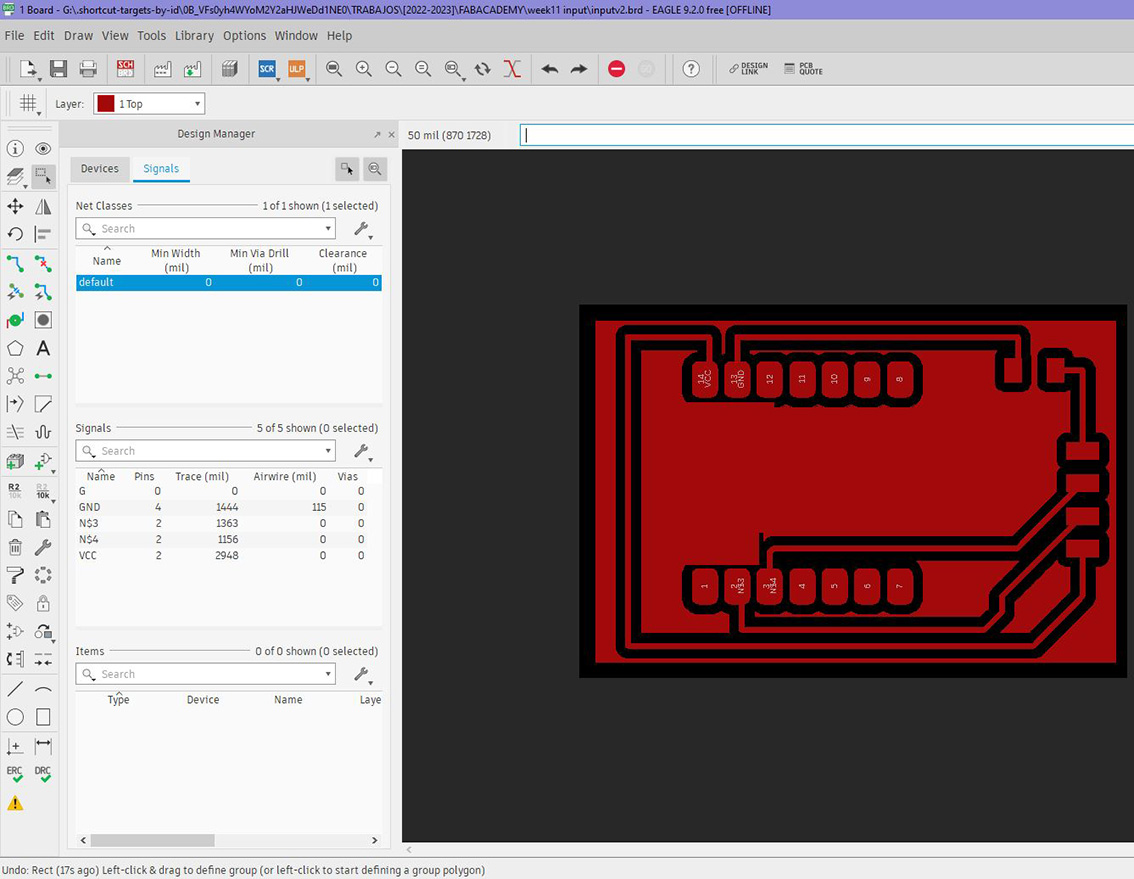
Once you have finished the schematic and checked that everything is OK. Then press the "SCH/BRD" button, Eagle will prepare the board layout. Once your schematic board is displayed, all the components and their connections will be displayed randomly, so all the connections must be arranged and made so that there are no intersections and the space between them is not too small. This has been a complicated job as there are several interconnected components and I had to do several tests until I have successfully completed the schematic.
Now it only remains to export the file in .png format with high quality and in monochrome colour, it is necessary to hide all the layers except the connections and contact pins of the components.
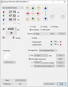
Before starting to manufacture, the machining tool must be selected and the machine calibrated (xyz). For this step, the steps explained in the electronic manufacturing exercise were followed, using the V-Panel software. The milling cutters used are 0.1 mm, cylindrical for cutting and conical for engraving.
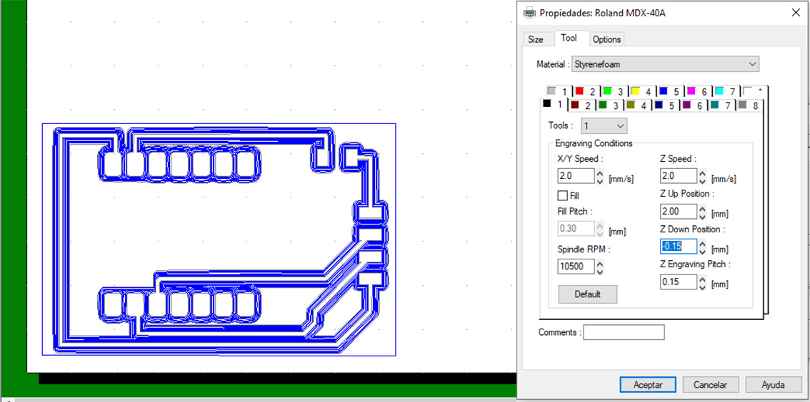
Then you have to import the design into the DR Engrave program, set the appropriate dimension and prepare the paths as in the previous exercise.
I used the values -0.10 mm for engraving and 1.60 mm for cutting. The other parameters of rotation speed and displacement are the same as in previous exercises. Once the engraving has been launched, the outer cut has to be launched and wait for it to finish.
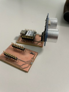
The following picture shows the final result of the board before soldering. It has been cleaned to remove any copper residue that may interfere with the connections.
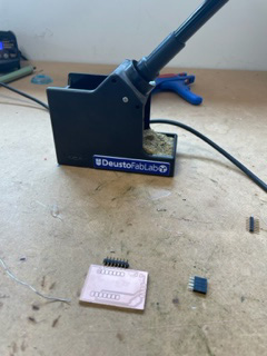
I had to remake the board as the tracks were narrow and when soldering I had a short circuit. In the picture I show the first board and the second one improved and soldered with the components.
Now it's just a matter of creating a code and programming the board. I hope it works. I don't know if I have done well the schematic in Eagle, the only thing I am sure is that it is well soldered and it won't short-circuit.

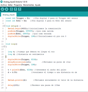
Below, I show the code I used to program on my PCB. Aided by the chatGPT. This code is an example of how to use an ultrasonic sensor to measure distances and display the results via serial communication. Below, I will explain step by step how it works:
First, you define two constants: Trigger and Echo, which represent the digital pins used for the trigger and echo of the ultrasonic sensor. In this case, D1 is assigned to the trigger pin and D2 to the echo pin.
In the setup() function, the initial configuration of the program is performed. Serial communication is started at a speed of 9600 baud using Serial.begin(9600). In addition, the mode of the Trigger and Echo pins is set: the trigger pin is configured as output (pinMode(Trigger, OUTPUT)) and the echo pin as input (pinMode(Echo, INPUT)). Finally, the initial state of the trigger pin is set to low (digitalWrite(Trigger, LOW)).
The loop() function is the main loop of the program, which runs continuously. This is where the distance measurement occurs. Two variables are declared: t to store the echo duration time and d to store the calculated distance in centimeters.
First, a 10 microsecond pulse is sent to the trigger pin to trigger the ultrasonic sensor measurement. This is done by setting the trigger pin high (digitalWrite(Trigger, HIGH)) and then low (digitalWrite(Trigger, LOW)). Next, the pulseIn() function is used to measure the time it takes for the echo to arrive. You pass the echo pin as a parameter and specify that you want to measure the pulse duration on high (pulseIn(Echo, HIGH)). The result is stored in the variable t.
Once the echo duration time is obtained, it is scaled to a distance in centimeters by dividing t by 59. This scale may vary depending on the speed of sound in the environment in which the sensor is being used.
The distance value obtained is then displayed using the Serial.println(d) function. This will send the distance value over serial communication so that it can be displayed on a serial monitor.
A delay of 100 milliseconds is added using delay(100) before the main loop repeats.
In summary, this code configures an ultrasonic sensor, measures the distance using ultrasonic pulses and displays the results in centimeters via serial communication.
The code can be found at Interface & Application programming where it can be downloaded.
GRUPAL ASSIGNMENTS
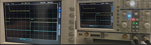
One of the biggest advantages of an oscilloscope is the ability to measure high-frequency signals. To get more information about the speed of the incoming signals, we measure an arduino program.
Since we want to show the data from our board and sensor on an oscilloscope, below are some images showing the data from the HC-SR04. I recorded the sensor values at different distances. The following three images show different distances measured by the sensor.