
The home stretch is approaching. I will dedicate to the organization and description of the final project, which I will describe step by step. Maybe later I will make some changes if I have some problems or if I decide to change something.
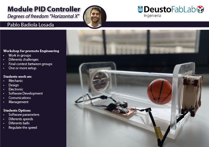
My final project is an educational project for teaching and research. A control platform D.O.F Degrees of freedom "horizontal x". The degree of freedom can be thought of as the number of independent ways an object can move horizontally, left to right or front to back. It is ideal for introducing students to the fundamental and intermediate principles of controls. The university asked me to do this, so that I can teach everything I learned to the students.
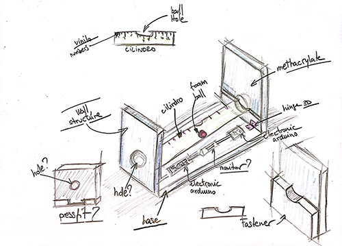
It consists of:
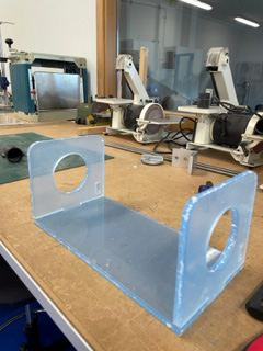
- A support base to the structure, some fixing walls that have a hole in them where the fans will go.
- Controlling the speed of the fans, they will move the ball in "X axis" according to the power indicated on them.
- The power of the fans will be controlled by a monitor that will be connected to the Arduino, one at each end for each fan.
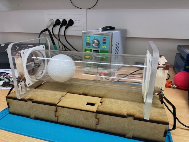
- A glass cylinder where the fans are connected at the ends. Inside the cylinder there is a foam ball that will move in "X axis" according to the power of the fans desired.
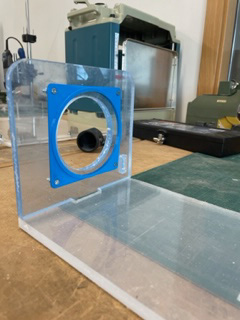
- The structure will be of methacrylate of about 12mm thick and will make "pressfit" to be able to assemble the pieces so that they fit well. I’ll use the CNC Milling Machine to do it. I will also place some hinge designed in 3D printer if necessary to better hold the base with the walls.
- I will use the Laser Cutter to cut the cylinder as long as you need.
| Bluethoot HC-06 FC-114 | Deusto FabLab | |
| Screen: OLED | Deusto FabLab | |
| Distance Sensor: VL53L0X | More Info | |
| 2 Fans | More Info | |
| Electronics Components: Headers, pins, resistances, microcontroller | Deusto FabLab | |
| Had of Methacrylate | More Info | |
| Methacrylate, Vinyl, Filament for 3D printer, Tools | Deusto FabLab | |
| Foam Ball | Shop | |
| Cables | Deusto FabLab |
The following shows how I have been carrying out my final project. I will be describing the parts of my final project along with the information.
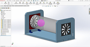
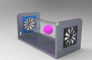
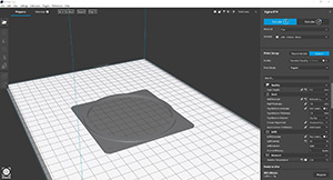
STRUCTURE
I have made in Solidworks all the parts of my project and then I have created an assembly. I have also made a render with Keyshoot.
I have taken into account the measures that I have to use for:

Download
Once created, I will start to prepare the corresponding file to be able to manufacture it in the milling machine.
Download
These are the steps I have done to make the structure, based on Computer-Controlled Machining week.
I have converted the parts I need to make into DXF so I can open a Vcarve file with those files and send it to the milling machine.
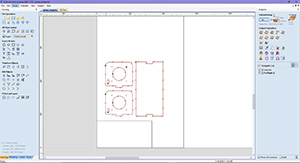
Once the file is created, we send it to the milling machine via USB.
Here I show a video of how the pieces are made. I have followed the steps mentioned in week 7, Computer controller machining. The result has been very good.
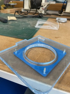
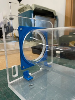
3D PART: CLAMPING
I have made a 3D part to hold the cylinder with the structure and I have taken into account the measurements so that the holes match. I have made it in Solidworks and then I have saved it in STL to be able to take it to the BCN printer.
I have set the right values in the BCN cura so that the part comes out very well. Indicating the temperature in the nozzle and in the plate, the speed, the corresponding extruder, the layer height, the filling... etc... I have taken into account the tolerances so that the methacrylate tube fits perfectly with the piece. It is very important.

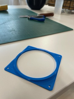
Once it is done, I will place it in the structure of my project and test that everything fits well and that the tube is well fastened.
Download
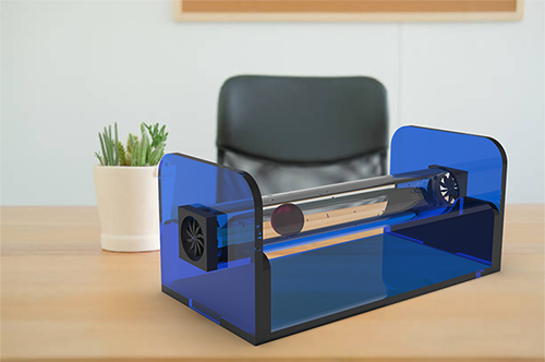
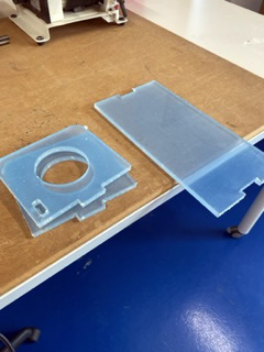
METHACRYLATE TUBE
I have chosen a methacrylate tube. I was in doubt whether to choose a glass tube but in the end I think it will be more resistant and cheaper the methacrylate tube. I have started to search and think about how to get it and I got it in "Amazon".
Characteristics:
This is the final result for now.
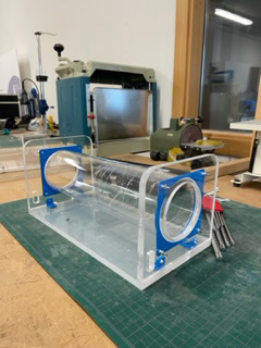
BALL
A foam rubber ball with a diameter slightly smaller than the inner diameter of the tube.
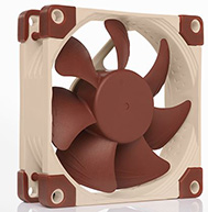
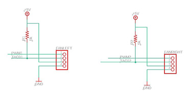
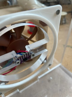
2 FANS
Here I show the fans that I am going to use. They will be placed at each end of the methacrylate tube to move the ball.
Characteristics:
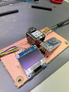
ELECTRONIC COMPONENTS
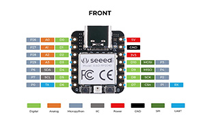
MICROCONTROLLER
The Arduino RP2040 is a microcontroller board developed by Arduino in collaboration with Raspberry Pi. It is based on the Raspberry Pi RP2040 microcontroller, which features a dual-core ARM Cortex M0+ processor and SRAM 264KB.
SENSOR
Here I show the sensor I am going to use. It is a sensor that will measure the distance where the ball is. I leave a PDF to download the information and characteristics of the sensor.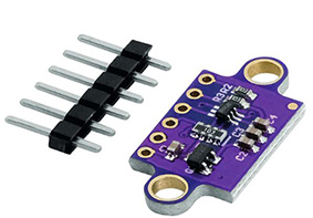
Download
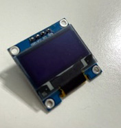
OLED SCREEN
OLED displays are characterized by high contrast, minimal power consumption and good image quality. The 0.96" SPI SSD1306 oled display has a resolution of 128*64 pixels, allowing to control each pixel individually and display both text and graphics. In addition to being OLED type does not need backlight (Backlight) as the LCD, which makes its power consumption is much lower and increases its contrast.
Characteristics:
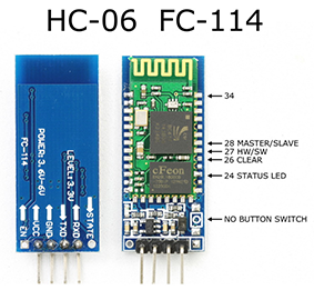
BLUETHOOT
The Bluetooth Module HC-06 is a device that supports wireless connections through the "Bluetooth" protocol. It can behave as a slave or master, which is used to listen for connection requests and to generate connection requests.
Characteristics:
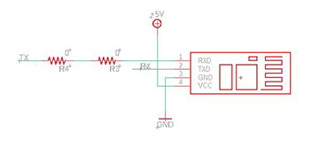
With all this information I will start to create the sketch in Eagle using the datasheet to guide me on the components and correctly join the vias and connections.

Next, I show the parts of the pcb sketch. It is important to have it clean and easy to understand. Without so many connection lines so as not to confuse us.
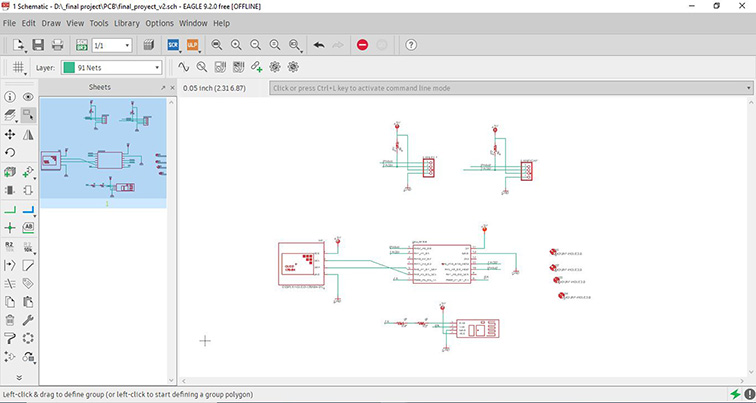
Download
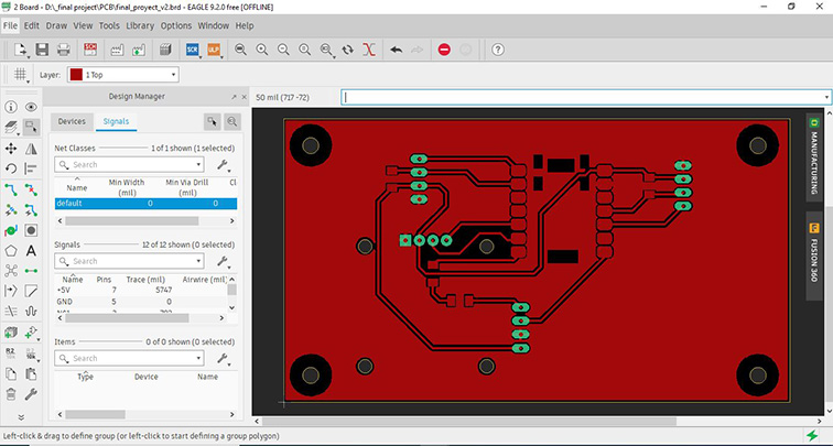
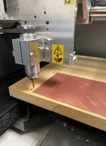
Once the connections have been correctly made, I will start milling the board.
I will leave the milling machine ready for when I have the design ready and the defined parameters I can send to print. Here are the following steps:
- Place double-sided tape so that the material does not move and place it on the work table.
- We turn on the machine.
- Placing the cutter on the head by tightening it with the wrenches.
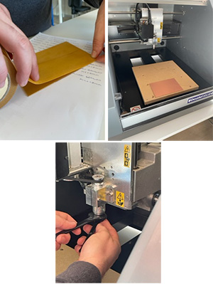
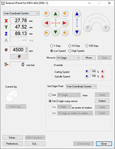
With the Roland V Panel program:
- We open the VPanel program, they are the controls to be able to move the axes of the milling machine. We calibrate the shaft (XY). Bring the end-mill to the bottom left corner. Using the green and red arrows. "Set origin" XY, Apply.
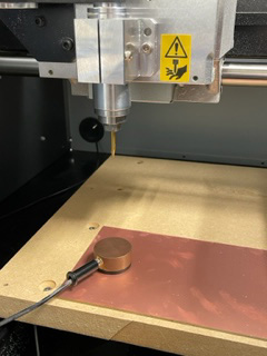
- Calibrate the axis (Z) by placing the sensor until the cutter detects it. "Set Z origin using sensor. Detected. Then remove it.
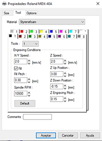
Many things must be taken into account for proper manufacturing.
Filling intensity, Z engraving (Z Engraved Pitch) and Z down position are important adjustments that affect the quality of the engraving.
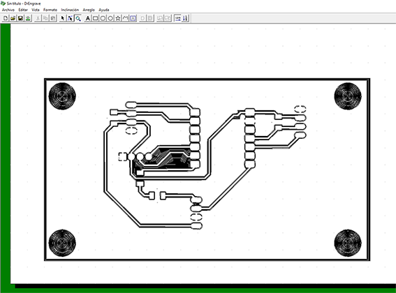
The design is imported as a block and must be separated, so right click on the object and select "separate polygons". This is done to have separately the inner part to engrave and the outer part to cut, then select all the curves of the inner part and recreate the polygon group. First the engraving will be done and for this we select the option to create a path giving a milling width of 0.1. Print properties, we select the step and the depth of the step. To perform the engraving I have selected a depth of -0.15mm. And fill intensity 0.1. Rpm: 10500
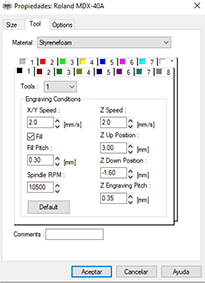
In print properties we will select the appropriate parameters. For the depth of cut is -1.6 mm with 0.35 mm passes.
Download
Once done, I will solder all the components and I will make sure with the multimeter that there is no short circuit. I will also place the sensor on one side of the wall of the structure and on the same axis as the ball, so that it can better capture the signal.
Once welded correctly, I assembled the structure and placed the ball inside the tube.
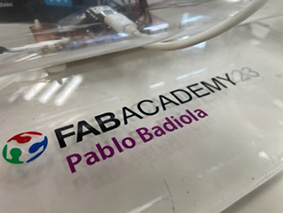
I am going to use vinyl to place it on the base of my project, I have thought of putting the Fab academy logo and my name. I vectorized the logo and with Rhino I created the letters and prepared the design to send it to the vinyl cutter. Then I selected the parts of the design and sent them to the vinyl cutter changing the vinyl according to the colour. Once cut and peeled, I will place the vinyl on the base.
I will follow the same steps as in previous weeks (Week 3).
Download

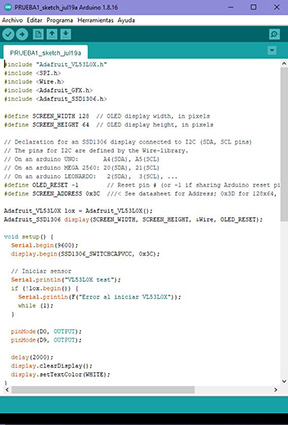
Next I will start creating the code in Arduino.
I have started by installing in the library the following libraries that are needed to be able to realize the code. Libraries are essential because they encapsulate the code needed to interact with the devices and components to be used in the project. They simplify programming and allow developers to focus on the logic of the project. I explain each of them below.
Once the libraries are installed, you can use them in your code to interact with the VL53L0X sensor and the OLED display easily and efficiently.
With the help of my instructors guiding me, internet research on code related sites and documentation I have created the following individual codes so that I can later merge them into a single code for the project.
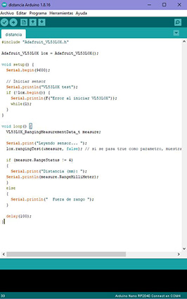
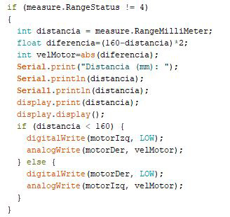
The distance code: For the sensor to read the distance of the object.
The operation of the code is as follows:
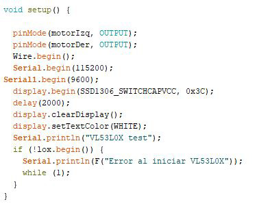
In the setup() function, serial communication is started at a rate of 9600 baud using Serial.begin(9600). Then, the VL53L0X sensor is initialized with lox.begin(). If the sensor does not initialize correctly, it displays an error message on the serial monitor and enters an infinite loop with while(1).
In the loop() function, a variable measure of type VL53L0X_RangingMeasurementData_t is declared, which is a structure used to store the measurement data of the VL53L0X sensor.
A ranging measurement is performed using lox.rangingTest(&measure, false). This gets the measurement from the sensor and stores it in the measure structure. The second function parameter (false) indicates that we do not want to see debug data on the serial port.
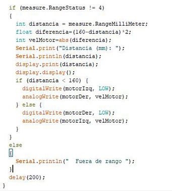
It checks if the status of the measurement is different from 4 (measure.RangeStatus != 4). A status of 4 indicates that the measurement is outside the valid range of the sensor.
If the measurement is within the valid range, the distance in millimeters is displayed on the serial monitor with Serial.println(measure.RangeMilliMeter).
If the measurement is out of range, a message is displayed indicating that it is "Out of range".
The loop() loop repeats every 100 milliseconds (delay(100)).
This code is useful for testing the operation of the VL53L0X sensor to verify that it is measuring distances correctly.
The code for OLED.
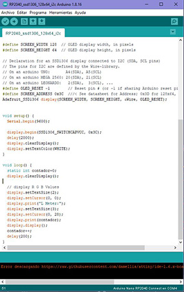
This code is an example of how to use a monochrome OLED display based on the SSD1306 controller. The display has a resolution of 128x64 pixels and communicates via I2C (Inter-Integrated Circuit) with the Arduino microcontroller. This display is sold by Adafruit and is compatible with the "Adafruit_SSD1306" library.
This example is a counter displayed on the OLED display. Every 200 milliseconds, the counter is incremented by 1 and displayed on the screen. The OLED display is cleared and updated on each iteration of the loop() loop.
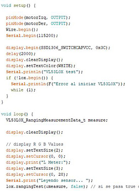
Once I have these two codes I will try to put them together into one code. This code combines both functionalities. The VL53L0X sensor measures the distance and is shown on the OLED display along with a counter that is incremented at each iteration of the loop() loop.
This is the first test I have performed to see how it works. 😂 Because one of the fans was badly welded and also in the code it had errors.
I will keep trying and researching
Clearly it doesn't quite work yet. So I am going to improve the code so that the distance is displayed on the screen. I have also added in the code that once the ball gets close to a fan it automatically turns off and turns on the other fan at the end making the ball go from one side to the other showing the distance on the screen.
The code is shown below.
Below, you can see in the video how my project behaves with the updated code. This time it works better.
The next step I have done is to add a "Serial1" function in the code so that the bluethoot can be connected and the distance can be displayed on a laptop or tablet as a reading list.

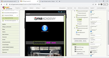
Once I get it done I will design a simple interface to visualize it on the Tablet and make it more attractive. I will design the interface in a web called app inventor where I will have a lot of tools and options to design. It is an easy to use program if you don't have knowledge about it. It is intuitive and together with information and tutorials that I have been looking for I have learned and I have been able to create the interface. Now I have it all clearer.
These are the steps I have followed:
1.- go to the MIT app inventor page and create an account. Then you create a project and step by step you design boxes, buttons, images, text...
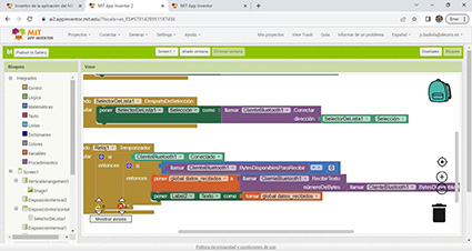
2.- design by blocks the bluethoot code and the option of how to receive data from the bluethoot.
3.- Download the MIT AI2 Companion application to access the interface created and using the QR code that is generated, you can access the interface.
4.- Connect and pair the bluethoot of the tabet with the bluethoot of the project and the interface created will appear.
It came out as expected. I just need to change the ball for a lighter one to make the movement better. In the following video I show it. 😊
Download
SLIDE SHOW
Download
FINAL VIDEO
My final project is an educational project for teaching and research. A DOF control platform "Horizontal x" degrees of freedom. The degree of freedom can be considered as the number of independent ways in which an object can move horizontally, from left to right or from front to back.
The ball approaches one fan it automatically turns off and turns on the other fan at the end making the ball go from side to side showing the distance on the OLED screen and the possibility to connect by bluethoot from any device also showing the distance the ball travels.
LAST CHANGES
After the presentation of my project, I had to make some changes.
Neil told me that I need to control the distance the ball travels and also hide the wires of the electronics.
So I have made this structure in which you can put the wires and not see them and at the same time you can see the OLED screen from a slot that I have made. Also easy to disassemble and to be able to manipulate the components. The structure I have made it in DM wood and laser cut, it has been great! 🙂 🙂
Once the structure was assembled, I started to look at the Arduino code and think about how to do what I have been asked to do.
First I have to find a ball that covers the diameter of the tube, because being smaller, the air generated by the fans is wasted. I have gone all over town to find a suitable ball.
One fan will be between 0 and 255 and the other between 255 and 0. One fan will turn off when the ball is on the opposite side of the fan. If I want the ball to be in the middle both fans will be pushing and running both.
Depending on the distance indicated the fans are regulated making the ball go to the indicated point.
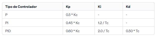
The code works, now it only remains to calculate the appropriate PID parameters to regulate the power so that they stay in a desired point. So the ball will not be back and forth as before, but it will be regulating the power. I have to get it to read the data well and look for the values of kp, ki and kd (proportional, integral and derivative value). I have followed the next steps of the following method, below I show what I have done:
The Ziegler-Nichols method is a classic approach to PID controller tuning that involves performing tests on the system and using the results to determine the controller parameters. Here I show you the steps to apply the Ziegler-Nichols method:
Set the controller to Proportional (P) mode:
Starts by disabling the Integral (I) and Derivative (D) terms of the PID controller. Sets the Proportional (P) term to a low initial value.
Gradual increase of the Proportional (P) term:
Gradually increase the value of the Proportional (P) term until you observe sustained oscillations in the system output.
Determine the critical gain and critical period:
The critical gain (Kc) is the value of the Proportional (P) term when sustained oscillation is reached.
The critical period (Tc) is the period of time between two consecutive oscillations.
Calculate the controller parameters:
Using the values of the critical gain and critical period, you can calculate the PID controller parameters according to the following table:
Once I calculated the PID controller parameter values, I enabled them in the controller and tested the system to verify its performance. If necessary, make additional adjustments to the controller parameters and repeat the testing process until satisfactory performance is achieved.
Below, I show the code performed:
Download
FINAL VIDEO
CONCLUSION
I have had a hard time getting the ball to not oscillate so much and I think the values I have set (PID) are adjusted as best as possible. It takes a little while to get into position but little by little it is getting to the right spot. I am very happy with the result because it is all new to me and it has cost me a lot to do it given my knowledge. But I have learned a lot.
From any device via bluetooth you can insert the desired distance and the ball gradually goes to the indicated point. In this case since I don't have a tablet I have installed the bluetooth program on my laptop.