WEEK 10: Mechanical Design & Machine Design
GRUPAL ASSIGNMENTS
This week's group homework can be found on the page:
Read More
INDIVIDUAL ASSIGNMENTS
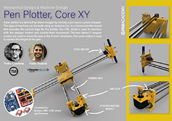
The next challenge these days is to design a team machine including mechanism, drive, automation and application. Build mechanical parts and operate them manually and of course document the group project and document everyone's individual contribution. Also drive and automate the machine and make a video of it. Below I show my individual contribution.
- Design and test machine table fixtures
- Design inclined table to support the machine
- Design safety cover for the machine
- Create initial test Gcode
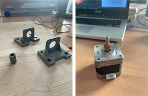
- Design 3D model stepper motors mounts with endstops (EndX, EndY)
- Parts fabrication: 3D printing all parts, Laser cutting machine cover
- Machine building
- Ideas to improve designs
- Final Video
- Poster the machine
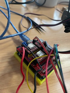
My teammate is Pedro Candeias, he lives in Porto and is doing the Fab Academy at FabLab León. We decided to get together there and start assembling the machine. Our aim is to make it work, to assemble the electronics and the machine. Afterwards, the design, the details and the parts that we need to make, we will each make them in our corresponding FabLab and we will send each other the files via drive to be able to share them. I will be in charge of designing it, manufacturing it and verifying that the parts are correct, as my partner has worked on the beginning of the assembly of the machine, as we are aware that it is impossible to do what we want in a weekend. So once it is well verified I will share the files ready for Pedro to build it. At the weekend I arrived in León with my instructor and we went to the FabLab to meet my colleague and to organise the work we were going to do over the weekend. Together we finished assembling the machine and the details.
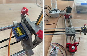
We saw that it worked and that the axles moved correctly.
Then we put a sheet of paper and a marker pen and the drawing was a little bit shaky because when the z-axis was lowered the marker pen moved a little bit and made some damage in the drawing. But we are still happy with the work. My partner is very intelligent and I am learning a lot from him.
We noticed when we tested it that when it drew, it drew at a slant. My instructor suggested that maybe it was because the ropes were not sufficiently tensioned and the axes were not perfectly aligned. We tried to tighten it and correct this problem and also to think about what we could do to tighten it properly. Even so, by stretching it a little more and correcting this problem, we tried it and then the machine continued to make the inclined drawings. My colleague solved it because he realised that the machine was configured with 3 axes for X,Y,Z but it didn't need three axes. You need two for X, Y and Z and for Z we already had a servo motor which is in charge of driving the Z axis.
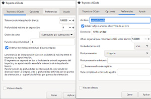
Together we also thought of doing a different drawing. The Mandalorian. With InKscape I made the vectors and I was testing how to save it in gcode.

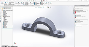
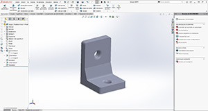
A PIECE TO HOLD THE MACHINE ON THE WOODEN BASE.
I have designed a piece to hold the machine on the wooden base because we want to put the machine inclined. Below I show the steps I follow to get the desired and suitable piece for our project.
I wrote down the measurements and distances from one of the parts of the machine to the base of the board to know what measurements I should take to create the piece. I based myself on a part in the FabLab and adapted the correct measurements.
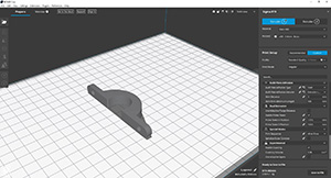
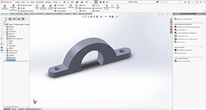
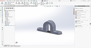
FIRST ATTEMPT:
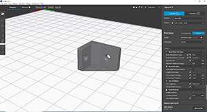
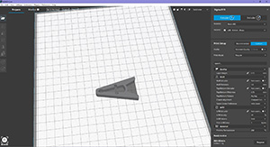
I have designed it in solidworks making a sketch with the appropriate measurements and I have extruded it about 10mm and I have saved it as STL and then in the BCN Cura software I have sent it to print to the 3D printers in gcode format.
With the right parameters I started to test what is best to make the part strong and send it to manufacture.
I had complications because it wouldn't let me go forward when I inserted the filament into the BCN.
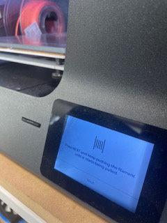
I asked mattermost and Adrian told me that it is possible that the sensor does not recognise the filament. ☹️ I turned the printer off for the third time, turned it back on and tried to put the filament in again and got lucky because the sensor was able to identify the filament. What a scare! So I was able to print the first test, thank goodness.
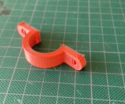
This result is not valid first because I put support in the holes as I thought I would need it, but Pedro told me that when there are curves there is no need. So I made it again without support with the comparison of the one with support.
I also tested for strength and found that the density I chose was too low, 25% density. With a little force I broke the piece.
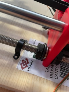
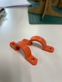
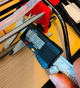
The height of the piece is fine, but after Pedro made it and put it in the right place, we saw that the diameter of the piece is too big, and we need a smaller one to get a better grip. I also have to change the density of the piece and it has to be bigger.
So I decided to change the dimensions, Pedro sent me this photo with the diameter to adapt it better. 9,68mm.
SECOND ATTEMPT:
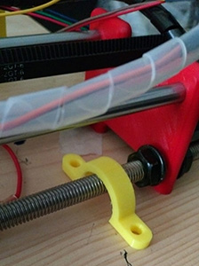
I modified the dimensions and measurements of the part with a diameter adapted to those measurements. I rounded the measurement and put 10mm diameter. The holes for the M5 screws. I'll save it in STL to send it to BCN Cura and I'll print it to see how it does. I hope it works and fits better. I won't finish until I get it.
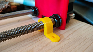
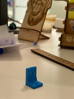
THIRD ATTEMPT
I have made a better piece. I think it fits better and will hold better.
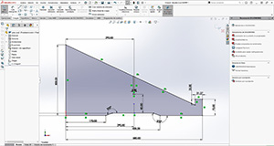
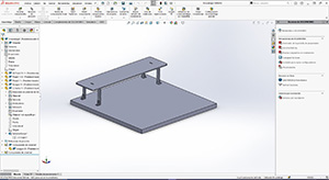
DESIGNING A STRUCTURE TO SUPPORT THE MACHINE BASE
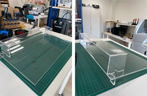
Another of the things that I have taken care of is to make a structure to support the machine and to make it inclined. I thought of making it out of methacrylate as part of the machine will also be covered with a structure to protect it a bit and it will be made of methacrylate.
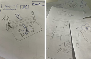
I started by making sketches and imagining how the structure would look like.
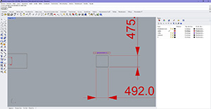
I started to design in solidworks the different parts of the base, the legs and the cover of the machine. I decided to make it in 5mm methacrylate on the laser cutter using presfit, leaving a small hole on the sides for the cables to pass through.
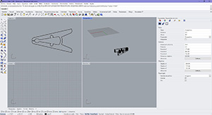
I then saved it as a DXF so I could send it to Rhino to be able to manufacture it on the Laser.
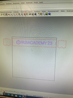
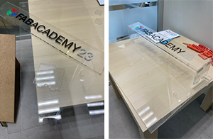
I have also vectorised the Fabcademy logo to place it as a vinyl on the cover.
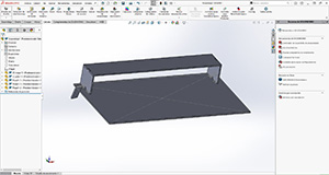
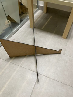
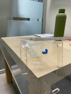
We realised that maybe the machine was going to be too heavy for the plexiglass to hold. So we decided to reuse the board we had from the beginning and reuse it. So I made some inclined legs mounted in the shape of a cross and inclined for the wooden board which will be our base for the machine.
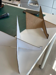
First on the laser cutter I made a couple of prototypes with different materials to see how it would look.
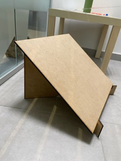
And then I made it in real size and sent the files to Pedro so he could make it.
I redesigned the cover of the machine as the table is the same width as the machine so the previous design does not work. I have to redesign the sides of the cover and take measurements of the machine width and height to know how to place the ends. So I changed dimensions and measurements and adapted the design better. Also with holes to place the hinges to join together with the base. I also took into account the file measurements of the machine parts, measuring in the files to know exactly what measurements to choose.
A HINGE TO FASTEN THE COVER TO THE WOODEN BASE.
Make this part in solidworks to attach the structure to the wooden base. Then create an STL to send it to print to the BCN 3D machine. I have to take into account the width of the structure.
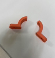
A CLIP TO HOLD THE T-SHIRT ON THE WOODEN BASE.
Download
POSTER MACHINE
I have done it in illustrator