11. input
Ok, hard times....design the board following the example from repository....made it...no errors...programmed it...didn´t work.
Now, i´m doing a new one....with 2 resistors less....let´s see what happen...
Didn´t work either....maybe the thermistor is burnt.
I will try again with a new thermistor and a new board....
New update
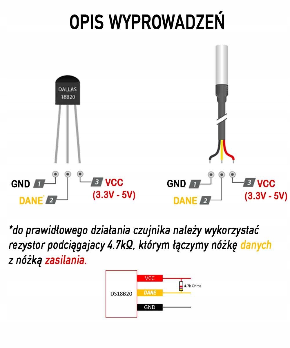
I buy a new sensor, a ds18b20, and this is a new begining.
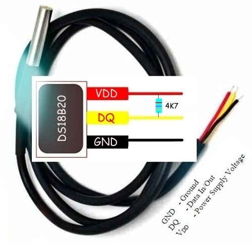
Ds18b20 datasheet.To make it work, i need to make a board with a pull up resistor between the signal cable and the VCC.
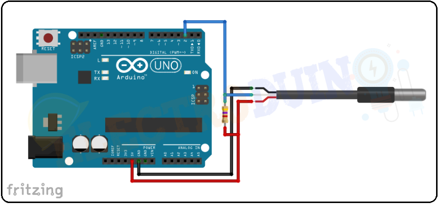
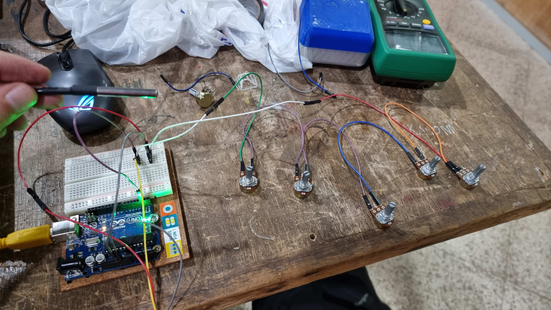
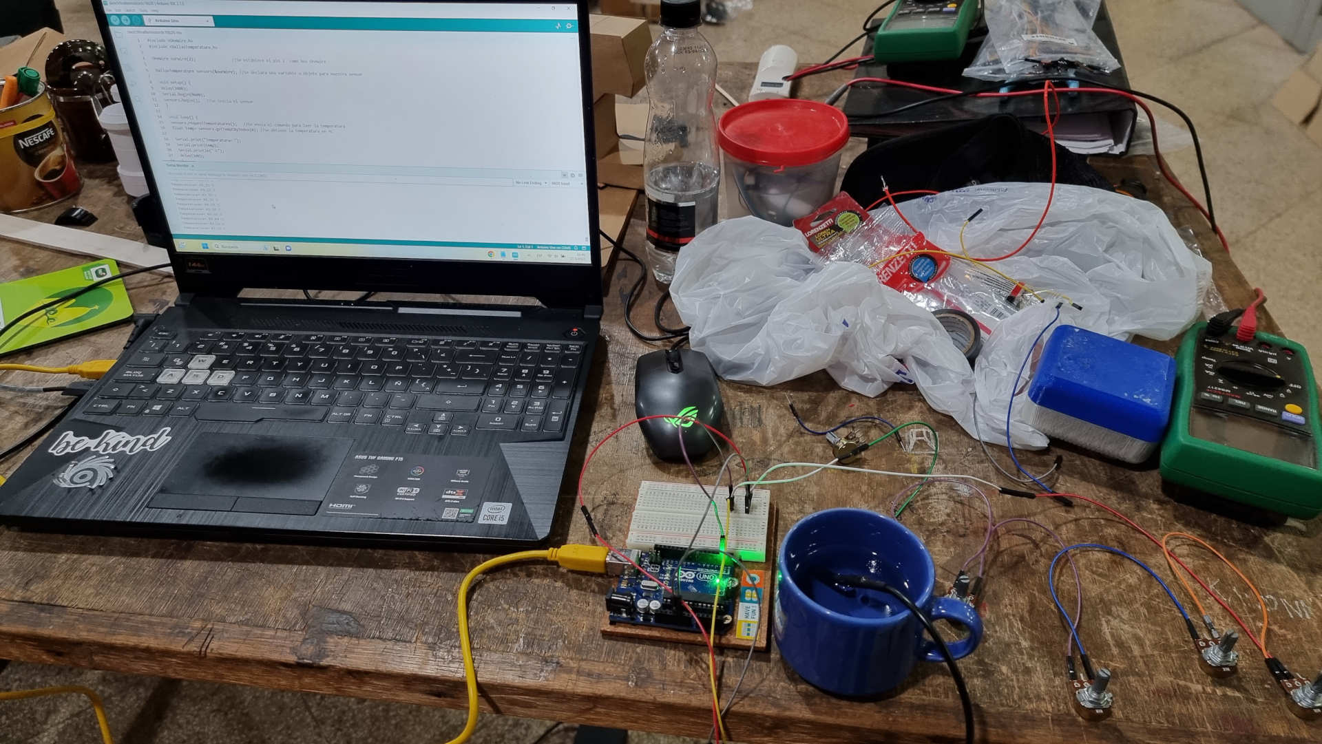
First, i test it with some help of 5 potentiometers....why? Because it was late and couldn't find a 4.7k...and it worked great.
I also follow thisTutorial, which was very useful.

With these test and the results, i decided to made a board, one width the same insights
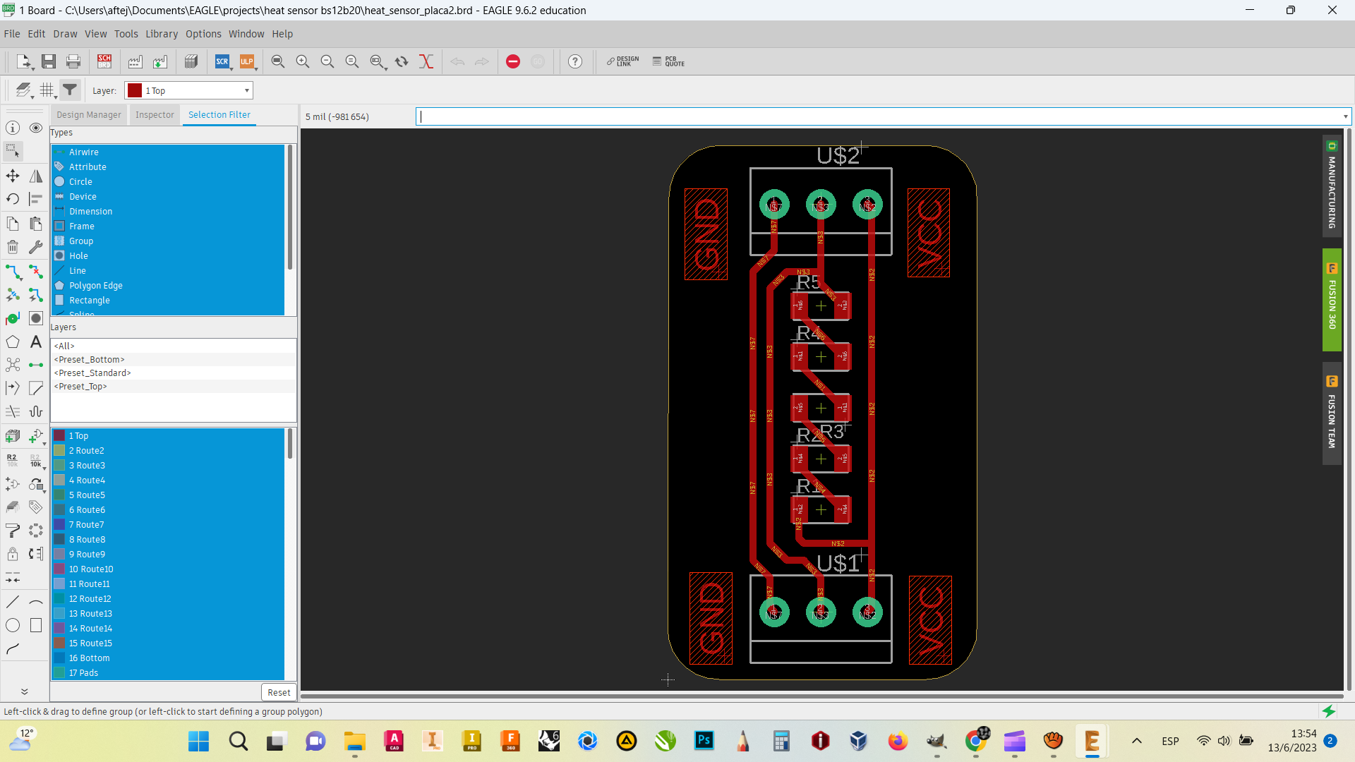
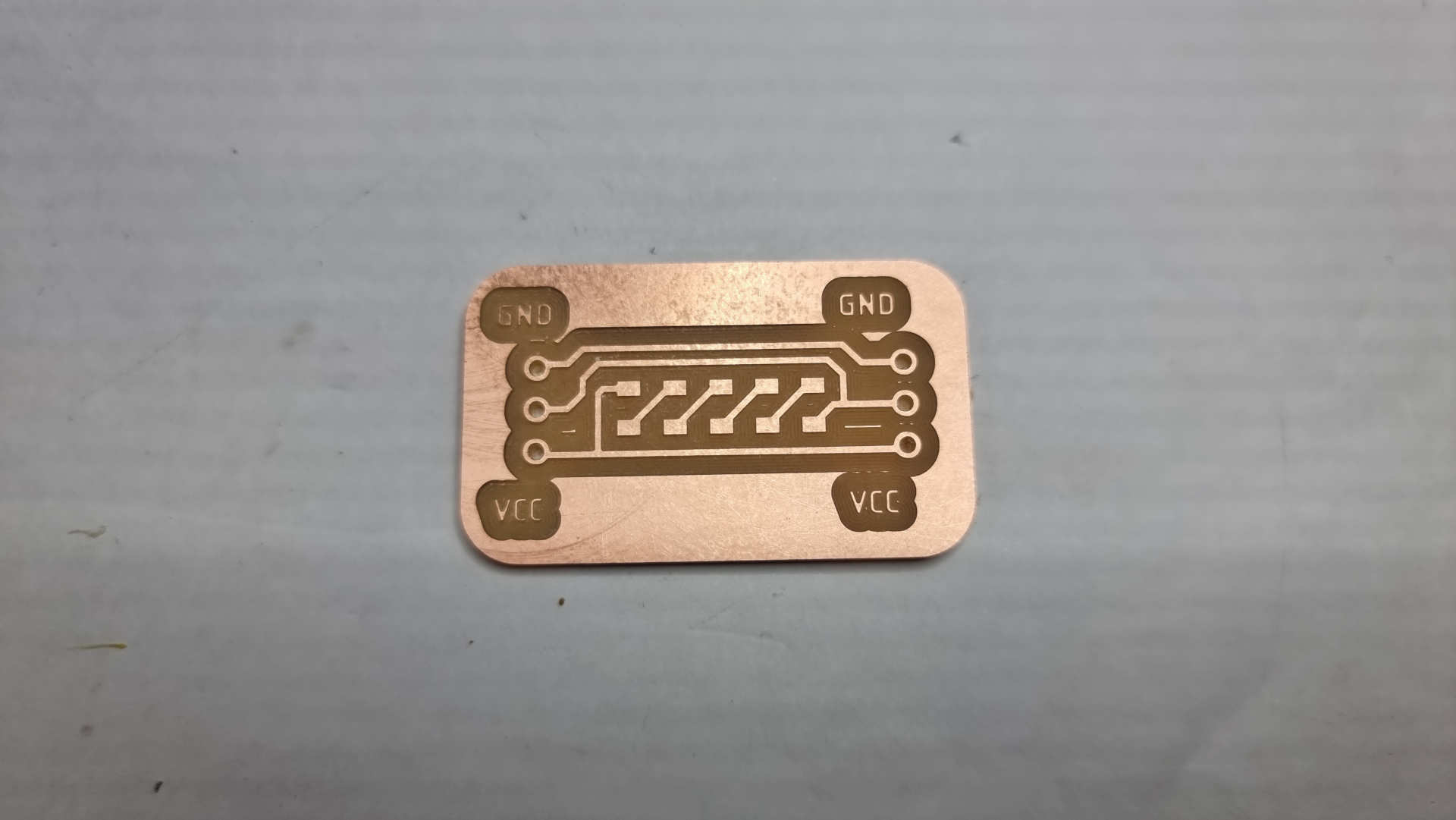
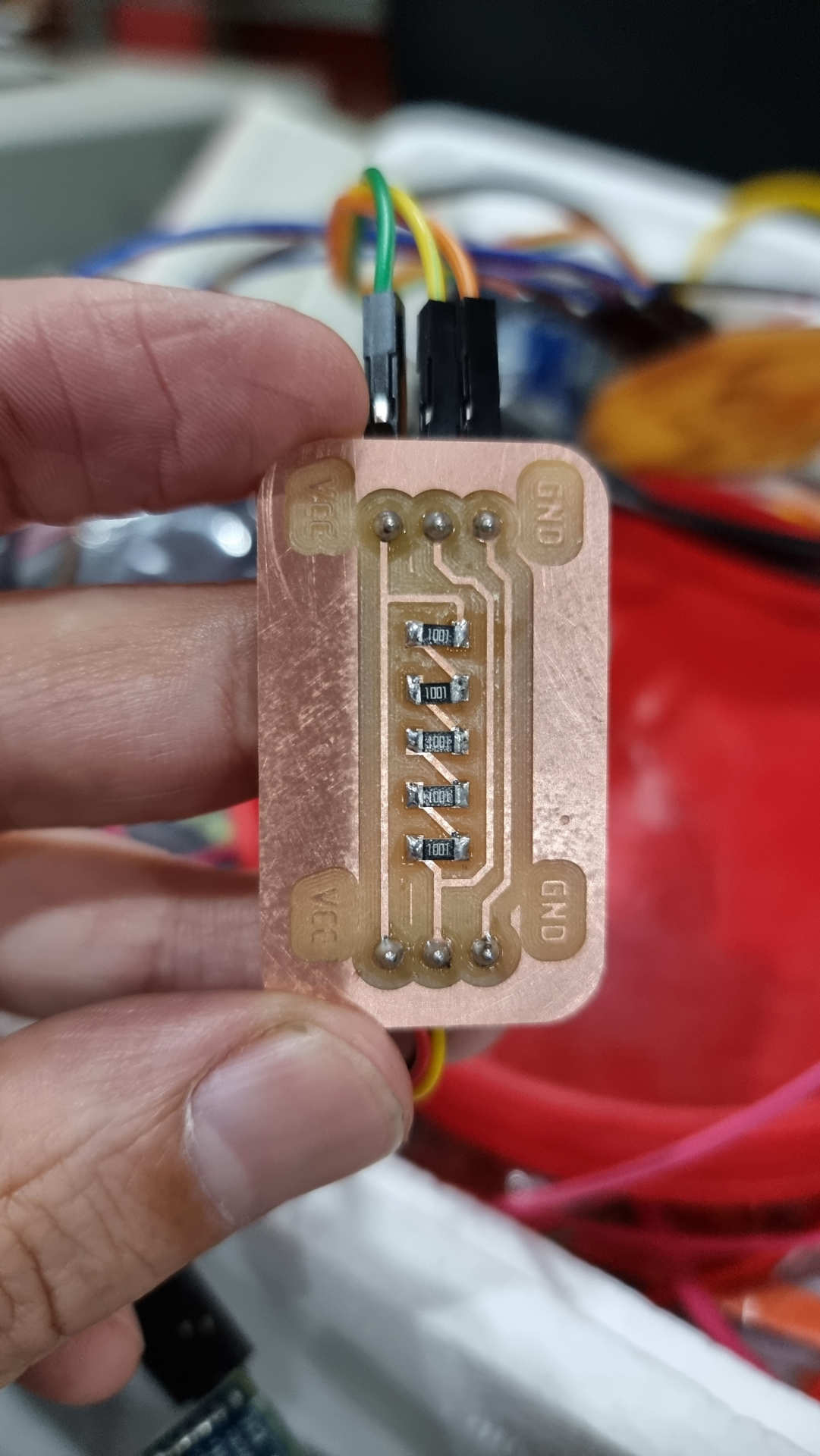
After having all the readings from this module, i decided to make a more reasonable board, width a 4.99k ohm.
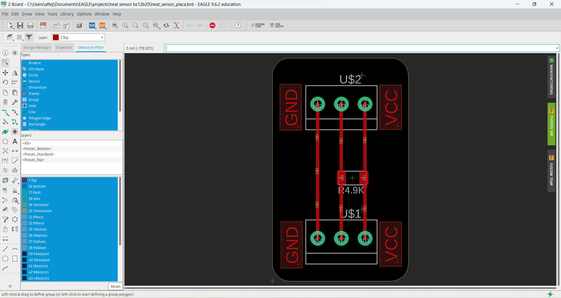 Heat sensor module