6. Electronics design
Electronics...basic knowledge
6th week past by.....electronic design....what is it?
Well, basically, we learn how to transform a sketch of a circuit into a work of art circuit board....from plain schematicts to a machinable PCB.
Even functional....not only for show.
What we need to know to start making....first, what´s a circuit?
Circuit
Electronic circuit is a kind of circuit comprising of electronic components such as capacitor, resistor, diode, transistor, inductor, coil, transformer ,etc. These components can be either through-hole or SMD..
The arrange and the value of the components give properties to the circuit that can give different uses.
Those components can be connected parallel or in series.
The schematicts
From a sketch of an example circuit we start to work.
We learn about components....symbols and how they work.
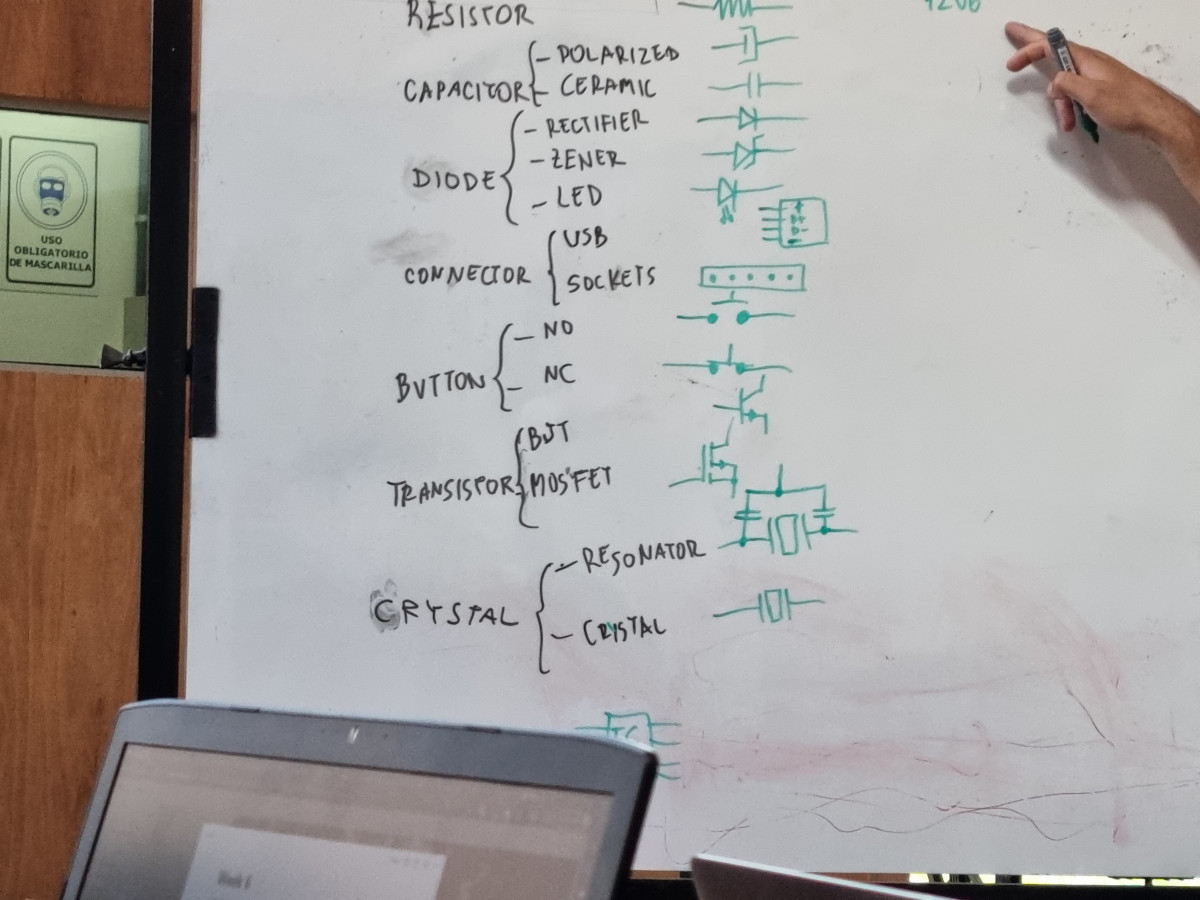
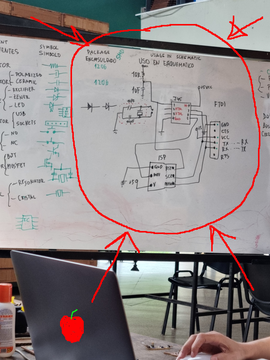
Ok, now we now what is a circuit, what are the parts that we need to use.....so, let´s design it.
Eaglefrom autodesk was the chosen software to design the future board.
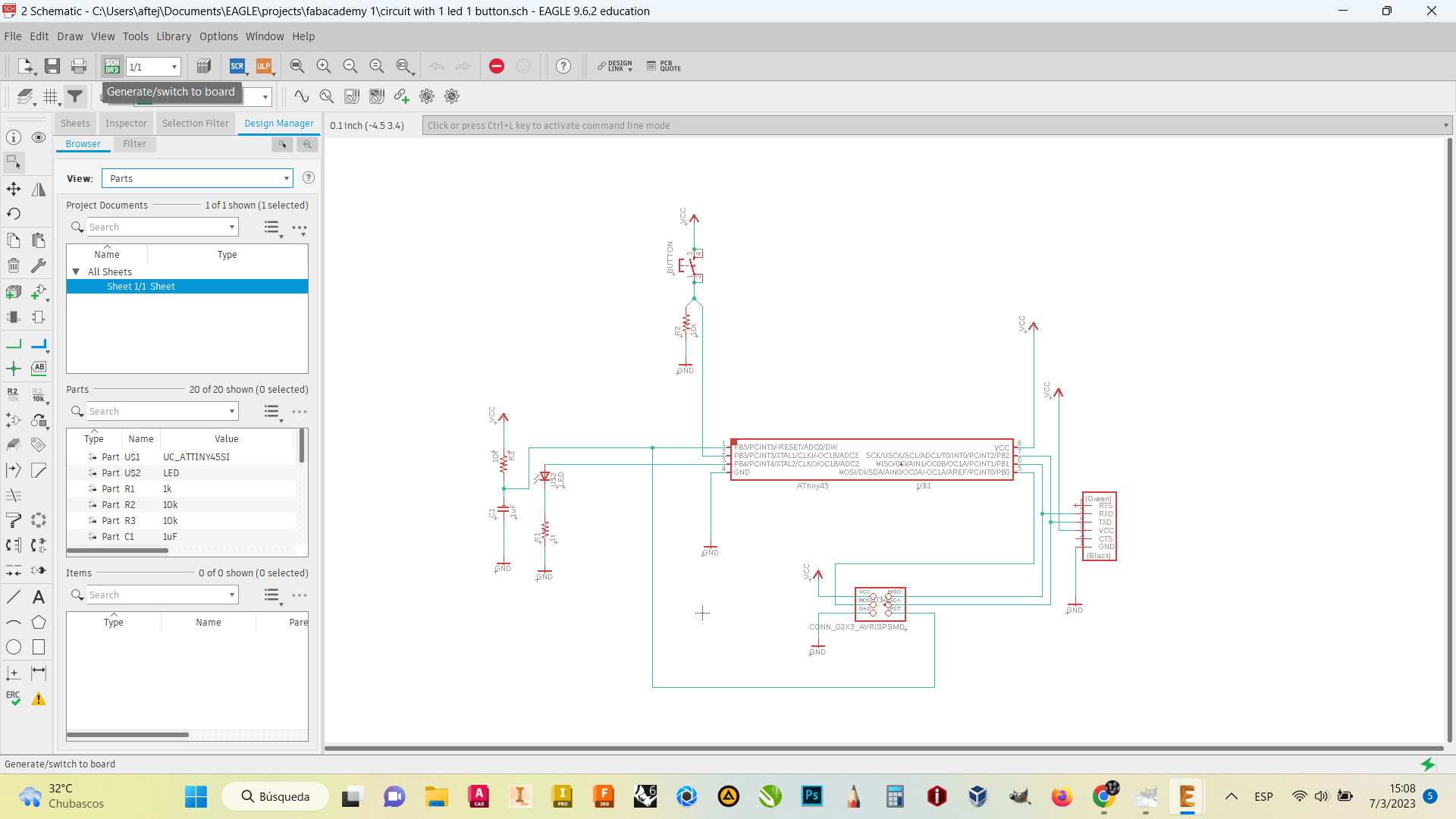
You need to start a project in Eagle, and create a new schematic.
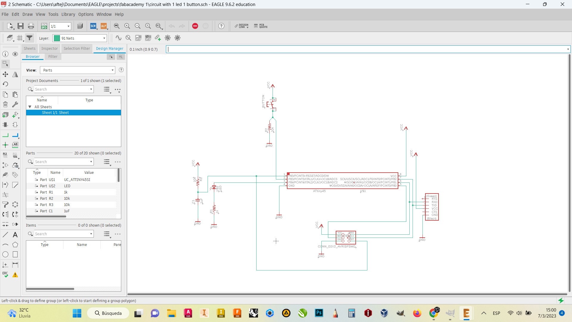
In the schematicts you need to add every component that you might need to make it work.
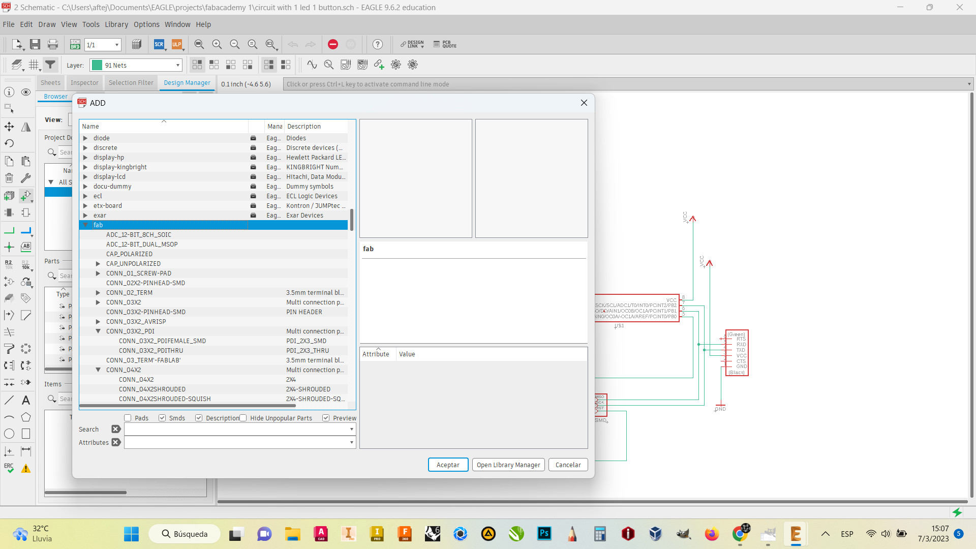
If your desired component is not in Eagle library, you need to import it from manufacturers libraries or from the FabAcademy Git files.
Once you have all, you need to connect them correctly...in case you want them to work.
So, you have your schematics with no DRC errors.....export it to make a board.
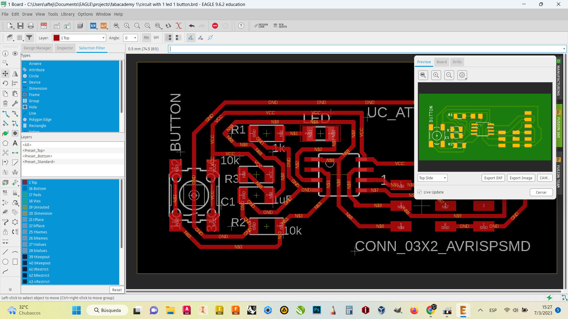
That´s all....not even close.....you need to arrange your parts to make path with no electric/signal interruption.
following the Design rules, giving the paths the width and the clearence to avoid generating short circuits.

We have our board ready to be manufactured....we get the Gerber files, the parts list and even we export to Fusion360 and get a 3D model.
By the way.....why don´t we make a case....let´s do it.
That´s all folks....to be continued.
Circuit board Link to group assignment