Final Project
Modular Machine Building
Slide

Presentation
License
This project to be licensed under the general Fab Academy license

Project Process
Inspiration/Ideas
-
I really enjoyed working on our “fab Buffer” group project for machine week and have decided to change my final project to improving our machine. Part of the motivation for changing to this project is that I’d like to use it as a springboard to develop a high school engineering curriculum on machine design.
-
Here are some of my ideas for the improved machine:
- Simplify the assembly of the design by improving the fit of some basic components with some spring loading of the wheels on the extrusion.
- Accurately model the machine in Fusion 360 with a mechanical design study.
- Use off the shelf components for the base design.
- Make custom electronic board components to match with the Creality stepper motors
- Add electronic z-axis control (stretch) using LIDAR to move the bed to the correct height.
- Integrate gyroscope sensor to smooth our the CoreXY motion with a feedback look for acceleration and deceleration.
- Use solely USB-C power for the machine.
- Design for ease of assembly.
- Use the Modular-Things interface
Bill of Materials
PCB Bill Of Material
3D Design/Modeling
-
I will be using Fusion 360 to model the design for my final project. First I must move the file from our machine week group page to my personal account. I think the best way to do this is to download the model and the upload if to my Final Project folder in Fusion. The machine week model is in an account with Basic Access and cannot be downloaded, so I will remake the Fusion Model. This will allow me to work on my Fusion360 skills.
-
Current Model
-
Issue-When copying and pasting the extrusion components in Fusion 360, the copied component and the original were linked and modified together. For example, when modifying the length of the extrusion it was copied from would change in sync.
-
An online search found the solution. It is not currently possible to break the link between copy and pasted components unless the timeline is deactivated. Once that is completed, right-click on the copy and “Make Independent”
-
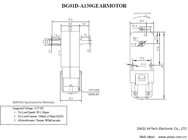
Once that was resolved I was able to recreate the 3D model more efficiently. However, I still needed to redesign the toolholder on the gantry for the DC motor. As I mentioned in my Interface week, with the goal of using USB-PD power for the project, I need to switch from the drone motor with the ESC and external power supply to a 5V DC motor that I could get to run with XIAO. After some research, I chose the DAGU DG01D 48:1 DC Gearbox based on the 4.5V suggested voltage on the datasheet. Also, we had some in the lab inventory, so it was a convenient choice also.
-
Initially, I was designing a toolholder that could be attached to some sort of z-axis that was still theoretical, so it was just a simple rectangular box with a cutout for the motor. I went online and found a 3D model of the DAGU DG01D that I used to created the toolholder in a way similar to how I make the feet for the molding and casting, except in reverse. After that I went through an iterative process of design, print, and adjust to get to the final design that would allow for motor to slide into the toolholder and stay in place with the buffing tool attached.
Iterations of the design to get a snug fit. 
-
Here is final design:
-
Buffing tool design to fit snugly on the gear of the motor:
-
At a certain point I decided against the idea of adding the z-axis due to time and space constraints, so I integrated the toolholder with the gantry plate here:
3D Printing
-
The majority of the 3D printed parts for this project come from a combination the UrumbotXY and Beehive -axes machines that are in the Fab library for Machine Building.
-
Here is the 3D printed toolholder I designed.
- With organic supports

-
With supports removed

-
Here is the before and after photo of the redesign with the new DAGU DG01D DC motor versus the old drone motor.

2D Design and Laser Cutting
-
The acrylic platform for the machine was cut using our Epilog Fusion Pro 48 laser cutter.
-
Here is the design in CorelDraw. You may notice that the Charlotte Latin Fab Lab logo is reversed and that is on purpose, so the logo is on the underside of the platform and has a cleaner look.

-
Finally, here is the finished lasercut acrylic base.

Electronics Design and Production
Fab23 XIAO Dual H-Bridge
-
To start, I’m going to make and understand the Xiao_RP2040 Dual H-Bridge board from the Instructor Boot camp 2023 to see if I can understand how it works, so I can then adapt it to my project.
-
I ran into some issues with downloading the existing board to be milled. We don’t use Mods in our lab, so I needed the BRD file to use in Eagle or KiCad. When I clicked on the link the file didn’t download the BRD or SCH files like I’m used to. Here is what came up instead.
- This XML file does not appear to have any style information associated with it. The document tree is shown below.

-
I went back and tried to right-click on the file to see if the “Save File As” option appeared and no luck. Here is what I got. “Save link as” which seemed like bookmarking the site which was still no use.
-

-
I did some internet searching for importing XML files into Eagle or KiCAD and came up empty, so I tired to copy the text in to a Notepad file and change the extension from “.TXT” to “.BRD” and no luck. I kept getting import errors.
-
At this point it seemed like I would have to recreate the board in KiCad using the PNG file as a template, but I was reluctant to do all that work as from a process perspective I didn’t feel I had exhausted all my options. However, the clock is ticking. It presented me with one of the typical Fab dilemmas use the brute force approach and recreate the wheel since our tools are similar but not the same to just get it done or keep searching for a simpler solution. When I showed other people the issue it was something they had not encountered, so I was really stuck.
-
I decided to wait until the next morning ask in Global Open time to see what I might be doing wrong. When I brought it up in Global Open Time, Adrian and Rico were initially confused, so I was able to share my screen on the Zoom call. Adrian navigated to the same page and right-clicked and got same spot, but his was in Spanish, he indicated that all I need to do was click on the fourth item down, and it would work. I tired it and it did. Easily solved and frustrating at the same time. Typically, in Chrome right-clicking on a file link bring up the option to “Save file as” and it’s no issue, but “Save link as” typically (until this instance) only allows you to save a link.
-
As frustrating as this was I’m glad I didn’t give up and recreate the file because it’s happened before when I’ve been browsing files on the Fab site to mill as a starting point. By realizing this quirk in the system, I just widened my options for starting points for designs. Worth the effort.
-
Some time has passed (almost a year) and I’m coming back to this project. I’m looking at the motor driver board for this project and it seems like there is an updated motor driver for Clank that may work. I found the Building Clank site and opened the Fusion 360 file and took a look. The board was part of Modular Things. When I went to the site and looked and found it to be stepper-hbridge-xiao
-
I’m reviewing the motor drivers I was going to use for this project to see if any updates have been made to the Xiao_RP2040 Dual H-Bridge board I was planning to use.
-
It looks like updates were made during FAB23 Machine Workshop to the whole base design I started with, so I will start updating my design with it.
-
The first item I’m going to concentrate on is the Xiao RP2040 HBridge Board2. I downloaded the file and took a look at it in KiCad 8. It seems pretty straightforward to mill.
-
While it seemed straight forward to mill, I’m having issues getting the ground traces to mill on our OtherMill Pro and Bantam Desktop CNC. When I loaded the gerber files into the Bantam Software the milled file does not match the gerber. See the two screenshots below.
-
While I was figuring out this milling issue with the Bantam Mill, I went ahead an ordered some boards board from JLCPCB to get started and also make sure that I had a good board to start with when soldering to help troubleshooting. After contacting Bantam Tools about the issue, I learned that I needed to change a software setting to correct the issue. I needed to select “Use Details Tool Everywhere” to mill the board, so I will go ahead and use the JLCPCB Board I ordered first to get the machine working and will step back and use a milled board after I get it working to demonstrate the skill.
-
After the JLCPCB Boards arrived, I stuffed one. As I stuffed the board, I continually used my Kaiweets HT118A multimeter to confirm the components and continuity. Hopefully, I have a good board to use when it’s all done. Here is a photo of the stuffed board.

-
I had the board stuffed and wanted to see if I could get it to work. I uploaded the uf2 file from the Fab23 machine workshop to the board. After that I went to the Modular-Things website in Google Chrome to see if I could get it to work. It was a mixed bag. I was able to get the site to see the stepper board, but was unable to get any movement. I discussed the solution to this issue in the Interface and Application week in the Code section here
-
As for the milled version of this board, the successful completion of that task is also in the Interface and Applications week in the Board Production section here


DC Motor Control Board
-
As I mentioned above in 3D Modeling #4, for a variety of reasons, I switched from the drone motor to the DAGU DG01D DC Motor. My idea was that being a regular DC motor, I could use the Toshiba motor driver that I already was using for the dual h-bridge and run the DC motor with just the XIAO RP2040 and not need an external power source like I did for Output Devices week.

-
To test my theory, I stuffed on the JLCPCB Dual H-bridge boards, with only one motor drive and tested it out. Here is the schematic for the setup.

-
Here is the test setup using a basic PWM DC motor code with the help of ChatGPT:

-
Once the test was successful, I used KiCad 8.0 to design a new DC motor control board using FAB23 Machine Workshop Board2 as the starting point.
-
Here is the final design for the board in KiCad:

-
Here is the milled board before stuffing:

-
After stuffing, troubleshooting and preparing for testing.

-
Final Milled DC Motor Board Test-Success
Coding
-
I’m using the Modular-Things website for control of this machine to aid in teaching students the parts of the machine and how to control it.
-
The coding for this part of the project was produced as part of Interface and Applications week. Link
Molding and Casting
- The feet for this machine were produced as part of Molding and Casting week Link
CNC
-
I used the ShopBot to put some pocket holes in the wooden base for my project that project feet could sit in to aid in stability.
-
Here is the design of the four 1.6” diamter pocket holes in Aspire:
-
2D Design

-
Toolpath setup with 3/8” Compression Bit
- Zeroing off the machine bed with a pocket depth of 0.2”


-
The cut
-
Finished base
-
Machine with feet installed in base


Final Assembly
At this point I had everything working while connected to my Windows PC, so I needed to move everything over to the 7” touchscreen and Raspberry Pi 4 machine to finish up the project.
Assembling the 7” Touchscreen and Raspberry Pi:
- Here is a link to the documentation I followed to assemble the touchscreen and Raspberry Pi


Imaging the Raspberry Pi
- Here is a link to the documentation to image the Raspberry Pi


Connecting the machine to the Raspberry Pi and testing
- Sabrent USB 3.0 7-Port Hub+3 Smart Charging Ports With Powered Switches connects to the wall and the USB 3.0 port (the blue one) on the Raspberry Pi

- Intial Setup

- Adding the keyboard and plugging in the USB-Cables to the Sabrent USB 3.0 7-Port Hub+3 Smart Charging Ports With Powered Switches

- The part that isn’t shown in the pictures is that once everything was connected I had to open Chromium on the Raspberry Pi and log in to my Google account to retrieve the Modular-Things code to test. I had the final code in a Google Doc and it was a straightforward copy and paste into the Modular Things website to get started.
- Once that was completed I powered on the ports on the USB hub and paired the Dual H-Bridge boards to the Modular-Things site like I did for Interface and Application programming.
- As it’s not controlled by Modular Things, I also powered on the DC motor control via the button on the USB hub to get it spinning.
- I ran the “Draw Square” routine with the DC motor spinning and filmed the results below.
- It worked, and I considered the project complete for now.
Link to files
Link to my all project files.
Acknowledgements
- This inspiration for this project came from our machine week project and the ModularThings project.