14. Networking
View our group documentation on getting my, and Dan Stone's projects communicating through I2C.
| Design File Links |
|
|---|---|
|
-
Attiny1614 and 412 Haptic Touch Tester
- I2C Test Code |

|
Designing ATTiny1614 Input with ATTiny412 Haptic Controller
|
For the full breakdown of the design process for this board, you can check out
my documentation for Input Devices week.
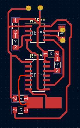
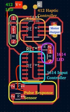
To summarize, this board is designed to test the concept of using a step-response sensor powered/measured by the 1614, and a haptic actuator controlled by the 412.
The two large pads on the bottom act as the step-response input. Both microcontrollers are connected to an LED for debugging, and the 1614 and 412 are connected together via their SDA and SCL pins.
My ultimate goal with this is to use the 1614 to have multiple step-response sensors attached as buttons, and then communicates with my main project via I2C to tell it what button has been pressed. The 412 controls 4 haptic actuators to give tactile feedback to the user when they press the step-response buttons, to emulate button clicks. |

|
Code for I2C Peripheral -- 412 Haptic Motor Controller base
|
I designed this code to be open-ended. The idea is that you can expand upon this code to develop whatever you want.
It receives a character and does an action based on such.
I referenced the
Wire Arduino library
to build this I2C functionality.
This code is for any peripheral device, and you can see the controller code that it works with in the section below.
It sets the address for the peripheral to 25, although any number between 8 and 127 should work. Some I2C devices require the 0-7 bits for setup or configuration purposes, so I avoided these numbers altogether. In fact, 120 devices is probably overkill for most use cases, so as long as you don't have two devices with conflicting addresses, you shouldn't run into any "collision" events where the controller tries to talk to two peripherals with the same address. Collisions will cause improper functionality, since the receivers and sender rely on "awknowledge" and "request" messages when talking to one another. Think like multiple people trying to talk over eachother -- it just becomes a garbled mess. How this code works is it basically waits to receive a message before deciding what to do. It is important to put any delays and main functionality in the loop() function, since it will call the readMessage() function as an interrupt when receiving a message from the controller. If this interupt contains "expensive" code, meaning resource/time exhaustive, then the interrupt will interrupt itself, failing to complete the whole function since it constantly calls itself midway through. So instead, I kept the interrupt simple - all it does is read the byte and decide what to do from there. If I were to receive messages that were more bytes, this parsing of data would need to be moved into the loop() function to avoid interrupted interrupts. So, the readMessage() function will let us know if an 'f' or 'h' is received from the main controller, and in the main loop we decide what to do with that information. In this case, I set it to blink the LED once if 'h' is received, and twice if 'f' is received. |
#define LEDPIN 1

// where the controller should send the message to this device
// -- can be anywhere from 8 - 127
#define I2CADDRESS 25 // what's funnier than 24?

#include "Wire.h"

// tells us if this 412 received an 'h' or an 'f' from the controller via I2C
bool hReceived = false;
bool fReceived = false;

void setup() {
  pinMode(LEDPIN, OUTPUT);
  Wire.begin(I2CADDRESS); // enable as peripheral at I2CADDRESS -- 0x25
  Wire.onReceive(readMessage); // function called when a message over I2C is received
  digitalWrite(LEDPIN,LOW); // ensure LED is off at start
}

// read the message, and decode whether or not an 'f' or 'h' is received
void readMessage(int bytes){
  if(Wire.available()) { // go through each character in the message
    //-- for this test case there should only be 1 char
    char c = Wire.read(); // read received byte
    if(c=='h') hReceived = true; // received 'h'
    if(c=='f') fReceived = true; // received 'f'
  }
}

// main loop
void loop() {
  // 'h' is received from controller
  if(hReceived){
    // blink LED once
    digitalWrite(LEDPIN, HIGH);
    delay(100);
    digitalWrite(LEDPIN, LOW);
    hReceived = false;
  }

  // 'f' is received from controller
  if(fReceived){
    // blink LED twice
    digitalWrite(LEDPIN, HIGH);
    delay(100);
    digitalWrite(LEDPIN, LOW);
    delay(100);
    digitalWrite(LEDPIN, HIGH);
    delay(100);
    digitalWrite(LEDPIN, LOW);
    fReceived = false;
  }

  delay(100);
  digitalWrite(LEDPIN, LOW); // make sure the LED is off when a message is not received
}
|
||
How I Verified the I2C Connection |
|||
|---|---|---|---|
|
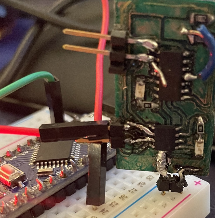
If you have written code for your I2C device (or turned an I2C enabled chip on), you can test whether or not it is on the I2C SDA and SCL lines by using a scanner.
This I2C scanning test code will tell you what devices are connected to the I2C bus.
Just run this on a RP2040, hook up the SDA and SCL, and you should be good to start debugging from there!
Source Code This test should work for any I2C enabled device, but specifically in the context of this project, it works for both the 412 and the 1614. When using the 1614, just make sure you connect it to the proper SCL and SDA pins, since the pinout of the 412 and 1614 are not the same. |

# https://gist.github.com/projetsdiy/f4330be62589ab9b3da1a4eacc6b6b1c
import machine
# define I2C port 1 with SDA on pin 7 and SCL on pin 6
i2c = machine.I2C(1, scl=machine.Pin(7), sda=machine.Pin(6))
# scan for I2C devices
devices = i2c.scan()
# print the list of devices found
for device in devices:
    print("Decimal address: ",device," | Hexa address: ",hex(device))
|
Code for I2C Controller -- 1614 Step-Response Sensor Base

|
#define sensorPin 2
#define pulsePin 5
#define ledPin 9
#define nSamples 64
#define SDAPIN 6
#define SCLPIN 7
#define MOTORCONTROLLER 25
#include "Wire.h"
void setup() {
PORTB.PIN1CTRL |= PORT_PULLUPEN_bm; // enable pull-up resistor for SDA
PORTB.PIN0CTRL |= PORT_PULLUPEN_bm; // enable pull-up resistor for SCL
pinMode(ledPin, OUTPUT);
pinMode(pulsePin, OUTPUT);
pinMode(sensorPin, INPUT);
Wire.begin(); // Begin as controller, not peripheral
blinkLED();
}
double readPulse(){
//digitalWrite(pulsePin, HIGH);
delay(1);
digitalWrite(pulsePin, LOW);
char readings[nSamples];
for(int i =0; i
|
