12. Input Devices
For this weeks topic, the idea of creating step-response touch buttons really captivated my attention, just mainly due to the simplicity and ingenious behind the implementation and theory behind it. step-response sensors rely on measuring the change in the electromagnetic field between 2 capacitive plates. It is interesting because it applies a very simple approach to detecting changes in a variety of manner, such as distance, material, motion, and touch. I think it would be interesting to use these as the methodology for physically interfacing with my final project, since it seems like a fun idea, would be pretty power efficient, and could be combined with haptic actuators to give a variety of use feedbacks. This could include a single click (haptic motor vibration) for pressing the "play" button, or 2 clicks for pressing "pause". Having the option to provide multiple methods of feedback to the user via touch allows for a more accessible product, and also allows for a more intuitive user experience.
View our group work for this week here: Analyzing and Using the Adafruit BMP280 I2C or SPI Barometric Pressure & Altitude Sensor
|
|
||||

Designing Step-Response Sensor PCB Gerbers
| I want to incorporate the step response sensors into my final design, but I first need a basic circuit to test how it works, and as a basis for the implementation. I have designed this board with the goal in mind of basically taking the schematic and throwing it into my main project, after verifying the idea works. | |
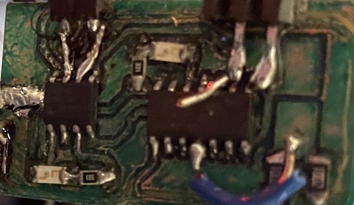
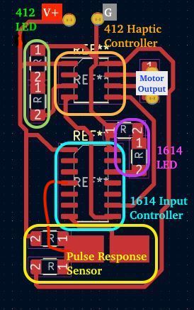
This board consists of a few main components and systems that it manages.
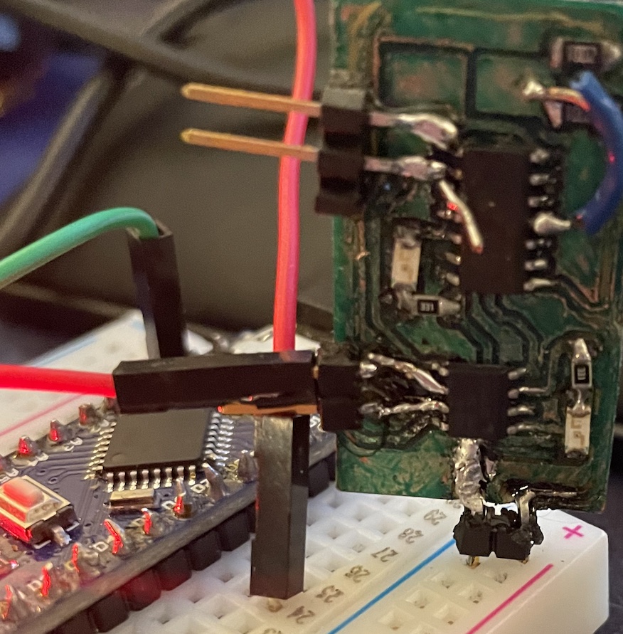
The 1614 and the 412 are connected via the SDA and SCL lines, and share a common ground and V+ supply. The 1614 will send steps and read information from the step sensor, then send a message via I2C to the 412 to tell it to make the haptic motor. For testing purposes, I have implemented it using LEDs instead of the motor, to verify that the boards can communicate first before moving onto the motors. |
|
| The 1614 Input Controller | |
|---|---|
|
For the scope of this week, I will be talking mainly about the 1614, and how it sends a step and reads it, then decides what to do with it.
In networking week, I will go into further depth on the implementation of I2C, and communication between the 1614 and 412.
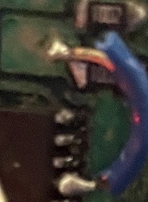
Note that I had originally forgotten to include the trace with this tester that connects the step-sensor to the 1614.
I redrew the schematic pictures with this trace included, but you will see on my final result that I used a piece of wire to create this connection.
Since the purpose of this board is for testing the setup, I didn't see a reason to mill a new board with the fixed trace included, but I have fixed the gerber file in case you wanted to try out this circuit yourself. |
|
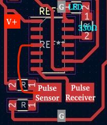
Step-Response Sensor Design |
|
|
|
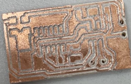
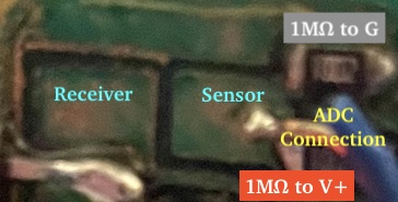
| The design of the step-response sensor is based on how Neil described a simple setup for creating them during the lecture. It consists of 2 plates. One receives the step, and the other is impacted by the step from the former. We need to set a DC voltage bias to the sensor side, so I attached two 1M ohm resistors to it. One pulls it up to the voltage supply, and the other pulls it down to ground. This biases the sensor's middle reading to half of the input voltage, allowing us to read positive and negative changes in values. The receiver plate will be pulled up by the 1614 supplying a positive potential from an output pin. This causes charge to build up on the sensor plate, which can then be read using the built-in ADC of the 1614. |
|
| For the 1614, the code consists of a few key components including the step-control, the step-sampling, I2C messaging, and the LED output. The LED's purpose changes throughout the testing, but typically it just blinks on and off depending on what it reads from the sensor. | |||
Basic Sensor CodeThis code is what I used to first test the sensor. How it works is it basically sends a pulse to the receiver pad, and then I measure the voltage on the sensor pad immediately during, and immediately following the pulse. I then store the difference between the two values into an array, and repeated until I had 64 samples of these differences. Then, depending on the average of the 64 samples, I sent a command to blink the LED if this change reached a certain threshold. Now, keep in mind, this was my first attempt at making this step-response code, and it has a fundamental flaw in how it works. Instead, it acts more like a capacitive touch sensor, which is fine for the testing applications for this week and the networking week. You see, I was measuring what we would call the instantaneous rate of change at one moment, but with a step-sensor, we want to be measuring multiple cases of instantaneous rate change and returning the average of them. Here is a video showing how it lights up when the touch sensor is "pressed". |
#define sensorPin 2
#define pulsePin 5
#define ledPin 9
#define nSamples 64
void setup() {
// put your setup code here, to run once:
pinMode(ledPin, OUTPUT);
pinMode(pulsePin, OUTPUT);
pinMode(sensorPin, INPUT);
digitalWrite(ledPin, HIGH);
}
double readPulse(){
digitalWrite(pulsePin, HIGH);
delay(1);
digitalWrite(pulsePin, LOW);
char readings[nSamples];
for(int i =0; i
|
||
Fixed Step-Response CodeThe above code really only works as a capacitive touch sensor, since the way it measures the change in response is based off one pulse, instead of multiple. Using this code linked on the Fabacademy page by Neil, I realized what my mistake was and rewrote readPulse() function on the right.This readPulse() function takes into account the instantaneous rate of change over multiple intervals and averaging them, resulting in a more accurate and sensitive reading.
|
double readPulse(){
digitalWrite(pulsePin, LOW);
char readingHigh = 0;
char readingLow = 0;
char readings[nSamples];
// collecting readings
for(int i =0; i
|
||
Haptic Motor Setup | |||
|---|---|---|---|
| My initial idea used ERM (eccentric rotating mass) vibration motors to produce the haptic feedback touch response. These motors spin with a counterweight to create vibrations. Since they are dc motors, they just need a voltage applied across its terminals, and the direction can be reversed by reversing the polarity. I had this initial design for a way to control the direction and on/off states to control each motor using 2 pins from the microcontroller. This design took a lot of iterations, and is a little complex for such a simple application. | |||
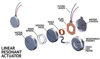
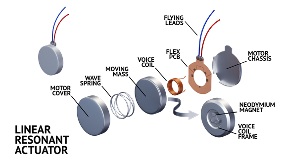
| After researching methods of haptic feedback, I stumbled upon LRAs (linear resonant actuators) which essentially use a coil and a magnet to vibrate by creating opposing magnetic fields. By setting a voltage across its terminals, the inductor inside the LRA will create a magnetic field according to the direction using the right hand rule. This will cause the magnet in the center to be forced to one side of the LRA, and when the charge is reversed on the inductor, the magnet will go to the opposite side. The moving of this magnet due to changing the direction of current causes vibrations in a linear motion. This also has the benefit of working at a lower voltage and with less current. The vibration component also feels different, since it is a linear movement rather than rotational like with the ERM motor. Hopefully, this will give a more tactile "click" feel as opposed to a "buzz" or vibrating feel. |
Source |
||
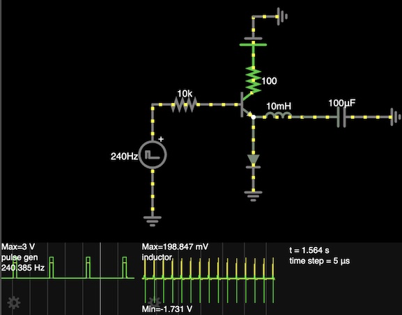
| Due to the lower requirements in terms of energy and voltage to run the LRA, the circuit design ends up being very simple. The vibration of the LRA is due to the changing direction and force of the magnetized weight, so using a pulse signal should be fine to just "throw" the weight to each side. In the circuit on the right, I have added a capacitor in series with the LRA (represented by the inductor) to cause brief oscillations. This will cause the LRA to do one full cycle in both directions. It works similarly to a debounce by charging with the input signal, then discharging when the input signal is released. This circuit setup is nice since it uses only 1 pin for the input, and utilizes the capacitor to reverse the current direction, meaning less wasted power and only removing the requirement of 2 switching transistors to power up the two directions. |
|
||