Group Assignement: Computer controlled machining
Versatil 2500 SB Milling Cutter
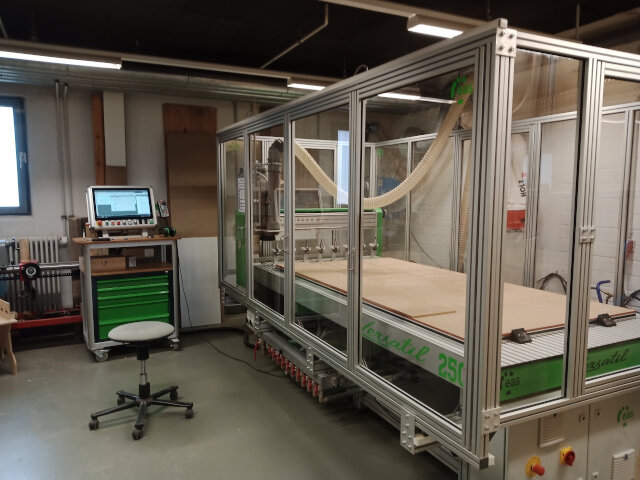
We are utilizing the Versatil 2500 SB milling cutter, which is equipped with a full enclosure. This safety feature prevents the milling process from starting until the enclosure is closed, thus providing protection against injuries from potential debris. Additionally, access to the milling area is only possible when the machine is powered off, ensuring safe operation. Ear protection is required while the CNC is active due to high noise levels.
Mounting of Plates
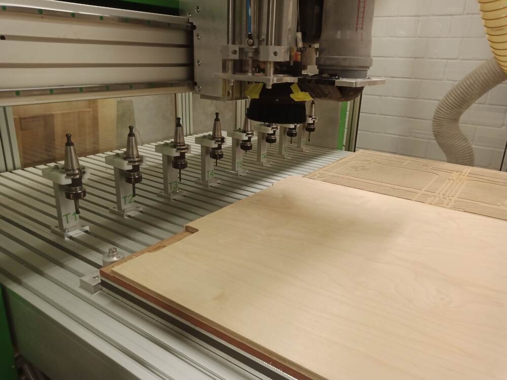
For securing plates, we use a vacuum table that firmly holds the workpiece even through MDF sacrificial plates. Smaller plates are additionally fixed with wood screws on the sacrificial plate. The milling cutter also includes an automatic tool changer with a capacity for 10 tools, which can be selected directly in Fusion 360 using predefined parameters for precision. To ensure safety, it is recommended not to modify these milling parameters.
Technical Data of Versatil 2500 SB
- Travelling Distance: 2500mm x 1250mm (+1000mm swivel arm) x 170mm
- Space Requirement: 3000mm x 1650mm (+1000mm swivel arm) x 1600mm
- Worktable Height: 950mm
- Passage Height Portal: 260mm
- Weight: Approx. 550kg
- Drive: Hardened ball screw with 10mm pitch and self-adjusting nut to minimize backlash
- Linear Axes: Two ground rails and recirculating ball slides per axis
- Stepper Motors: 230 V, 4A, 900Ncm for X, Y, and Z axes
- Accuracy: Max. positioning error 0.1mm; Technical resolution 0.00625mm; Repeat accuracy +/- 0.025mm
- Speed: Positioning speed of 24,000mm/min
Speed and Feed Calculations
To verify the accuracy of the speeds and feeds, I recalculated these parameters using the formulas and values found in Sorotec's Guide.
Speed Calculation
Formula: n [rpm] = (vc [m/min] × 1000) / (3.14 × Ø d1 [mm])
- Variables:
- n = Speed of the milling cutter in rpm
- vc = Cutting speed in m/min (for hard wood: 450 m/min)
- d = Cutter diameter in mm
- z = Number of teeth (in our case: 2)
- fz = Tooth feed
- vf = Feed rate in mm/min
- For a 6mm cutter diameter:
450 x 1000 / 3.14 x 6 = 23,885 rpm; Fusion 360 setting: 22,000 rpm, which is within range. - For an 8mm cutter diameter:
450 x 1000 / 3.14 x 8 = 17,914 rpm; Fusion 360 setting: 20,000 rpm, slightly higher but acceptable.
Feed Rate Calculation
Formula: vf = n × z × fz
- For a 6mm cutter:
22000 x 2 x 0.055 = 2,420 mm/min; Fusion 360 setting: 3100 mm/min (higher, possibly calculated for softer wood). - For an 8mm cutter:
20000 x 2 x 0.065 = 2,600 mm/min; Fusion 360 setting: 3500 mm/min (higher, possibly calculated for softer wood).
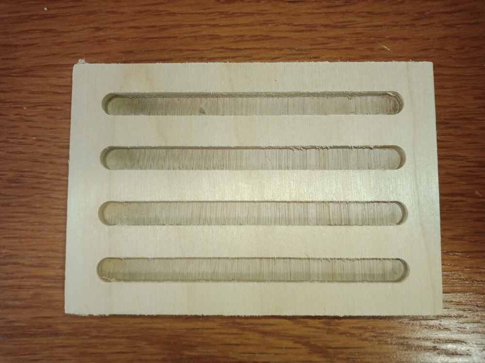
Testing with the 8mm mill showed consistent cut quality across various feed rates (3500, 3000, 2500, and 2000 mm/min). Using the highest speed offers the advantage of faster milling without compromising precision. The cut width (kerf) for all cuts is 8mm.
Below is a video of the cutting process:
Handling Instructions for Versatil 2500 SB Milling Machine
Placing the Wood Plates
Start by placing the wood plates on the vacuum table, aligned with the lower-left corner of the sacrificial plate.
Starting the Software
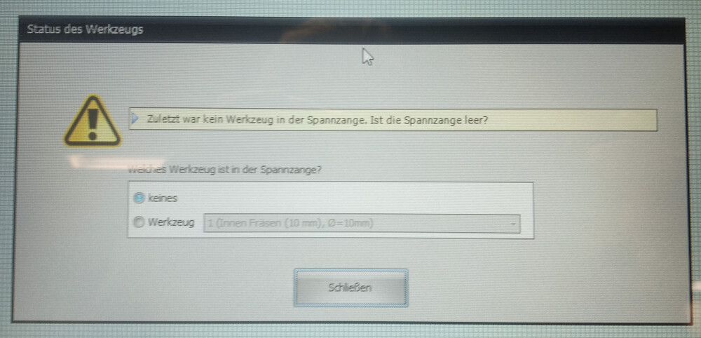
Open the NC-EAS(Y) Pro software. A prompt will appear asking if there is a milling tool installed in the cutter. Confirm to proceed.
Preparing the G-Code
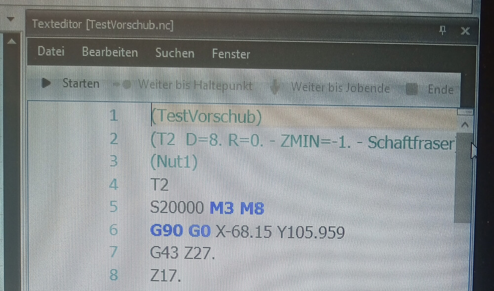
To enable the vacuum during the milling process, add an M8 command after the M3 command in the G-code. Once this modification is made, save the G-code file.
Performing a Reference Run
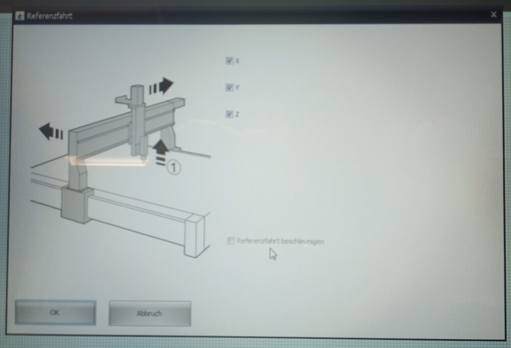
Before beginning the milling, perform a reference run to ensure correct positioning.
Adjusting the G-Code Position
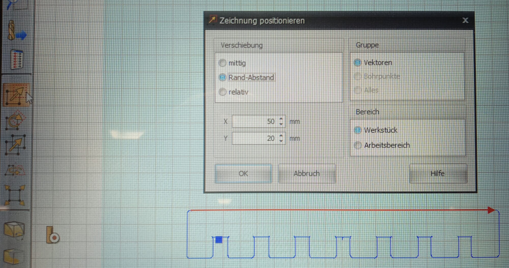
After loading the G-code, move it at least 10x10 mm from the lower-left corner. In my case, I shifted it further because there was a hole in that corner of the plate.
Estimating Milling Time
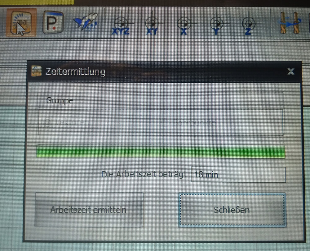
While you can estimate the milling time, please note that this calculation may not be completely accurate.
Starting the Milling Process
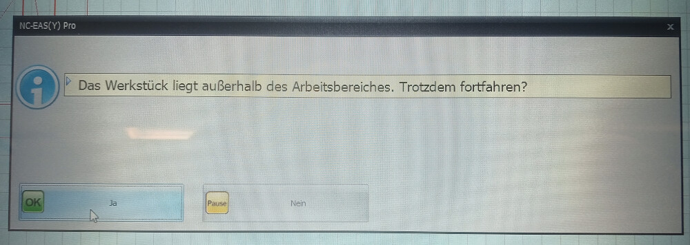
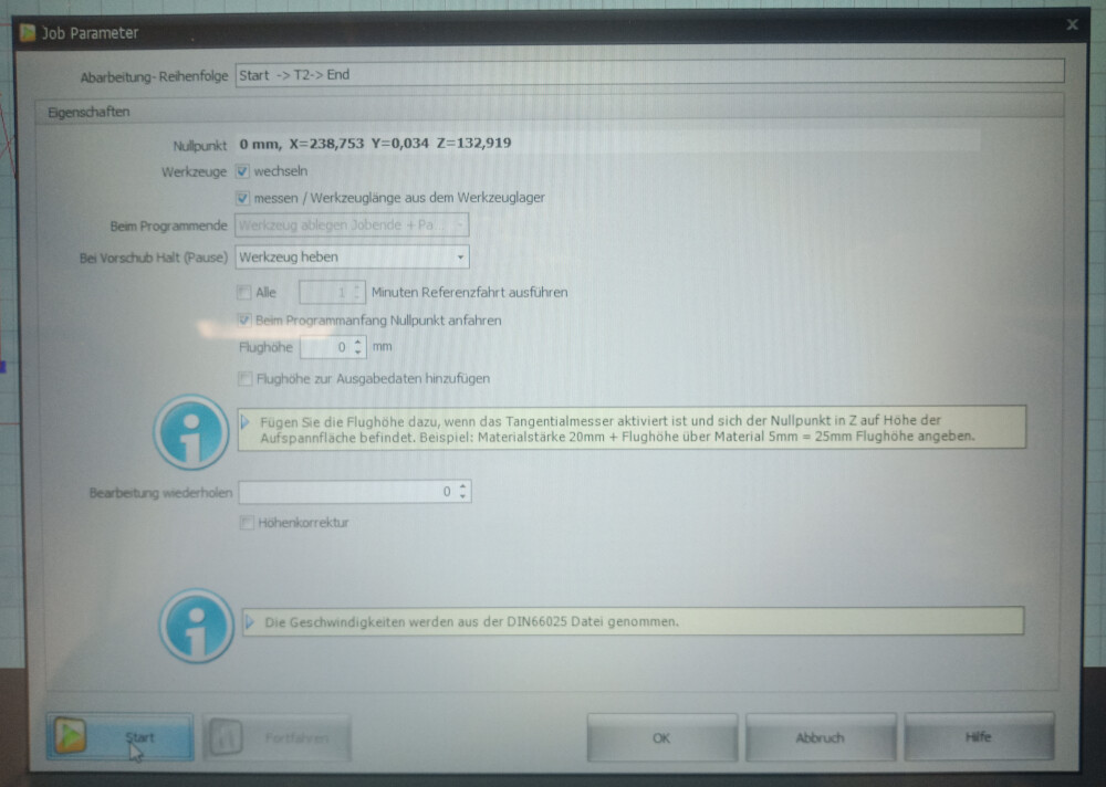
Upon starting the milling, you may see an error message indicating improper plate placement. This can be ignored—simply click "Yes" to continue. A settings window will then appear; no adjustments are needed here. Click the "Start" button to begin milling.
Using the Remote Control
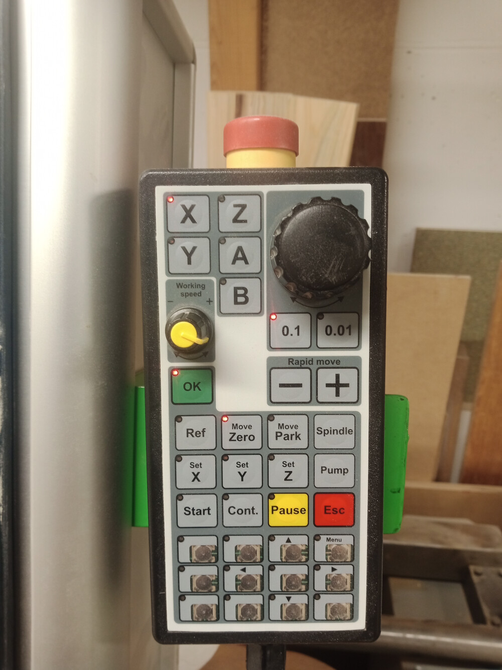
The remote control allows you to pause or stop the milling process if necessary.
Initial Z-Height Adjustment
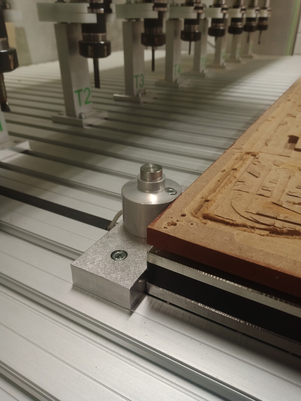
At the start of the process, the machine will automatically adjust to the correct Z-height for milling.
Joint Clearance Test
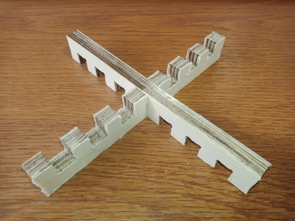
A joint clearance test was conducted using a 4 mm mill to reduce the size of dogbones on the inner contours of the joints. This process took around 30 minutes, with 2 mm steps in the Z-direction (half the mill diameter) to ensure precision. The joint at the center was 12 mm wide, with progressively larger and smaller widths on each side (12.72, 12.28, 12.24, 12.00, 11.76, 11.52, 11.28 mm).
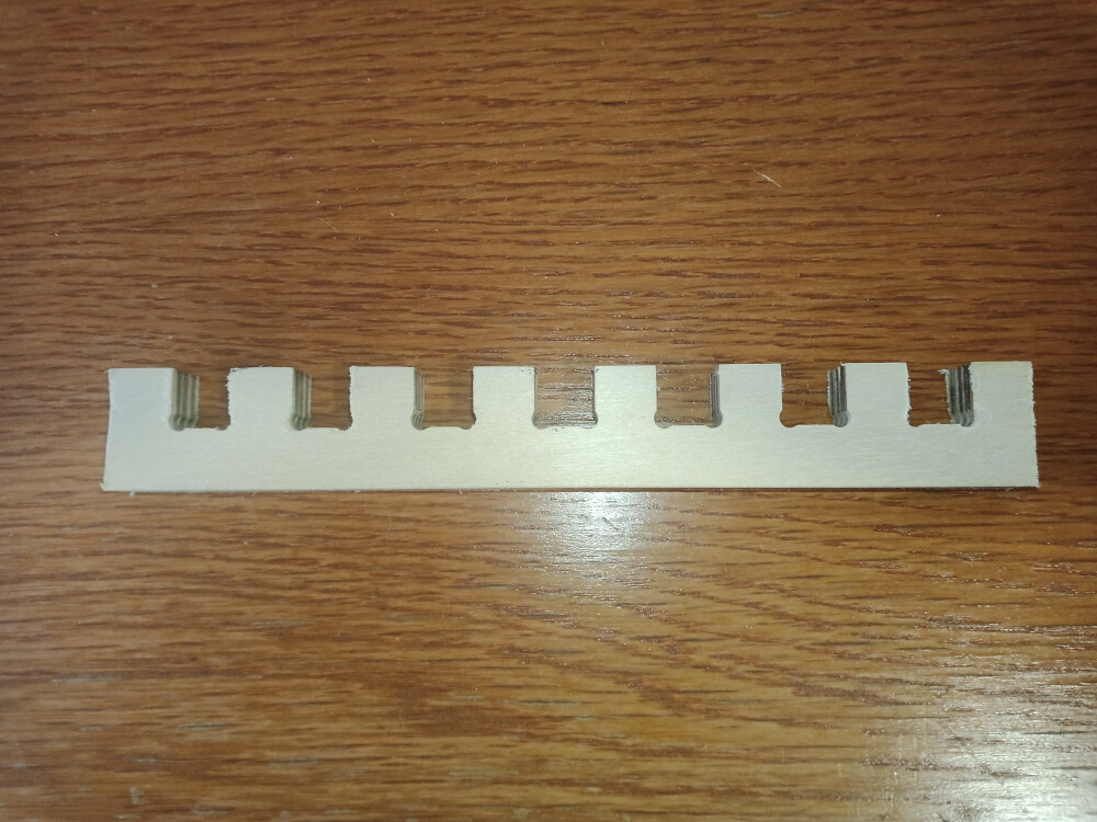
The central joints provided the best fit. However, since the plate thickness was 11.7 mm instead of 12 mm, joints should be made approximately 0.15 mm larger on each side for an optimal fit.
Video of the Cutting Process
Below is a video of the cutting process: