Computer controlled machining
Introduction
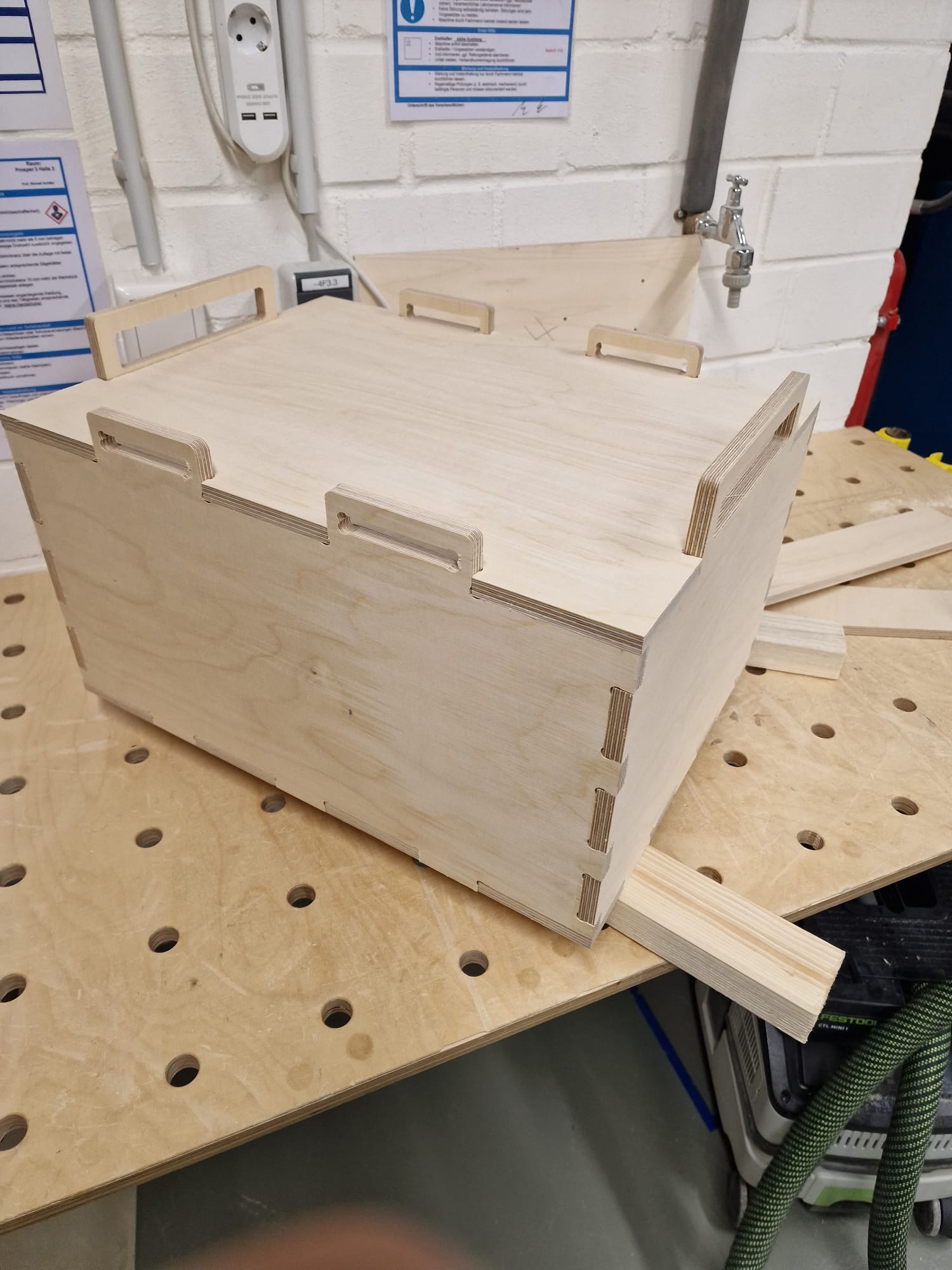
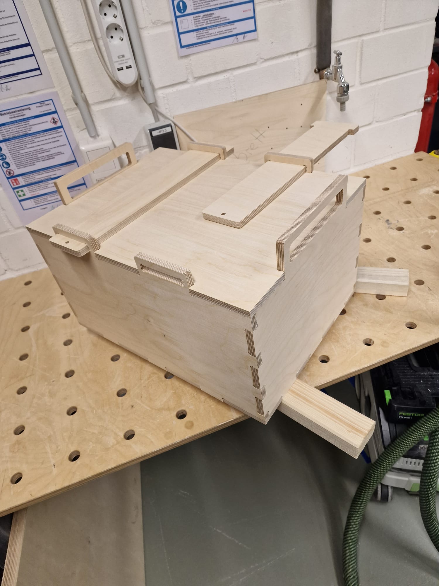
For my individual assignment, I decided to design and manufacture a large finger joint box using Fusion 360. The
box will be made out of wood and will measure around a meter in size. In addition, I plan to add two brackets on
the top of the box to hold the lid in place.
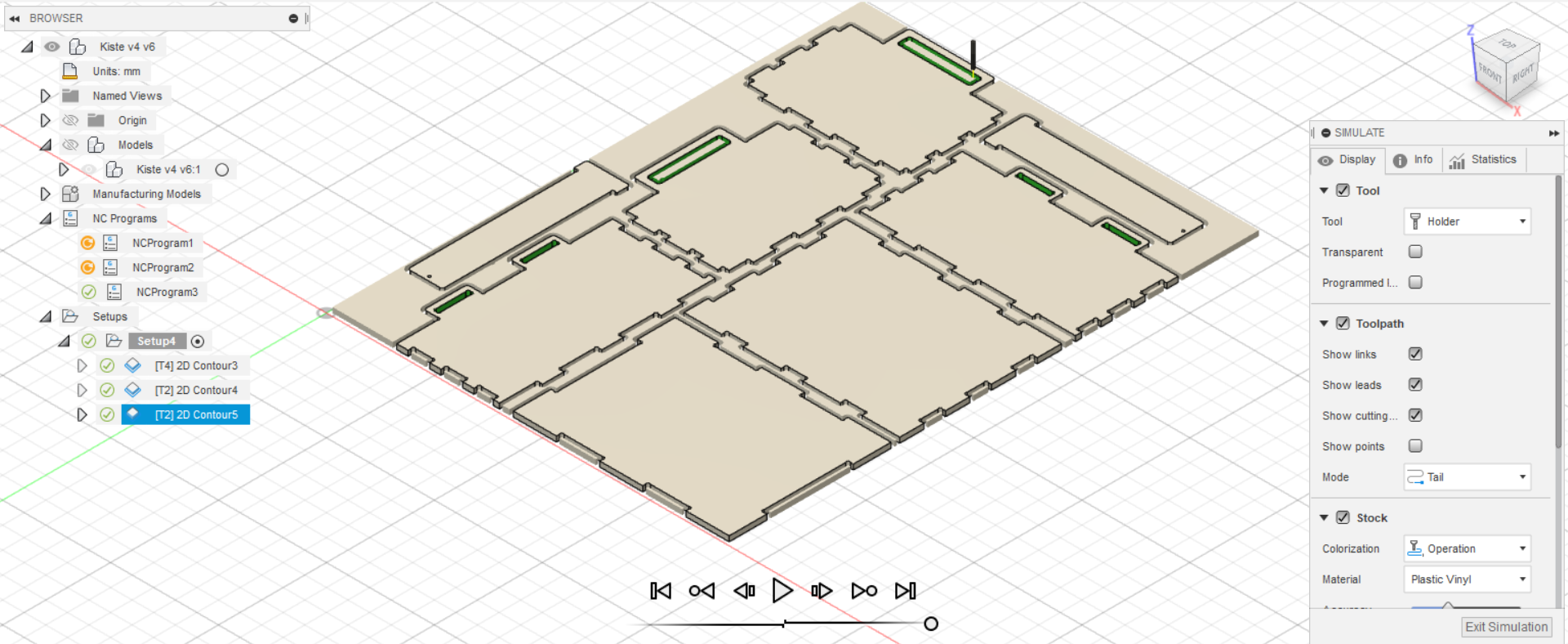
To manufacture this box, I plan to use a CNC machine to mill and cut the pieces precisely. This will ensure that
the joints fit perfectly and that the overall structure is strong and sturdy. With the help of Fusion 360, I will
be able to design the box and its components with accuracy and precision.
In the following sections, I will explain in detail the design process of the finger joint box and the brackets,
as well as the manufacturing process using a CNC machine.
Design
-
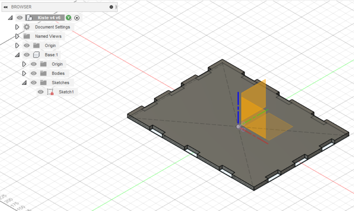
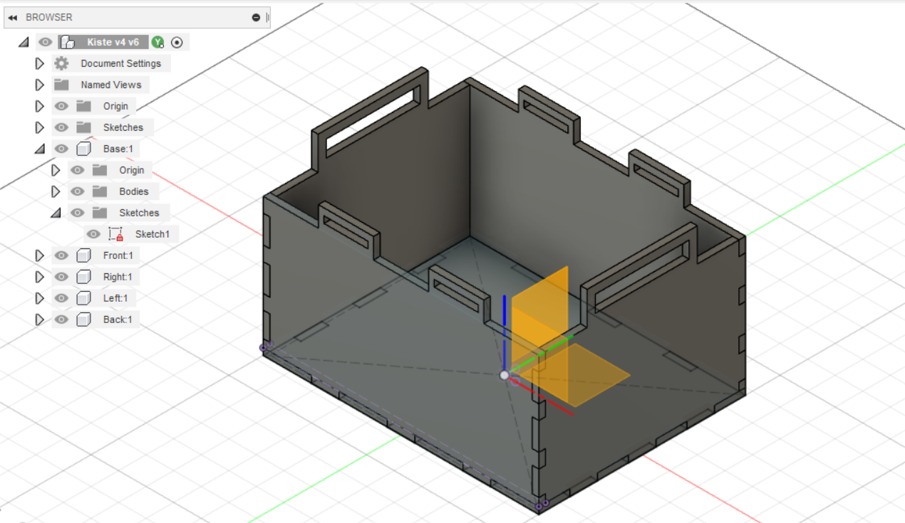
The first step in the design process was to create the bottom plate of the box using finger joints. I used
the joint tool in Fusion 360 to create the joints, ensuring that they fit together tightly to create a strong
structure.
-
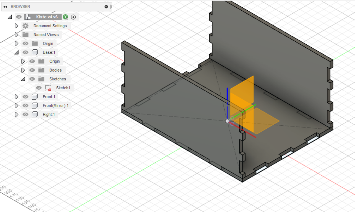
Next, I designed the front plate of the box and combined it with the bottom plate. To create the rear plate,
I mirrored the front plate using the mid-plane feature in Fusion 360.
-
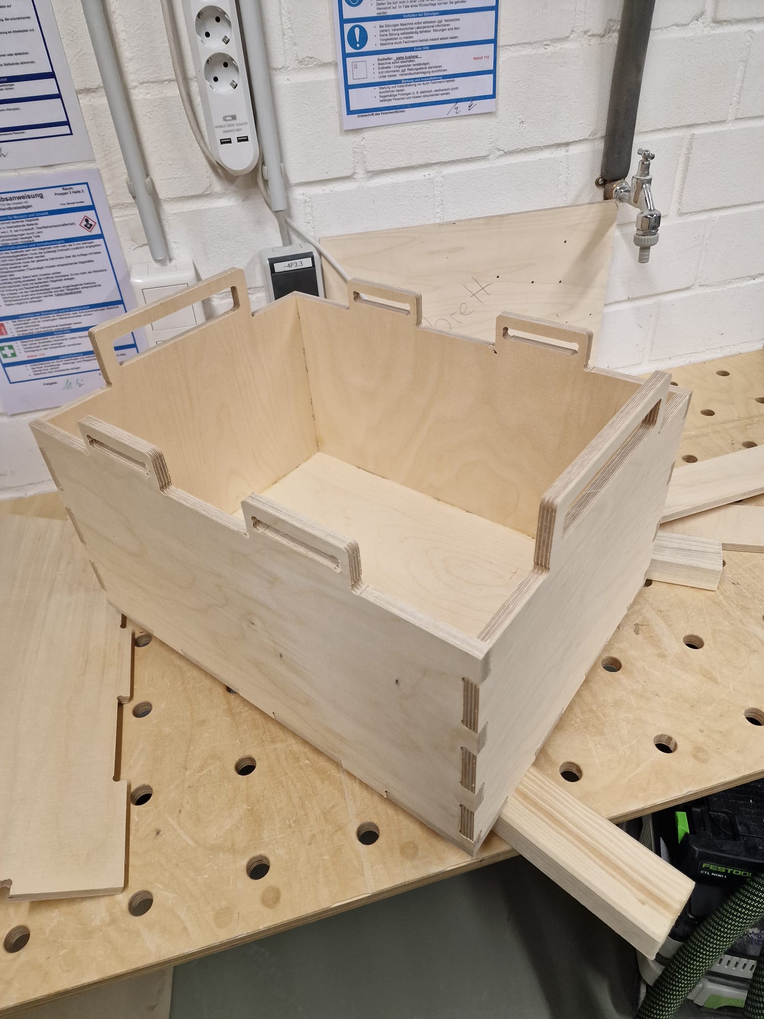
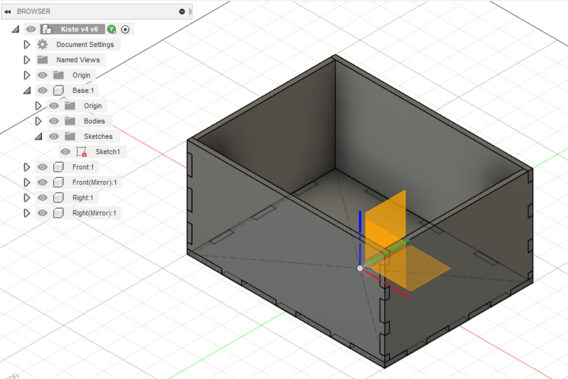
I repeated this process for the side plates, designing them with finger joints that fit into the joints on
the bottom and front plates. This created a sturdy and well-fitting box structure.
-
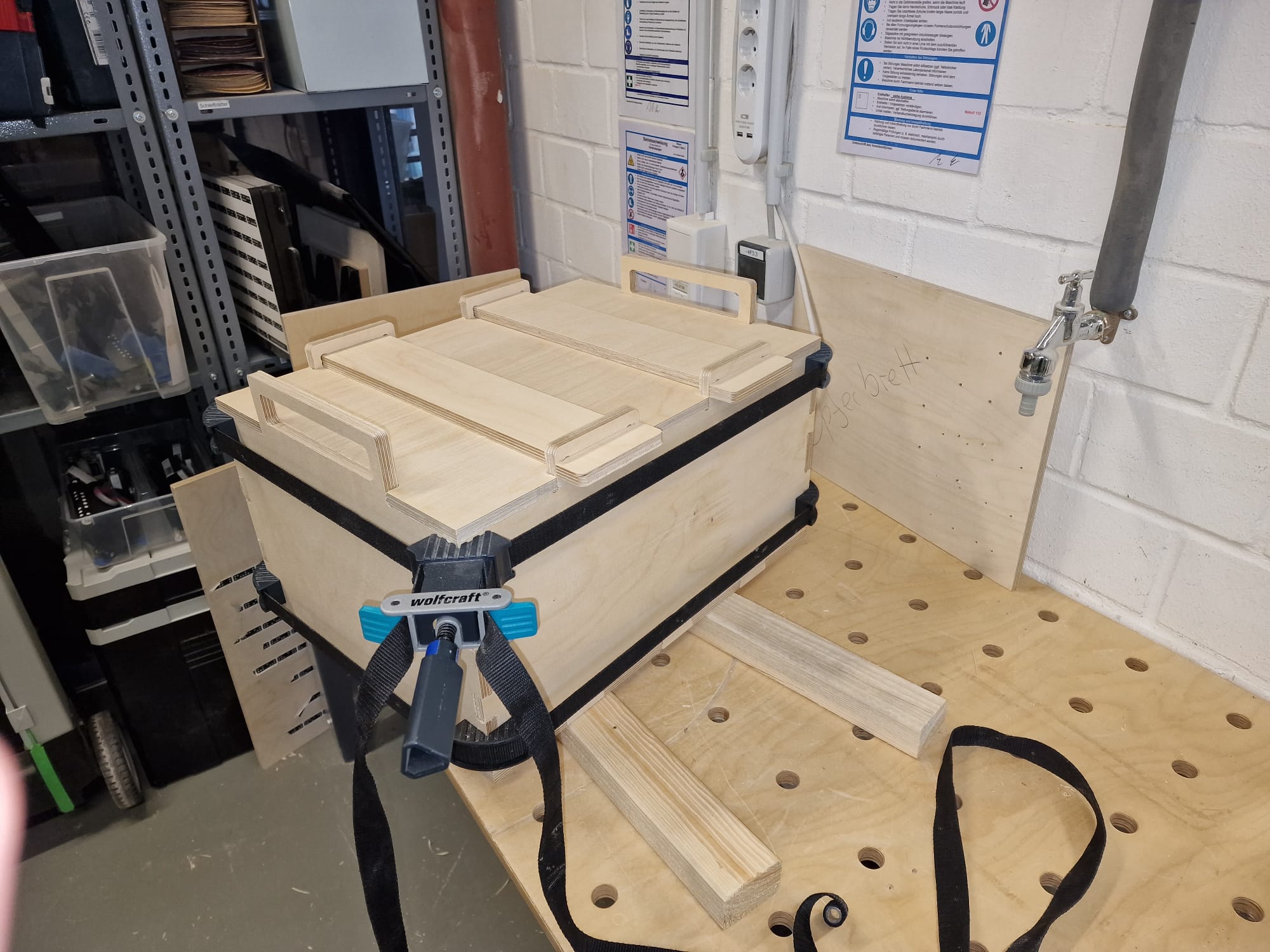
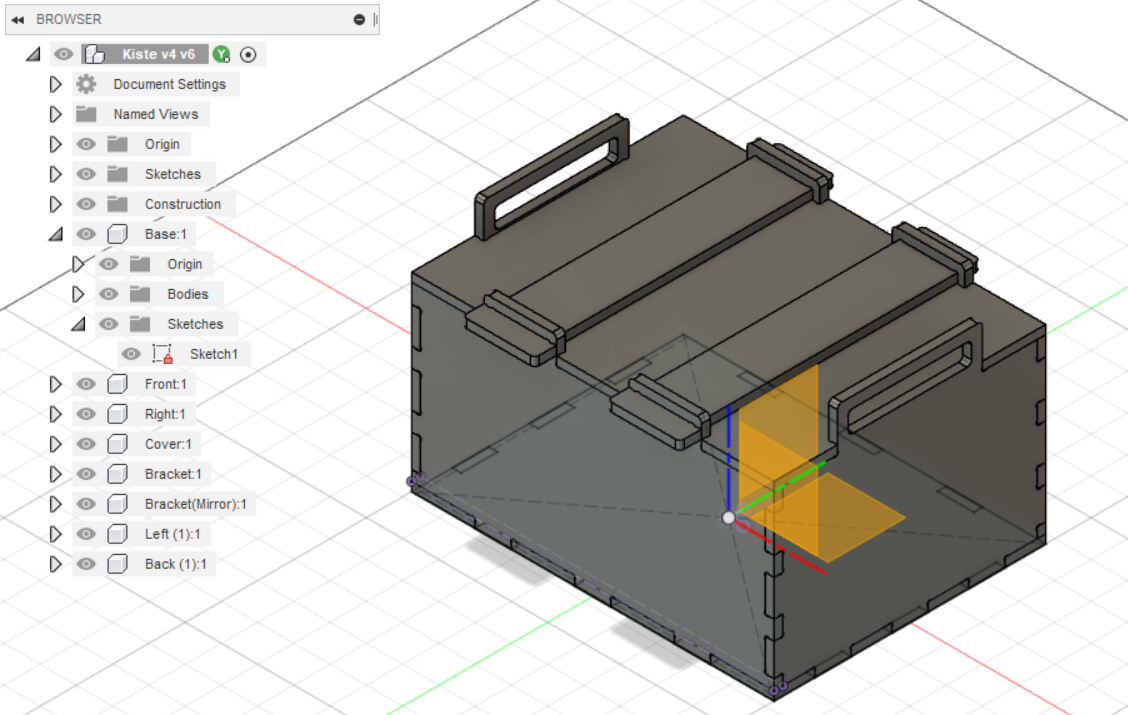
To hold the bottom plate of the box in place and prevent it from moving, I designed brackets on the pockets
that will attach to the top of the box. These pockets were precisely placed to fit the shape of the box and
provide a secure hold.
-
To ensure that the brackets stay in place, I added drill holes to the brackets. These holes allow for screws
to be inserted, securing the brackets in place and preventing them from moving.
Later i realised that finger-joints fit together, but to ensure that it has a strong structre i used glue. I
should also mention that I used the dogbones-forms.